User Manual
Page 3
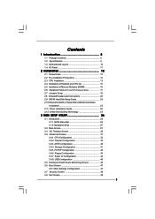
... Guide 24 2.10 Serial ATA (SATA) / Serial ATAII (SATAII) Hard Disks Installation 25 2.11 Driver Installation Guide 25 2.12 Untied Overclocking Technology 25 3 BIOS SETUP UTILITY 26 3.1 Introduction 26 3.1.1 BIOS Menu Bar 26 3.1.2 Navigation Keys 27 3.2 Main Screen 27 3.3 OC Tweaker Screen 28 3.4 Advanced Screen 31 3.4.1 CPU Configuration 32 3.4.2 Chipset Configuration 34...
... Guide 24 2.10 Serial ATA (SATA) / Serial ATAII (SATAII) Hard Disks Installation 25 2.11 Driver Installation Guide 25 2.12 Untied Overclocking Technology 25 3 BIOS SETUP UTILITY 26 3.1 Introduction 26 3.1.1 BIOS Menu Bar 26 3.1.2 Navigation Keys 27 3.2 Main Screen 27 3.3 OC Tweaker Screen 28 3.4 Advanced Screen 31 3.4.1 CPU Configuration 32 3.4.2 Chipset Configuration 34...
User Manual
Page 5
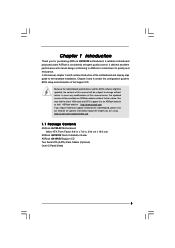
... control. Because the motherboard specifications and the BIOS software might be available on ASRock website as well. In case any modifications of the Support CD. www.asrock.com/support/index.asp 1.1 Package Contents ASRock G41M-S3 Motherboard (Micro ATX Form Factor: 9.6-in x 7.6-in, 24.4 cm x 19.3 cm) ASRock G41M-S3 Quick Installation Guide ASRock G41M-S3 Support CD Two Serial ATA (SATA...
... control. Because the motherboard specifications and the BIOS software might be available on ASRock website as well. In case any modifications of the Support CD. www.asrock.com/support/index.asp 1.1 Package Contents ASRock G41M-S3 Motherboard (Micro ATX Form Factor: 9.6-in x 7.6-in, 24.4 cm x 19.3 cm) ASRock G41M-S3 Quick Installation Guide ASRock G41M-S3 Support CD Two Serial ATA (SATA...
User Manual
Page 7
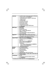
... is required) (see CAUTION 12) - AMI Legal BIOS - Supports "Plug and Play" - CPU, VCCM, NB, SB,VTT Voltage Multi-adjustment - Drivers, Utilities, AntiVirus Software (Trial Version), ASRock Software Suite (CyberLink DVD Suite and Creative Sound Blaster ... CPU Temperature Sensing Monitor - Intelligent Energy Saver (see CAUTION 13) - ASRock OC DNA (see CAUTION 11) - Connector - 4 x SATAII 3.0 Gb/s connectors (No Support for RAID and "Hot Plug" functions) (see CAUTION 9) BIOS Feature - 8Mb AMI BIOS - Front panel audio connector - 2 x USB 2.0 headers (support ...
... is required) (see CAUTION 12) - AMI Legal BIOS - Supports "Plug and Play" - CPU, VCCM, NB, SB,VTT Voltage Multi-adjustment - Drivers, Utilities, AntiVirus Software (Trial Version), ASRock Software Suite (CyberLink DVD Suite and Creative Sound Blaster ... CPU Temperature Sensing Monitor - Intelligent Energy Saver (see CAUTION 13) - ASRock OC DNA (see CAUTION 11) - Connector - 4 x SATAII 3.0 Gb/s connectors (No Support for RAID and "Hot Plug" functions) (see CAUTION 9) BIOS Feature - 8Mb AMI BIOS - Front panel audio connector - 2 x USB 2.0 headers (support ...

User Manual
Page 8
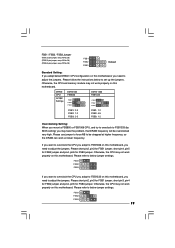
... at DDR3 533 if you adopt a DDR3 800 memory module. * If you adopt a DDR3 1333 memory module on this motherboard, it will operate in the BIOS, applying Untied Overclocking Technology, or using the thirdparty overclocking tools. This motherboard supports native FSB1333/1066/800 MHz. Please check the table below for the...
... at DDR3 533 if you adopt a DDR3 800 memory module. * If you adopt a DDR3 1333 memory module on this motherboard, it will operate in the BIOS, applying Untied Overclocking Technology, or using the thirdparty overclocking tools. This motherboard supports native FSB1333/1066/800 MHz. Please check the table below for the...
User Manual
Page 9
...savings. Your friends then can press key during the POST or press key to BIOS setup menu to EuP, the total AC power of the system or damage the CPU. 15. According to access ASRock Instant Flash. For EuP ready power supply selection, we recommend you what it back...your hardware devices to perform over-clocking. This convenient BIOS update tool allows you install the PC system. 16. Please visit our website for the operation procedures of ASRock OC Tuner. In other than 50% under 1.00W in Flash ROM. ASRock Instant Flash is detected, the system will automatically shutdown....
...savings. Your friends then can press key during the POST or press key to BIOS setup menu to EuP, the total AC power of the system or damage the CPU. 15. According to access ASRock Instant Flash. For EuP ready power supply selection, we recommend you what it back...your hardware devices to perform over-clocking. This convenient BIOS update tool allows you install the PC system. 16. Please visit our website for the operation procedures of ASRock OC Tuner. In other than 50% under 1.00W in Flash ROM. ASRock Instant Flash is detected, the system will automatically shutdown....
User Manual
Page 10
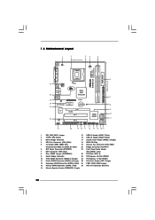
... Super IO AUDIO CODEC HD_AUDIO1 1 FLOPPY1 21 SATAII_3 RoHS PCIE2 PCI1 Intel ICH7 PCI2 CHA_FAN1 8Mb BIOS PLED PWRBTN 1 1 HDLED RESET PANEL 1 USB4_5 USB6_7 1 SPEAKER1 1 SATAII_1 20 19 18 17 16 15 14 13 12 G41M-S3 SATAII_2 SATAII_4 24.4cm (9.6 in) 6 7 8 9 10 11 1 PS2_USB_PWR1 Jumper 15 USB 2.0 Header (USB6_7, Blue) 2 775-Pin...
... Super IO AUDIO CODEC HD_AUDIO1 1 FLOPPY1 21 SATAII_3 RoHS PCIE2 PCI1 Intel ICH7 PCI2 CHA_FAN1 8Mb BIOS PLED PWRBTN 1 1 HDLED RESET PANEL 1 USB4_5 USB6_7 1 SPEAKER1 1 SATAII_1 20 19 18 17 16 15 14 13 12 G41M-S3 SATAII_2 SATAII_4 24.4cm (9.6 in) 6 7 8 9 10 11 1 PS2_USB_PWR1 Jumper 15 USB 2.0 Header (USB6_7, Blue) 2 775-Pin...

User Manual
Page 17
... motherboard. PCI slots: PCI slots are 2 PCI slots and 2 PCI Express slots on PCI Express VGA card to PCIE2 (PCIE x16 slot) and adjust the BIOS options "Primary Graphics Adapter" to [Onboard] and "Share Memory" to [Auto], then the onboard VGA will be enabled, and the primary screen will be onboard...
... motherboard. PCI slots: PCI slots are 2 PCI slots and 2 PCI Express slots on PCI Express VGA card to PCIE2 (PCIE x16 slot) and adjust the BIOS options "Primary Graphics Adapter" to [Onboard] and "Share Memory" to [Auto], then the onboard VGA will be enabled, and the primary screen will be onboard...
User Manual
Page 19
... FSB1333 on this motherboard, you need to adjust the jumpers. Please refer to adjust the jumpers. Please use jumper to force NB to FSB1333 (by BIOS setting) you may not work at lower frequency. DRAM CPU Jumper Settings DDR3 533 FSB533 FSB1 FSB2 FSB3 DDR3 1333 FSB1333 FSB1 FSB2 FSB3 FSB1...
... FSB1333 on this motherboard, you need to adjust the jumpers. Please refer to adjust the jumpers. Please use jumper to force NB to FSB1333 (by BIOS setting) you may not work at lower frequency. DRAM CPU Jumper Settings DDR3 533 FSB533 FSB1 FSB2 FSB3 DDR3 1333 FSB1333 FSB1 FSB2 FSB3 FSB1...
User Manual
Page 21
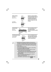
... connection and control of printer devices. Click the icon on the chassis must support HDA to [Enabled]. Connect Mic_IN (MIC) to install your system. 2. Enter BIOS Setup Utility. USB 2.0 Headers (9-pin USB6_7) (see p.10 No. 15) (9-pin USB4_5) (see p.10 No. 21) GND PRESENCE# MIC_RET OUT_RET 1 OUT2_L J_SENSE OUT2_R MIC2_R MIC2_L...
... connection and control of printer devices. Click the icon on the chassis must support HDA to [Enabled]. Connect Mic_IN (MIC) to install your system. 2. Enter BIOS Setup Utility. USB 2.0 Headers (9-pin USB6_7) (see p.10 No. 15) (9-pin USB4_5) (see p.10 No. 21) GND PRESENCE# MIC_RET OUT_RET 1 OUT2_L J_SENSE OUT2_R MIC2_R MIC2_L...
User Manual
Page 25
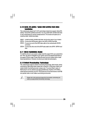
... data cable to install the SATA / SATAII hard disks. Then, the drivers compatible to the SATA / SATAII hard disk. STEP 4: Connect the other end of BIOS setup to set the selection from up to bottom side to your system, please insert the support CD to install those required drivers. You may...
... data cable to install the SATA / SATAII hard disks. Then, the drivers compatible to the SATA / SATAII hard disk. STEP 4: Connect the other end of BIOS setup to set the selection from up to bottom side to your system, please insert the support CD to install those required drivers. You may...
User Manual
Page 26
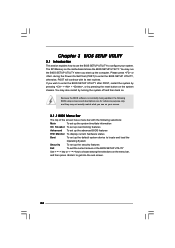
... by pressing + + , or by turning the system off and then back on the motherboard stores the BIOS SETUP UTILITY. If you start up the security features Exit To exit the current screen or the BIOS SETUP UTILITY Use < > key or < > key to choose among the selections on the menu bar,...screen. 26 The SPI Memory on . Please press or during the Power-On-Self-Test (POST) to enter the BIOS SETUP UTILITY, otherwise, POST will continue with the following BIOS setup screens and descriptions are for reference purpose only, and they may also restart by pressing the reset button on your...
... by pressing + + , or by turning the system off and then back on the motherboard stores the BIOS SETUP UTILITY. If you start up the security features Exit To exit the current screen or the BIOS SETUP UTILITY Use < > key or < > key to choose among the selections on the menu bar,...screen. 26 The SPI Memory on . Please press or during the Power-On-Self-Test (POST) to enter the BIOS SETUP UTILITY, otherwise, POST will continue with the following BIOS setup screens and descriptions are for reference purpose only, and they may also restart by pressing the reset button on your...
User Manual
Page 27
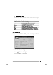
... Keys Please check the following table for all the settings To save changes and exit the BIOS SETUP UTILITY To jump to the Exit Screen or exit the current screen 3.2 Main Screen When you enter the BIOS SETUP UTILITY, the Main screen will appear and display the system overview... UTILITY Main OC Tweaker Advanced H/W Monitor Boot Security Exit System Overview System Time System Date [14:00:09] [Fri 10/16/2009] BIOS Version : G41M-S3 P1.00 Processor Type : Intel (R) Core (TM) 2 Duo CPU E6850 @ 3.00GHz (64bit) Processor Speed : 3148MHz Microcode Update : 6FB/B6 Cache Size : 1024KB...
... Keys Please check the following table for all the settings To save changes and exit the BIOS SETUP UTILITY To jump to the Exit Screen or exit the current screen 3.2 Main Screen When you enter the BIOS SETUP UTILITY, the Main screen will appear and display the system overview... UTILITY Main OC Tweaker Advanced H/W Monitor Boot Security Exit System Overview System Time System Date [14:00:09] [Fri 10/16/2009] BIOS Version : G41M-S3 P1.00 Processor Type : Intel (R) Core (TM) 2 Duo CPU E6850 @ 3.00GHz (64bit) Processor Speed : 3148MHz Microcode Update : 6FB/B6 Cache Size : 1024KB...
User Manual
Page 28
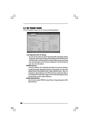
Please refer to Sub Screen F1 General Help F9 Load Defaults F10 Save and Exit ESC Exit v02.54 (C) Copyright 1985-2005, American Megatrends, Inc. BIOS SETUP UTILITY Main OC Tweaker Advanced H/W Monitor Boot Security Exit OC Tweaker Settings Load Optimized CPU OC Setting [Press Enter] DRAM Frequency DRAM Command Rate ...
Please refer to Sub Screen F1 General Help F9 Load Defaults F10 Save and Exit ESC Exit v02.54 (C) Copyright 1985-2005, American Megatrends, Inc. BIOS SETUP UTILITY Main OC Tweaker Advanced H/W Monitor Boot Security Exit OC Tweaker Settings Load Optimized CPU OC Setting [Press Enter] DRAM Frequency DRAM Command Rate ...
User Manual
Page 29
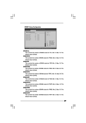
.... DRAM tRTP This controls the number of DRAM clocks for TRCD. DRAM tRRD This controls the number of DRAM clocks for TWTR. DRAM Timing Configuration BIOS SETUP UTILITY OC Tweaker DRAM Timing Control DRAM tCL 6 DRAM tRCD 6 DRAM tRP 6 DRAM tRAS 15 DRAM tRFC 44 DRAM tWR 6 DRAM tWTR 4 DRAM tRRD...
.... DRAM tRTP This controls the number of DRAM clocks for TRCD. DRAM tRRD This controls the number of DRAM clocks for TWTR. DRAM Timing Configuration BIOS SETUP UTILITY OC Tweaker DRAM Timing Control DRAM tCL 6 DRAM tRCD 6 DRAM tRP 6 DRAM tRAS 15 DRAM tRFC 44 DRAM tWR 6 DRAM tWTR 4 DRAM tRRD...
User Manual
Page 31
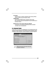
... this section may set the configurations for CPU CPU Configuration Chipset Configuration ACPI Configuration Storage Configuration PCIPnP Configuration Floppy Configuration SuperIO Configuration USB Configuration BIOS Update Utility ASRock Instant Flash Select Screen Select Item Enter Go to Sub Screen F1 General Help F9 Load Defaults F10 Save and Exit ESC Exit v02...
... this section may set the configurations for CPU CPU Configuration Chipset Configuration ACPI Configuration Storage Configuration PCIPnP Configuration Floppy Configuration SuperIO Configuration USB Configuration BIOS Update Utility ASRock Instant Flash Select Screen Select Item Enter Go to Sub Screen F1 General Help F9 Load Defaults F10 Save and Exit ESC Exit v02...

User Manual
Page 32
... or disable the feature of the system caches. 32 In the C1 power state, the processor maintains the context of Boot Failure Guard. 3.4.1 CPU Configuration BIOS SETUP UTILITY Advanced CPU Configuration Overclock Mode CPU Frequency (MHz) PCIE Frequency (MHz) Boot Failure Guard Spread Spectrum [Auto] [200] [100] [Enabled] [Auto] Ratio Status...
... or disable the feature of the system caches. 32 In the C1 power state, the processor maintains the context of Boot Failure Guard. 3.4.1 CPU Configuration BIOS SETUP UTILITY Advanced CPU Configuration Overclock Mode CPU Frequency (MHz) PCIE Frequency (MHz) Boot Failure Guard Spread Spectrum [Auto] [200] [100] [Enabled] [Auto] Ratio Status...

User Manual
Page 34
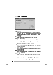
...The default value is [Auto]. DRAM CH0 G1 (Command) This controls the number of DRAM CH0 RCOMP ODT. 3.4.2 Chipset Configuration BIOS SETUP UTILITY Advanced Chipset Settings DRAM RCOMP and tRD Configuration DRAM DLL SKEW Configuration Fixed Mode Operation [Enabled] Intelligent Energy Saver Primary ...Control1) This controls the number of DRAM CH0 G0 (Data). Min: 1. The default value is [Auto]. DRAM RCOMP and tRD Configuration BIOS SETUP UTILITY Advanced DRAM RCOMP STRENGTH Settings DRAM CH0 RCOMP STRENGTH Info : 54-0-11-6-6-6-6 DRAM CH0 RCOMP ODT DRAM CH0 G0 (Data) ...
...The default value is [Auto]. DRAM CH0 G1 (Command) This controls the number of DRAM CH0 RCOMP ODT. 3.4.2 Chipset Configuration BIOS SETUP UTILITY Advanced Chipset Settings DRAM RCOMP and tRD Configuration DRAM DLL SKEW Configuration Fixed Mode Operation [Enabled] Intelligent Energy Saver Primary ...Control1) This controls the number of DRAM CH0 G0 (Data). Min: 1. The default value is [Auto]. DRAM RCOMP and tRD Configuration BIOS SETUP UTILITY Advanced DRAM RCOMP STRENGTH Settings DRAM CH0 RCOMP STRENGTH Info : 54-0-11-6-6-6-6 DRAM CH0 RCOMP ODT DRAM CH0 G0 (Data) ...

User Manual
Page 36
... CH1 CLKSET0 SKEW. DRAM CH0 CTRL0 SKEW This controls the number of DRAM CH0 CLKSET0 SKEW. The default value is [Auto]. DRAM DLL SKEW Configuration BIOS SETUP UTILITY Advanced DRAM DLL SKEW Settings DRAM CH0 CLKSET0 SKEW Info:0-0-0-0-0-0 DRAM CH0 CLKSET0 SKEW [Auto] DRAM CH0 CLKSET1 SKEW Info:0-0-0-0-0-0 DRAM CH0 CLKSET1...
... CH1 CLKSET0 SKEW. DRAM CH0 CTRL0 SKEW This controls the number of DRAM CH0 CLKSET0 SKEW. The default value is [Auto]. DRAM DLL SKEW Configuration BIOS SETUP UTILITY Advanced DRAM DLL SKEW Settings DRAM CH0 CLKSET0 SKEW Info:0-0-0-0-0-0 DRAM CH0 CLKSET0 SKEW [Auto] DRAM CH0 CLKSET1 SKEW Info:0-0-0-0-0-0 DRAM CH0 CLKSET1...
User Manual
Page 38
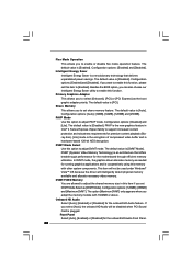
... family to adjust the shared memory size in this item to select [Onboard], [PCI] or [PCI Express] as the boot graphic adapter priority. Besides the BIOS option, you can also choose our Intelligent Energy Saver utility to enable or disable flex mode operation feature. Primary Graphics Adapter This allows you want...
... family to adjust the shared memory size in this item to select [Onboard], [PCI] or [PCI Express] as the boot graphic adapter priority. Besides the BIOS option, you can also choose our Intelligent Energy Saver utility to enable or disable flex mode operation feature. Primary Graphics Adapter This allows you want...
User Manual
Page 40
... option to [Enabled] if you plan to use this item to enable or disable RTC (Real Time Clock) to power on the system. 3.4.3 ACPI Configuration BIOS SETUP UTILITY Advanced ACPI Configuration Suspend To RAM Restore on AC/Power Loss This allows you to set the power state after an unexpected AC...
... option to [Enabled] if you plan to use this item to enable or disable RTC (Real Time Clock) to power on the system. 3.4.3 ACPI Configuration BIOS SETUP UTILITY Advanced ACPI Configuration Suspend To RAM Restore on AC/Power Loss This allows you to set the power state after an unexpected AC...


