
User Manual
Page 3
... Guide 24 2.10 Serial ATA (SATA) / Serial ATAII (SATAII) Hard Disks Installation 25 2.11 Driver Installation Guide 25 2.12 Untied Overclocking Technology 25 3 BIOS SETUP UTILITY 26 3.1 Introduction 26 3.1.1 BIOS Menu Bar 26 3.1.2 Navigation Keys 27 3.2 Main Screen 27 3.3 OC Tweaker Screen 28 3.4 Advanced Screen 32 3.4.1 CPU Configuration 33 3.4.2 Chipset Configuration 35...
... Guide 24 2.10 Serial ATA (SATA) / Serial ATAII (SATAII) Hard Disks Installation 25 2.11 Driver Installation Guide 25 2.12 Untied Overclocking Technology 25 3 BIOS SETUP UTILITY 26 3.1 Introduction 26 3.1.1 BIOS Menu Bar 26 3.1.2 Navigation Keys 27 3.2 Main Screen 27 3.3 OC Tweaker Screen 28 3.4 Advanced Screen 32 3.4.1 CPU Configuration 33 3.4.2 Chipset Configuration 35...
User Manual
Page 5
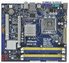
... will be subject to change without further notice. www.asrock.com/support/index.asp 1.1 Package Contents ASRock G41C-VS Motherboard (Micro ATX Form Factor: 8.8-in x 7.8-in, 22.4 cm x 19.8 cm) ASRock G41C-VS Quick Installation Guide ASRock G41C-VS Support CD Two Serial ATA (SATA) Data Cables (...ASRock website as well. ASRock website http://www.asrock.com If you for specific information about the model you are using. Because the motherboard specifications and the BIOS software might be updated, the content of this motherboard, please visit our website for purchasing ASRock G41C-VS...
... will be subject to change without further notice. www.asrock.com/support/index.asp 1.1 Package Contents ASRock G41C-VS Motherboard (Micro ATX Form Factor: 8.8-in x 7.8-in, 22.4 cm x 19.8 cm) ASRock G41C-VS Quick Installation Guide ASRock G41C-VS Support CD Two Serial ATA (SATA) Data Cables (...ASRock website as well. ASRock website http://www.asrock.com If you for specific information about the model you are using. Because the motherboard specifications and the BIOS software might be updated, the content of this motherboard, please visit our website for purchasing ASRock G41C-VS...
User Manual
Page 7
..., Vcore - Front panel audio connector - 2 x USB 2.0 headers (support 4 USB 2.0 ports) (see CAUTION 9) - VCCM, NB, VTT, GTLRef Voltage Multi-adjustment - ASRock OC Tuner (see CAUTION 8) - 8Mb AMI BIOS - ASRock Instant Flash (see CAUTION 14) - ASRock U-COP (see CAUTION 11) - EuP Ready (EuP ready power supply is required) (see CAUTION 10) - CPU/Chassis FAN connector - 24...
..., Vcore - Front panel audio connector - 2 x USB 2.0 headers (support 4 USB 2.0 ports) (see CAUTION 9) - VCCM, NB, VTT, GTLRef Voltage Multi-adjustment - ASRock OC Tuner (see CAUTION 8) - 8Mb AMI BIOS - ASRock Instant Flash (see CAUTION 14) - ASRock U-COP (see CAUTION 11) - EuP Ready (EuP ready power supply is required) (see CAUTION 10) - CPU/Chassis FAN connector - 24...

User Manual
Page 8
...DDR2 667, DDR2 800 800 DDR3 800 DDR2 667, DDR2 800 533 DDR3 800 DDR2 533 * DDR3 1333 memory modules will operate in the BIOS, applying Untied Overclocking Technology, or using the thirdparty overclocking tools. For Windows® OS with 64-bit CPU, there is a certain risk ...operating system limitation, the actual memory size may affect your own risk and expense. * For detailed product information, please visit our website: http://www.asrock.com WARNING Please realize that there is no such limitation. 6. Overclocking may be done at DDR3 533 if you adopt a DDR3 800 memory module....
...DDR2 667, DDR2 800 800 DDR3 800 DDR2 667, DDR2 800 533 DDR3 800 DDR2 533 * DDR3 1333 memory modules will operate in the BIOS, applying Untied Overclocking Technology, or using the thirdparty overclocking tools. For Windows® OS with 64-bit CPU, there is a certain risk ...operating system limitation, the actual memory size may affect your own risk and expense. * For detailed product information, please visit our website: http://www.asrock.com WARNING Please realize that there is no such limitation. 6. Overclocking may be done at DDR3 533 if you adopt a DDR3 800 memory module....

User Manual
Page 9
Please visit our website for the operation procedures of ASRock OC Tuner. ASRock website: http://www.asrock.com 11. The software name itself - It helps you to save the new BIOS file to your BIOS only in a few clicks without preparing an additional floppy diskette or other complicated flash utility. To improve ...be noted that the OC profile can load the OC profile to their own system to access ASRock Instant Flash. Before you can press key during the POST or press key to BIOS setup menu to get the best system performance under 1.00W in Flash ROM. According to perform...
Please visit our website for the operation procedures of ASRock OC Tuner. ASRock website: http://www.asrock.com 11. The software name itself - It helps you to save the new BIOS file to your BIOS only in a few clicks without preparing an additional floppy diskette or other complicated flash utility. To improve ...be noted that the OC profile can load the OC profile to their own system to access ASRock Instant Flash. Before you can press key during the POST or press key to BIOS setup menu to get the best system performance under 1.00W in Flash ROM. According to perform...
User Manual
Page 10
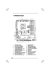
Blue) 19 BIOS SPI Chip 7 PCI Express x16 Slot (PCIE1) 20 FSB1 Jumper 8 South Bridge Controller 21 EUP Audio Jumper (EUP_AUDIO1) 9 Secondary SATAII Connector (SATAII_2; Red) 23 Front ...: RJ-45 Super IO HD_AUDIO1 1 LAN PHY EUP_LAN 1 1 EUP_AUDIO1 AUDIO CODEC 8Mb BIOS FSB1 1 CMOS Battery LPT1 Intel G41 Chipset PCIE1 RoHS CHA_FAN1 CLRCMOS1 USB6_7 1 USB4_5 1 PCI1 SPEAKER1 1 PANEL 1 PLED PWRBTN 1 HDLED RESET 17 16 15 14 13 12 DX10 G41C-VS Intel ICH7 IDE1 11 SATAII_2 SATAII_1 7 8 9 10 1 PS2_USB_PWR1 Jumper 13 Chassis...
Blue) 19 BIOS SPI Chip 7 PCI Express x16 Slot (PCIE1) 20 FSB1 Jumper 8 South Bridge Controller 21 EUP Audio Jumper (EUP_AUDIO1) 9 Secondary SATAII Connector (SATAII_2; Red) 23 Front ...: RJ-45 Super IO HD_AUDIO1 1 LAN PHY EUP_LAN 1 1 EUP_AUDIO1 AUDIO CODEC 8Mb BIOS FSB1 1 CMOS Battery LPT1 Intel G41 Chipset PCIE1 RoHS CHA_FAN1 CLRCMOS1 USB6_7 1 USB4_5 1 PCI1 SPEAKER1 1 PANEL 1 PLED PWRBTN 1 HDLED RESET 17 16 15 14 13 12 DX10 G41C-VS Intel ICH7 IDE1 11 SATAII_2 SATAII_1 7 8 9 10 1 PS2_USB_PWR1 Jumper 13 Chassis...

User Manual
Page 18
... and PCI Express Slots) There are 1 PCI slot and 1 PCI Express slot on PCI Express VGA card to PCIE1 (PCIE x16 slot) and adjust the BIOS options "Primary Graphics Adapter" to [Onboard] and "Share Memory" to [Auto], then the onboard VGA will be enabled, and the primary screen will be onboard...
... and PCI Express Slots) There are 1 PCI slot and 1 PCI Express slot on PCI Express VGA card to PCIE1 (PCIE x16 slot) and adjust the BIOS options "Primary Graphics Adapter" to [Onboard] and "Share Memory" to [Auto], then the onboard VGA will be enabled, and the primary screen will be onboard...
User Manual
Page 21
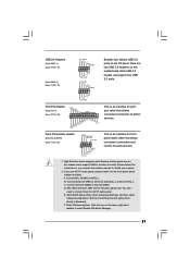
... for AC'97 audio panel. Each USB 2.0 header can support two USB 2.0 ports. You don't need to connect them for HD audio panel only. Enter BIOS Setup Utility. Enter Advanced Settings, and then select Chipset Configuration.
... for AC'97 audio panel. Each USB 2.0 header can support two USB 2.0 ports. You don't need to connect them for HD audio panel only. Enter BIOS Setup Utility. Enter Advanced Settings, and then select Chipset Configuration.

User Manual
Page 25
... to the SATA / SATAII hard disk. 2.11 Driver Installation Guide To install the drivers to your optical drive first. STEP 4: Connect the other end of BIOS setup to set the selection from up to bottom side to your system, please insert the support CD to install those required drivers. Please follow...
... to the SATA / SATAII hard disk. 2.11 Driver Installation Guide To install the drivers to your optical drive first. STEP 4: Connect the other end of BIOS setup to set the selection from up to bottom side to your system, please insert the support CD to install those required drivers. Please follow...
User Manual
Page 26
... screens and descriptions are for reference purpose only, and they may not exactly match what you see on the motherboard stores the BIOS SETUP UTILITY. Because the BIOS software is constantly being updated, the following selections: Main To set up the system time/date information OC Tweaker To set up ... < > key or < > key to choose among the selections on the system chassis. The SPI Memory on your system. If you wish to enter the BIOS SETUP UTILITY after POST, restart the system by pressing + + , or by turning the system off and then back on. Please press or during the Power...
... screens and descriptions are for reference purpose only, and they may not exactly match what you see on the motherboard stores the BIOS SETUP UTILITY. Because the BIOS software is constantly being updated, the following selections: Main To set up the system time/date information OC Tweaker To set up ... < > key or < > key to choose among the selections on the system chassis. The SPI Memory on your system. If you wish to enter the BIOS SETUP UTILITY after POST, restart the system by pressing + + , or by turning the system off and then back on. Please press or during the Power...

User Manual
Page 27
... To bring up the selected screen To display the General Help Screen To load optimal default values for the function description of each navigation key. BIOS Version : G41C-VS P1.00 Processor Type : Intel (R) Core (TM) 2 Duo CPU E6850 @ 3.00GHz (64bit) Processor Speed : 3148MHz Microcode Update : 6FB/B6 ...To jump to the Exit Screen or exit the current screen 3.2 Main Screen When you enter the BIOS SETUP UTILITY, the Main screen will appear and display the system overview BIOS SETUP UTILITY Main OC Tweaker Advanced H/W Monitor Boot Security Exit System Overview System Time System Date [...
... To bring up the selected screen To display the General Help Screen To load optimal default values for the function description of each navigation key. BIOS Version : G41C-VS P1.00 Processor Type : Intel (R) Core (TM) 2 Duo CPU E6850 @ 3.00GHz (64bit) Processor Speed : 3148MHz Microcode Update : 6FB/B6 ...To jump to the Exit Screen or exit the current screen 3.2 Main Screen When you enter the BIOS SETUP UTILITY, the Main screen will appear and display the system overview BIOS SETUP UTILITY Main OC Tweaker Advanced H/W Monitor Boot Security Exit System Overview System Time System Date [...
User Manual
Page 28
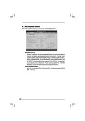
... DDR3_1066] or [667MHz DDR3_1333] for DDR3 or [266MHz DDR2_533], [333MHz DDR2_667] or [400MHz DDR2_800] for the CPU FSB frequency and its corresponding memory support frequency. BIOS SETUP UTILITY Main OC Tweaker Advanced H/W Monitor Boot Security Exit OC Tweaker Settings DRAM Frequency DRAM Command Rate DRAM Timing Configuration [Auto] [Auto] If you...
... DDR3_1066] or [667MHz DDR3_1333] for DDR3 or [266MHz DDR2_533], [333MHz DDR2_667] or [400MHz DDR2_800] for the CPU FSB frequency and its corresponding memory support frequency. BIOS SETUP UTILITY Main OC Tweaker Advanced H/W Monitor Boot Security Exit OC Tweaker Settings DRAM Frequency DRAM Command Rate DRAM Timing Configuration [Auto] [Auto] If you...

User Manual
Page 29
.... DRAM tRRD This controls the number of DRAM clocks for TRP. DRAM tWTR This controls the number of DRAM clocks for TRFC. DRAM Timing Configuration BIOS SETUP UTILITY OC Tweaker DRAM Timing Control DRAM tCL 6 DRAM tRCD 6 DRAM tRP 6 DRAM tRAS 15 DRAM tRFC 44 DRAM tWR 6 DRAM tWTR 4 DRAM tRRD...
.... DRAM tRRD This controls the number of DRAM clocks for TRP. DRAM tWTR This controls the number of DRAM clocks for TRFC. DRAM Timing Configuration BIOS SETUP UTILITY OC Tweaker DRAM Timing Control DRAM tCL 6 DRAM tRCD 6 DRAM tRP 6 DRAM tRAS 15 DRAM tRFC 44 DRAM tWR 6 DRAM tWTR 4 DRAM tRRD...

User Manual
Page 32
CPU Configuration Chipset Configuration ACPI Configuration Storage Configuration PCIPnP Configuration SuperIO Configuration USB Configuration BIOS Update Utility ASRock Instant Flash Select Screen Select Item Enter Go to malfunction. 32 BIOS SETUP UTILITY Main OC Tweaker Advanced H/W Monitor Boot Security Exit Advanced Settings Options for the following items: CPU Configuration, Chipset Configuration, ACPI Configuration, Storage...
CPU Configuration Chipset Configuration ACPI Configuration Storage Configuration PCIPnP Configuration SuperIO Configuration USB Configuration BIOS Update Utility ASRock Instant Flash Select Screen Select Item Enter Go to malfunction. 32 BIOS SETUP UTILITY Main OC Tweaker Advanced H/W Monitor Boot Security Exit Advanced Settings Options for the following items: CPU Configuration, Chipset Configuration, ACPI Configuration, Storage...

User Manual
Page 33
... CPU frequency. If the CPU you adopt supports EIST (Intel (R) SpeedStep(tm) tech.), and you plan to allow you will find this motherboard. 3.4.1 CPU Configuration BIOS SETUP UTILITY Advanced CPU Configuration Overclock Mode CPU Frequency (MHz) PCIE Frequency (MHz) Boot Failure Guard Spread Spectrum [Auto] [200] [100] [Enabled] [Auto] Ratio Status...
... CPU frequency. If the CPU you adopt supports EIST (Intel (R) SpeedStep(tm) tech.), and you plan to allow you will find this motherboard. 3.4.1 CPU Configuration BIOS SETUP UTILITY Advanced CPU Configuration Overclock Mode CPU Frequency (MHz) PCIE Frequency (MHz) Boot Failure Guard Spread Spectrum [Auto] [200] [100] [Enabled] [Auto] Ratio Status...

User Manual
Page 35
Min: 1. Min: 1. 3.4.2 Chipset Configuration BIOS SETUP UTILITY Advanced Chipset Settings DRAM RCOMP and tRD Configuration DRAM DLL SKEW Configuration Fixed Mode Operation [Enabled] Intelligent Energy Saver Primary Graphics Adapter Shared ... DRAM CH0 G1 (Command). DRAM CH0 G1 (Command) This controls the number of DRAM CH0 G0 (Data). Max: 15. Min: 1. DRAM RCOMP and tRD Configuration BIOS SETUP UTILITY Advanced DRAM RCOMP STRENGTH Settings DRAM CH0 RCOMP Settings : 54-0-11-6-6-6-6 DRAM CH0 RCOMP ODT DRAM CH0 G0 (Data) [Auto] [Auto] DRAM CH0...
Min: 1. Min: 1. 3.4.2 Chipset Configuration BIOS SETUP UTILITY Advanced Chipset Settings DRAM RCOMP and tRD Configuration DRAM DLL SKEW Configuration Fixed Mode Operation [Enabled] Intelligent Energy Saver Primary Graphics Adapter Shared ... DRAM CH0 G1 (Command). DRAM CH0 G1 (Command) This controls the number of DRAM CH0 G0 (Data). Max: 15. Min: 1. DRAM RCOMP and tRD Configuration BIOS SETUP UTILITY Advanced DRAM RCOMP STRENGTH Settings DRAM CH0 RCOMP Settings : 54-0-11-6-6-6-6 DRAM CH0 RCOMP ODT DRAM CH0 G0 (Data) [Auto] [Auto] DRAM CH0...

User Manual
Page 37
... CH1 CLKSET1 SKEW. The default value is [Auto]. DRAM CH0 CTRL3 SKEW This controls the number of DRAM CH0 CTRL3 SKEW. DRAM DLL SKEW Configuration BIOS SETUP UTILITY Advanced DRAM DLL SKEW Settings DRAM CH0 CLKSET0 SKEW Info:0-0-0-0-0-0 DRAM CH0 CLKSET0 SKEW [Auto] DRAM CH0 CLKSET1 SKEW Info:0-0-0-0-0-0 DRAM CH0 CLKSET1...
... CH1 CLKSET1 SKEW. The default value is [Auto]. DRAM CH0 CTRL3 SKEW This controls the number of DRAM CH0 CTRL3 SKEW. DRAM DLL SKEW Configuration BIOS SETUP UTILITY Advanced DRAM DLL SKEW Settings DRAM CH0 CLKSET0 SKEW Info:0-0-0-0-0-0 DRAM CH0 CLKSET0 SKEW [Auto] DRAM CH0 CLKSET1 SKEW Info:0-0-0-0-0-0 DRAM CH0 CLKSET1...

User Manual
Page 39
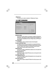
... adapter priority. Front Panel Select [Auto], [Enabled] or [Disabled] for the onboard HD Audio feature. Configuration options: [Auto], [32MB], [64MB], [128MB] and [256MB]. Besides the BIOS option, you to select [Onboard], [PCI] or [PCI Express] as [DVMT Mode]. DVMT (Dynamic Video Memory Technology) is [PCI]. Onboard HD Audio Select [Auto], [Enabled...
... adapter priority. Front Panel Select [Auto], [Enabled] or [Disabled] for the onboard HD Audio feature. Configuration options: [Auto], [32MB], [64MB], [128MB] and [256MB]. Besides the BIOS option, you to select [Onboard], [PCI] or [PCI Express] as [DVMT Mode]. DVMT (Dynamic Video Memory Technology) is [PCI]. Onboard HD Audio Select [Auto], [Enabled...
User Manual
Page 40
OnBoard Lan This allows you to enable or disable the "OnBoard Lan" feature. 3.4.3 ACPI Configuration BIOS SETUP UTILITY Advanced ACPI Configuration Suspend To RAM Restore on the system from the power-soft-off when the power recovers. If you to set ...
OnBoard Lan This allows you to enable or disable the "OnBoard Lan" feature. 3.4.3 ACPI Configuration BIOS SETUP UTILITY Advanced ACPI Configuration Suspend To RAM Restore on the system from the power-soft-off when the power recovers. If you to set ...

User Manual
Page 41
... will use this motherboard to enable or disable ACPI HPET Table. ACPI HPET Table Use this item to submit Windows® VistaTM certification. 3.4.4 Storage Configuration BIOS SETUP UTILITY Advanced Storage Configuration ATA/IDE Configuration SATAII_1 SATAII_2 IDE1 Master IDE1 Slave [Enhanced] [Hard Disk] [Not Detected] [Not Detected] [Not Detected] Set [Compatible...
... will use this motherboard to enable or disable ACPI HPET Table. ACPI HPET Table Use this item to submit Windows® VistaTM certification. 3.4.4 Storage Configuration BIOS SETUP UTILITY Advanced Storage Configuration ATA/IDE Configuration SATAII_1 SATAII_2 IDE1 Master IDE1 Slave [Enhanced] [Hard Disk] [Not Detected] [Not Detected] [Not Detected] Set [Compatible...


