User Manual
Page 3
Contents 1 Introduction 5 1.1 Package Contents 5 1.2 Specifications 6 1.3 Motherboard Layout (G41C-GS / G41C-S 11 1.4 I/O Panel (G41C-GS 12 1.5 I/O Panel (G41C-S 13 2 Installation 14 2.1 Screw Holes 14 2.2 Pre-installation Precautions 14 2.3 CPU Installation 15 2.4 Installation of...SATA) / Serial ATAII (SATAII) Hard Disks Installation 26 2.11 Driver Installation Guide 26 2.12 Untied Overclocking Technology 26 3 BIOS SETUP UTILITY 27 3.1 Introduction 27 3.1.1 BIOS Menu Bar 27 3.1.2 Navigation Keys 28 3.2 Main Screen 28 3.3 OC Tweaker Screen 30 3.4 Advanced Screen 34 3.4.1 CPU ...
Contents 1 Introduction 5 1.1 Package Contents 5 1.2 Specifications 6 1.3 Motherboard Layout (G41C-GS / G41C-S 11 1.4 I/O Panel (G41C-GS 12 1.5 I/O Panel (G41C-S 13 2 Installation 14 2.1 Screw Holes 14 2.2 Pre-installation Precautions 14 2.3 CPU Installation 15 2.4 Installation of...SATA) / Serial ATAII (SATAII) Hard Disks Installation 26 2.11 Driver Installation Guide 26 2.12 Untied Overclocking Technology 26 3 BIOS SETUP UTILITY 27 3.1 Introduction 27 3.1.1 BIOS Menu Bar 27 3.1.2 Navigation Keys 28 3.2 Main Screen 28 3.3 OC Tweaker Screen 30 3.4 Advanced Screen 34 3.4.1 CPU ...
User Manual
Page 5
... will be available on ASRock website as well. www.asrock.com/support/index.asp 1.1 Package Contents ASRock G41C-GS / G41C-S Motherboard (Micro ATX Form Factor: 9.6-in x 7.8-in, 24.4 cm x 19.8 cm) ASRock G41C-GS / G41C-S Quick Installation Guide ASRock G41C-GS / G41C-S Support CD Two Serial ATA (SATA) Data Cables (Optional) One I/O Panel Shield 5 Because the motherboard specifications and the BIOS software might be updated...
... will be available on ASRock website as well. www.asrock.com/support/index.asp 1.1 Package Contents ASRock G41C-GS / G41C-S Motherboard (Micro ATX Form Factor: 9.6-in x 7.8-in, 24.4 cm x 19.8 cm) ASRock G41C-GS / G41C-S Quick Installation Guide ASRock G41C-GS / G41C-S Support CD Two Serial ATA (SATA) Data Cables (Optional) One I/O Panel Shield 5 Because the motherboard specifications and the BIOS software might be updated...
User Manual
Page 7
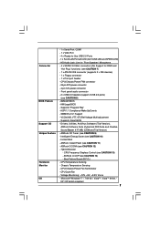
... - SMBIOS 2.3.1 Support - Chassis Temperature Sensing - CPU Frequency Stepless Control (see CAUTION 8) - 8Mb AMI BIOS - Front panel audio connector - 2 x USB 2.0 headers (support 4 USB 2.0 ports) (see CAUTION 13) - ASRock OC Tuner (see CAUTION 7) - 1 x ATA100 IDE connector (supports 2 x IDE devices) - 1 x...4 pin 12V power connector - VCCM, NB, VTT, GTLRef Voltage Multi-adjustment - ASRock OC DNA (see CAUTION 11) - CPU/Chassis/Power Fan Tachometer - AMI Legal BIOS - Connector BIOS Feature Support CD Unique Feature Hardware Monitor OS - 1 x Serial Port: COM1 ...
... - SMBIOS 2.3.1 Support - Chassis Temperature Sensing - CPU Frequency Stepless Control (see CAUTION 8) - 8Mb AMI BIOS - Front panel audio connector - 2 x USB 2.0 headers (support 4 USB 2.0 ports) (see CAUTION 13) - ASRock OC Tuner (see CAUTION 7) - 1 x ATA100 IDE connector (supports 2 x IDE devices) - 1 x...4 pin 12V power connector - VCCM, NB, VTT, GTLRef Voltage Multi-adjustment - ASRock OC DNA (see CAUTION 11) - CPU/Chassis/Power Fan Tachometer - AMI Legal BIOS - Connector BIOS Feature Support CD Unique Feature Hardware Monitor OS - 1 x Serial Port: COM1 ...

User Manual
Page 8
... Ready (EuP ready power supply is required) (see CAUTION 15) * For detailed product information, please visit our website: http://www.asrock.com WARNING Please realize that there is subject to the operating system limitation, the actual memory size may affect your system stability, or ..., including adjusting the setting in overclocking mode. * When you use a FSB533-CPU on this motherboard, it will operate in the BIOS, applying Untied Overclocking Technology, or using the thirdparty overclocking tools. Please read the installation guide of memory modules on page 26 for system...
... Ready (EuP ready power supply is required) (see CAUTION 15) * For detailed product information, please visit our website: http://www.asrock.com WARNING Please realize that there is subject to the operating system limitation, the actual memory size may affect your system stability, or ..., including adjusting the setting in overclocking mode. * When you use a FSB533-CPU on this motherboard, it will operate in the BIOS, applying Untied Overclocking Technology, or using the thirdparty overclocking tools. Please read the installation guide of memory modules on page 26 for system...
User Manual
Page 9
... or damage the CPU. 14. With this utility, you install the PC system. 9 Although this tool and save the new BIOS file to access ASRock Instant Flash. In other complicated flash utility. Just launch this motherboard offers stepless control, it is a revolutionary technology that the USB...share with others. With OC DNA, you resume the system, please check if the CPU fan on the same motherboard. 13. ASRock Instant Flash is a BIOS flash utility embedded in a few clicks without preparing an additional floppy diskette or other words, it is capable of Intelligent Energy Saver...
... or damage the CPU. 14. With this utility, you install the PC system. 9 Although this tool and save the new BIOS file to access ASRock Instant Flash. In other complicated flash utility. Just launch this motherboard offers stepless control, it is a revolutionary technology that the USB...share with others. With OC DNA, you resume the system, please check if the CPU fan on the same motherboard. 13. ASRock Instant Flash is a BIOS flash utility embedded in a few clicks without preparing an additional floppy diskette or other words, it is capable of Intelligent Energy Saver...
User Manual
Page 11
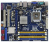
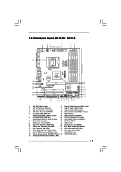
...USB 2.0 Header (USB4_5, Blue) 4 ATX Power Connector (ATXPWR1) 19 System Panel Header (PANEL1, Orange) 5 2 x 240-pin DDR2 DIMM Slots 20 BIOS SPI Chip (Dual Channel: DDRII_1, DDRII_2; Yellow) 21 Floppy Connector (FLOPPY1) 6 2 x 240-pin DDR3 DIMM Slots 22 Print Port Header (LPT1, ...EUP Audio Jumper (EUP_AUDIO1) 11 IDE1 Connector (IDE1, Blue) 28 EUP LAN Jumper (EUP_LAN1) 12 Third SATAII Connector (SATAII_3; 1.3 Motherboard Layout (G41C-GS / G41C-S) 1 23 4 19.8cm (7.8 in) 1 PS2_USB_PWR1 ATX12V2 CPU_FAN1 56 PS2 Mouse PS2 Keyboard COM1 24.4cm (9.6 in) DDR3_B1 (64 bit, ...
...USB 2.0 Header (USB4_5, Blue) 4 ATX Power Connector (ATXPWR1) 19 System Panel Header (PANEL1, Orange) 5 2 x 240-pin DDR2 DIMM Slots 20 BIOS SPI Chip (Dual Channel: DDRII_1, DDRII_2; Yellow) 21 Floppy Connector (FLOPPY1) 6 2 x 240-pin DDR3 DIMM Slots 22 Print Port Header (LPT1, ...EUP Audio Jumper (EUP_AUDIO1) 11 IDE1 Connector (IDE1, Blue) 28 EUP LAN Jumper (EUP_LAN1) 12 Third SATAII Connector (SATAII_3; 1.3 Motherboard Layout (G41C-GS / G41C-S) 1 23 4 19.8cm (7.8 in) 1 PS2_USB_PWR1 ATX12V2 CPU_FAN1 56 PS2 Mouse PS2 Keyboard COM1 24.4cm (9.6 in) DDR3_B1 (64 bit, ...
User Manual
Page 20
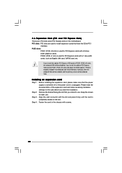
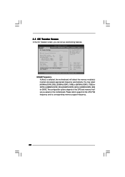
PCI slots: PCI slots are 2 PCI slots and 2 PCI Express slots on PCI Express VGA card to PCIE1 (PCIE x16 slot) and adjust the BIOS options "Primary Graphics Adapter" to [Onboard] and "Share Memory" to [Auto], then the onboard VGA will be enabled, and the primary screen will be onboard ...
PCI slots: PCI slots are 2 PCI slots and 2 PCI Express slots on PCI Express VGA card to PCIE1 (PCIE x16 slot) and adjust the BIOS options "Primary Graphics Adapter" to [Onboard] and "Share Memory" to [Auto], then the onboard VGA will be enabled, and the primary screen will be onboard ...
User Manual
Page 23
... USB 2.0 ports on the I/O panel, there are for AC'97 audio panel. Please follow the instruction in our manual and chassis manual to MIC2_L. Enter BIOS Setup Utility. Connect Mic_IN (MIC) to install your system. 2. B. Connect Audio_R (RIN) to OUT2_R and Audio_L (LIN) to the SATA / SATAII hard disk or the...
... USB 2.0 ports on the I/O panel, there are for AC'97 audio panel. Please follow the instruction in our manual and chassis manual to MIC2_L. Enter BIOS Setup Utility. Connect Mic_IN (MIC) to install your system. 2. B. Connect Audio_R (RIN) to OUT2_R and Audio_L (LIN) to the SATA / SATAII hard disk or the...
User Manual
Page 26
... due to fixed PCI / PCIE buses. You may install SATA / SATAII hard disks on page 8 for internal storage devices. STEP 4: Connect the other end of BIOS setup to set the selection from up to bottom side to the warning on this motherboard for the possible overclocking risk before you to the...
... due to fixed PCI / PCIE buses. You may install SATA / SATAII hard disks on page 8 for internal storage devices. STEP 4: Connect the other end of BIOS setup to set the selection from up to bottom side to the warning on this motherboard for the possible overclocking risk before you to the...
User Manual
Page 27
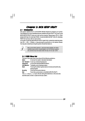
... to choose among the selections on the menu bar, and then press to get into the sub screen. 27 Because the BIOS software is constantly being updated, the following BIOS setup screens and descriptions are for reference purpose only, and they may not exactly match what you see on your system. erating... System Security To set up the computer. You may run the BIOS SETUP UTILITY when you wish to enter the BIOS SETUP UTILITY after POST, restart the system by pressing + + , or by turning the system off and then back on the ...
... to choose among the selections on the menu bar, and then press to get into the sub screen. 27 Because the BIOS software is constantly being updated, the following BIOS setup screens and descriptions are for reference purpose only, and they may not exactly match what you see on your system. erating... System Security To set up the computer. You may run the BIOS SETUP UTILITY when you wish to enter the BIOS SETUP UTILITY after POST, restart the system by pressing + + , or by turning the system off and then back on the ...
User Manual
Page 28
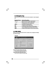
... To bring up the selected screen To display the General Help Screen To load optimal default values for the function description of each navigation key. BIOS Version : G41C-GS P1.00 Processor Type : Intel (R) Core (TM) 2 Duo CPU E8200 @ 2.66GHz (64bit) Processor Speed : 2666MHz Microcode Update : 10676/60C Cache Size : 6144KB Total Memory...
... To bring up the selected screen To display the General Help Screen To load optimal default values for the function description of each navigation key. BIOS Version : G41C-GS P1.00 Processor Type : Intel (R) Core (TM) 2 Duo CPU E8200 @ 2.66GHz (64bit) Processor Speed : 2666MHz Microcode Update : 10676/60C Cache Size : 6144KB Total Memory...
User Manual
Page 29
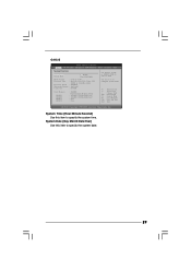
System Date [Day Month/Date/Year] Use this item to specify the system date. 29 BIOS Version : G41C-S P1.00 Processor Type : Intel (R) Core (TM) 2 Duo CPU E8200 @ 2.66GHz (64bit) Processor Speed : 2666MHz Microcode Update : 10676/60C Cache Size : ...Memory DDRII1 DDRII2 DDR3_1 DDR3_2 : 2048MB Dual-Channel Memory Mode : 1024MB/333MHz DDR2_667 : 1024MB/333MHz DDR2_667 : None : None Use [+] or [-] to select a field. G41C-S BIOS SETUP UTILITY Main OC Tweaker Advanced H/W Monitor Boot Security Exit System Overview System Time System Date [14:00:09] [Tue 12/01/2009] Use [Enter...
System Date [Day Month/Date/Year] Use this item to specify the system date. 29 BIOS Version : G41C-S P1.00 Processor Type : Intel (R) Core (TM) 2 Duo CPU E8200 @ 2.66GHz (64bit) Processor Speed : 2666MHz Microcode Update : 10676/60C Cache Size : ...Memory DDRII1 DDRII2 DDR3_1 DDR3_2 : 2048MB Dual-Channel Memory Mode : 1024MB/333MHz DDR2_667 : 1024MB/333MHz DDR2_667 : None : None Use [+] or [-] to select a field. G41C-S BIOS SETUP UTILITY Main OC Tweaker Advanced H/W Monitor Boot Security Exit System Overview System Time System Date [14:00:09] [Tue 12/01/2009] Use [Enter...
User Manual
Page 30
...] or [667MHz DDR3_1333] for DDR3 or [266MHz DDR2_533], [333MHz DDR2_667] or [400MHz DDR2_800] for the CPU FSB frequency and its corresponding memory support frequency. 30 BIOS SETUP UTILITY Main OC Tweaker Advanced H/W Monitor Boot Security Exit OC Tweaker Settings DRAM Frequency DRAM Timing Configuration Ratio CMOS Setting 8 Intel (R) SpeedStep (tm) tech...
...] or [667MHz DDR3_1333] for DDR3 or [266MHz DDR2_533], [333MHz DDR2_667] or [400MHz DDR2_800] for the CPU FSB frequency and its corresponding memory support frequency. 30 BIOS SETUP UTILITY Main OC Tweaker Advanced H/W Monitor Boot Security Exit OC Tweaker Settings DRAM Frequency DRAM Timing Configuration Ratio CMOS Setting 8 Intel (R) SpeedStep (tm) tech...
User Manual
Page 31
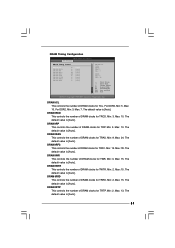
...: 9. Min: 2. Min: 2. DRAM tRRD This controls the number of DRAM clocks for TRTP. Max: 10. Max: 15. The default value is [Auto]. DRAM Timing Configuration BIOS SETUP UTILITY OC Tweaker DRAM Timing Control DRAM tCL 6 DRAM tRCD 6 DRAM tRP 6 DRAM tRAS 15 DRAM tRFC 44 DRAM tWR 6 DRAM tWTR 4 DRAM tRRD...
...: 9. Min: 2. Min: 2. DRAM tRRD This controls the number of DRAM clocks for TRTP. Max: 10. Max: 15. The default value is [Auto]. DRAM Timing Configuration BIOS SETUP UTILITY OC Tweaker DRAM Timing Control DRAM tCL 6 DRAM tRCD 6 DRAM tRP 6 DRAM tRAS 15 DRAM tRFC 44 DRAM tWR 6 DRAM tWTR 4 DRAM tRRD...
User Manual
Page 34
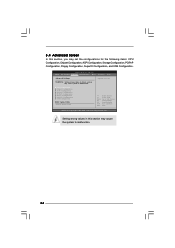
...may set the configurations for CPU WARNING : Setting wrong values in below sections may cause the system to malfunction. 34 BIOS SETUP UTILITY Main OC Tweaker Advanced H/W Monitor Boot Security Exit Advanced Settings Options for the following items: CPU Configuration, ...and USB Configuration. CPU Configuration Chipset Configuration ACPI Configuration Storage Configuration PCIPnP Configuration Floppy Configuration SuperIO Configuration USB Configuration BIOS Update Utility ASRock Instant Flash Select Screen Select Item Enter Go to Sub Screen F1 General Help F9 Load Defaults F10 Save...
...may set the configurations for CPU WARNING : Setting wrong values in below sections may cause the system to malfunction. 34 BIOS SETUP UTILITY Main OC Tweaker Advanced H/W Monitor Boot Security Exit Advanced Settings Options for the following items: CPU Configuration, ...and USB Configuration. CPU Configuration Chipset Configuration ACPI Configuration Storage Configuration PCIPnP Configuration Floppy Configuration SuperIO Configuration USB Configuration BIOS Update Utility ASRock Instant Flash Select Screen Select Item Enter Go to Sub Screen F1 General Help F9 Load Defaults F10 Save...
User Manual
Page 35
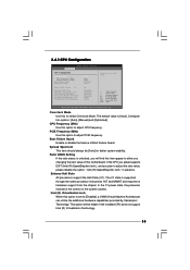
... ESC Select Screen Select Item Change Option General Help Load Defaults Save and Exit Exit v02.54 (C) Copyright 1985-2005, American Megatrends, Inc. 3.4.1 CPU Configuration BIOS SETUP UTILITY Advanced CPU Configuration Overclock Mode CPU Frequency (MHz) PCIE Frequency (MHz) Boot Failure Guard Spread Spectrum Ratio CMOS Setting 8 Enhanced Halt State Intel...
... ESC Select Screen Select Item Change Option General Help Load Defaults Save and Exit Exit v02.54 (C) Copyright 1985-2005, American Megatrends, Inc. 3.4.1 CPU Configuration BIOS SETUP UTILITY Advanced CPU Configuration Overclock Mode CPU Frequency (MHz) PCIE Frequency (MHz) Boot Failure Guard Spread Spectrum Ratio CMOS Setting 8 Enhanced Halt State Intel...
User Manual
Page 37
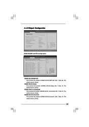
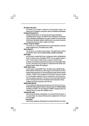
... The default value is [Auto]. 37 The default value is [Auto]. Min: 1. Max: 15. Min: 1. 3.4.2 Chipset Configuration BIOS SETUP UTILITY Advanced Chipset Settings DRAM RCOMP and tRD Configuration DRAM DLL SKEW Configuration Fixed Mode Operation [Enabled] Intelligent Energy Saver Primary Graphics Adapter...General Help Load Defaults Save and Exit Exit v02.54 (C) Copyright 1985-2005, American Megatrends, Inc. DRAM RCOMP and tRD Configuration BIOS SETUP UTILITY Advanced DRAM RCOMP STRENGTH Settings DRAM CH0 RCOMP Settings : 54-0-11-6-6-6-6 DRAM CH0 RCOMP ODT [Auto] DRAM CH0 G0...
... The default value is [Auto]. 37 The default value is [Auto]. Min: 1. Max: 15. Min: 1. 3.4.2 Chipset Configuration BIOS SETUP UTILITY Advanced Chipset Settings DRAM RCOMP and tRD Configuration DRAM DLL SKEW Configuration Fixed Mode Operation [Enabled] Intelligent Energy Saver Primary Graphics Adapter...General Help Load Defaults Save and Exit Exit v02.54 (C) Copyright 1985-2005, American Megatrends, Inc. DRAM RCOMP and tRD Configuration BIOS SETUP UTILITY Advanced DRAM RCOMP STRENGTH Settings DRAM CH0 RCOMP Settings : 54-0-11-6-6-6-6 DRAM CH0 RCOMP ODT [Auto] DRAM CH0 G0...
User Manual
Page 39
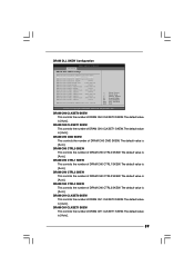
DRAM DLL SKEW Configuration BIOS SETUP UTILITY Advanced DRAM DLL SKEW Settings DRAM CH0 CLKSET0 SKEW Info:0-0-0-0-0-0 DRAM CH0 CLKSET0 SKEW [Auto] DRAM CH0 CLKSET1 SKEW Info:0-0-0-0-0-0 DRAM CH0 CLKSET1 ...
DRAM DLL SKEW Configuration BIOS SETUP UTILITY Advanced DRAM DLL SKEW Settings DRAM CH0 CLKSET0 SKEW Info:0-0-0-0-0-0 DRAM CH0 CLKSET0 SKEW [Auto] DRAM CH0 CLKSET1 SKEW Info:0-0-0-0-0-0 DRAM CH0 CLKSET1 ...
User Manual
Page 41
.... This item will not be used under Windows® VistaTM OS because the driver will be disabled when PCI Sound Card is [Disabled]. Besides the BIOS option, you to adjust DVMT mode. The default value is [DVMT Mode]. The default value is plugged. Front Panel Select [Auto], [Enabled] or [Disabled] for...
.... This item will not be used under Windows® VistaTM OS because the driver will be disabled when PCI Sound Card is [Disabled]. Besides the BIOS option, you to adjust DVMT mode. The default value is [DVMT Mode]. The default value is plugged. Front Panel Select [Auto], [Enabled] or [Disabled] for...
User Manual
Page 42
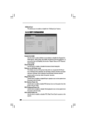
... power state after an unexpected AC/Power loss. PCI Devices Power On Use this item to enable or disable the "OnBoard Lan" feature. 3.4.3 ACPI Configuration BIOS SETUP UTILITY Advanced ACPI Configuration Suspend To RAM Restore on the system from the power-soft-off mode. If you to enable or disable the...
... power state after an unexpected AC/Power loss. PCI Devices Power On Use this item to enable or disable the "OnBoard Lan" feature. 3.4.3 ACPI Configuration BIOS SETUP UTILITY Advanced ACPI Configuration Suspend To RAM Restore on the system from the power-soft-off mode. If you to enable or disable the...


