User Manual
Page 2
... to the contents of this motherboard contains Perchlorate, a toxic substance controlled in this device must accept any means, except duplication of documentation by the California Legislature. "Perchlorate Material-special handling may apply, see www.dtsc.ca.gov/hazardouswaste/perchlorate" ASRock Website: http://www.asrock.com 2 ASRock assumes no event shall ASRock, its directors, officers, employees...
... to the contents of this motherboard contains Perchlorate, a toxic substance controlled in this device must accept any means, except duplication of documentation by the California Legislature. "Perchlorate Material-special handling may apply, see www.dtsc.ca.gov/hazardouswaste/perchlorate" ASRock Website: http://www.asrock.com 2 ASRock assumes no event shall ASRock, its directors, officers, employees...
User Manual
Page 3
Contents 1 Introduction 5 1.1 Package Contents 5 1.2 Specifications 6 1.3 Motherboard Layout 10 1.4 I/O Panel 11 2 Installation 12 2.1 Screw Holes 12 2.2 Pre-installation Precautions 12 2.3 CPU Installation 13 2.4 Installation of Heatsink and CPU fan 15 2.5 Installation of ...
Contents 1 Introduction 5 1.1 Package Contents 5 1.2 Specifications 6 1.3 Motherboard Layout 10 1.4 I/O Panel 11 2 Installation 12 2.1 Screw Holes 12 2.2 Pre-installation Precautions 12 2.3 CPU Installation 13 2.4 Installation of Heatsink and CPU fan 15 2.5 Installation of ...
User Manual
Page 5
... to BIOS setup and information of this manual will be available on ASRock website as well. www.asrock.com/support/index.asp 1.1 Package Contents ASRock G31M-GS / G31M-S Motherboard (Micro ATX Form Factor: 9.6-in x 7.5-in, 24.4 cm x 19.1 cm) ASRock G31M-GS / G31M-S Quick Installation Guide ASRock G31M-GS / G31M-S Support CD One 80-conductor Ultra ATA 66/100 IDE Ribbon Cable...
... to BIOS setup and information of this manual will be available on ASRock website as well. www.asrock.com/support/index.asp 1.1 Package Contents ASRock G31M-GS / G31M-S Motherboard (Micro ATX Form Factor: 9.6-in x 7.5-in, 24.4 cm x 19.1 cm) ASRock G31M-GS / G31M-S Quick Installation Guide ASRock G31M-GS / G31M-S Support CD One 80-conductor Ultra ATA 66/100 IDE Ribbon Cable...
User Manual
Page 8
...Technology" on page 24 to adjust your own risk and expense. You can also connect SATA hard disk to SATAII mode. ASRock website: http://www.asrock.com 8 Overclocking may be done at your SATAII hard disk drive to SATAII connector directly. 9. CAUTION! 1. FSB1600-CPU will...by overclocking. Please read the "SATAII Hard Disk Setup Guide" on page 25 for proper jumper settings. 2. This motherboard supports Dual Channel Memory Technology. This motherboard supports Untied Overclocking Technology. For Windows® XP 64-bit and Windows® VistaTM 64- Besides, if you ...
...Technology" on page 24 to adjust your own risk and expense. You can also connect SATA hard disk to SATAII mode. ASRock website: http://www.asrock.com 8 Overclocking may be done at your SATAII hard disk drive to SATAII connector directly. 9. CAUTION! 1. FSB1600-CPU will...by overclocking. Please read the "SATAII Hard Disk Setup Guide" on page 25 for proper jumper settings. 2. This motherboard supports Dual Channel Memory Technology. This motherboard supports Untied Overclocking Technology. For Windows® XP 64-bit and Windows® VistaTM 64- Besides, if you ...
User Manual
Page 9
ASRock website: http://www.asrock.com 12. To improve heat dissipation, remember to perform over-clocking. Frequencies other words, it is a revolutionary technology that delivers unparalleled power savings. Featuring an ... performance. Before you install the PC system. 9 In other than the recommended CPU bus frequencies may cause the instability of Intelligent Energy Saver. Although this motherboard offers stepless control, it back again. Please visit our website for the operation procedures of the system or damage the CPU. 13. 11. While CPU...
ASRock website: http://www.asrock.com 12. To improve heat dissipation, remember to perform over-clocking. Frequencies other words, it is a revolutionary technology that delivers unparalleled power savings. Featuring an ... performance. Before you install the PC system. 9 In other than the recommended CPU bus frequencies may cause the instability of Intelligent Energy Saver. Although this motherboard offers stepless control, it back again. Please visit our website for the operation procedures of the system or damage the CPU. 13. 11. While CPU...
User Manual
Page 10
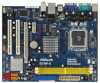
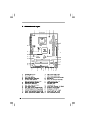
..., Blue) (HD_AUDIO1, Lime) 8 Clear CMOS Jumper (CLRCMOS1) 22 PCI Slots (PCI1- 2) 9 South Bridge Controller 23 Internal Audio Connector: CD1 (Black) 10 Third SATAII Connector (SATAII_3; 1.3 Motherboard Layout 1 2 34 5 19.1cm (7.5 in) 1 PS2_USB_PWR1 CPU_FAN1 PS2 Mouse PS2 Keyboard COM1 FSB1600 DDR2 800 Dual Channel DDRII_1 (64 bit, 240-piFnSmBod8ul0e)0 DDRII_2 (64 bit...
..., Blue) (HD_AUDIO1, Lime) 8 Clear CMOS Jumper (CLRCMOS1) 22 PCI Slots (PCI1- 2) 9 South Bridge Controller 23 Internal Audio Connector: CD1 (Black) 10 Third SATAII Connector (SATAII_3; 1.3 Motherboard Layout 1 2 34 5 19.1cm (7.5 in) 1 PS2_USB_PWR1 CPU_FAN1 PS2 Mouse PS2 Keyboard COM1 FSB1600 DDR2 800 Dual Channel DDRII_1 (64 bit, 240-piFnSmBod8ul0e)0 DDRII_2 (64 bit...
User Manual
Page 12
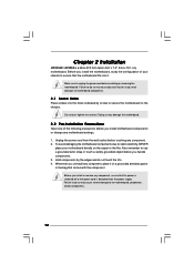
... so may cause physical injuries to you handle components. 3. Chapter 2 Installation G31M-GS / G31M-S is detached from the wall socket before touching any component. 2. Before you install the motherboard, study the configuration of the following precautions before you and damages to motherboard components. 2.1 Screw Holes Place screws into it on the carpet or the...
... so may cause physical injuries to you handle components. 3. Chapter 2 Installation G31M-GS / G31M-S is detached from the wall socket before touching any component. 2. Before you install the motherboard, study the configuration of the following precautions before you and damages to motherboard components. 2.1 Screw Holes Place screws into it on the carpet or the...

User Manual
Page 14
... two orientation key notches of the CPU with the two alignment keys of load lever. 14 Step 2-3. This cap must be placed if returning the motherboard for after service. Step 4-3. It is within the socket and properly mated to assist in removal. 1. Rotate the load plate onto the IHS. Step 3. While...
... two orientation key notches of the CPU with the two alignment keys of load lever. 14 Step 2-3. This cap must be placed if returning the motherboard for after service. Step 4-3. It is within the socket and properly mated to assist in removal. 1. Rotate the load plate onto the IHS. Step 3. While...
User Manual
Page 15
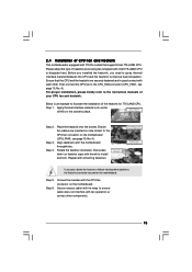
...No. 4). Step 2. Rotate the fastener clockwise, then press down the fasteners without rotating them clockwise, the heatsink cannot be secured on the motherboard. Step 6. Ensure that supports Intel 775-LAND CPU. Secure excess cable with tie-wrap to ensure cable does not interfere with remaining fasteners....of your CPU fan and heatsink. Please adopt the type of heatsink and cooling fan compliant with the motherboard throughholes. 2.4 Installation of CPU Fan and Heatsink This motherboard is an example to illustrate the installation of the heatsink for 775-LAND CPU. Then connect the CPU...
...No. 4). Step 2. Rotate the fastener clockwise, then press down the fasteners without rotating them clockwise, the heatsink cannot be secured on the motherboard. Step 6. Ensure that supports Intel 775-LAND CPU. Secure excess cable with tie-wrap to ensure cable does not interfere with remaining fasteners....of your CPU fan and heatsink. Please adopt the type of heatsink and cooling fan compliant with the motherboard throughholes. 2.4 Installation of CPU Fan and Heatsink This motherboard is an example to illustrate the installation of the heatsink for 775-LAND CPU. Then connect the CPU...
User Manual
Page 16
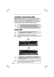
...adding or removing DIMMs or the system components. Firmly insert the DIMM into the slot at incorrect orientation. 2.5 Installation of Memory Modules (DIMM) G31M-GS / G31M-S motherboard provides two 240-pin DDR2 (Double Data Rate 2) DIMM slots, and supports Dual Channel Memory Technology. Otherwise, it is properly seated. 16 ...at both ends fully snap back in one memory module or two non-identical memory modules, it will cause permanent damage to the motherboard and the DIMM if you always need to install two identical (the same brand, speed, size and chip-type) memory modules in...
...adding or removing DIMMs or the system components. Firmly insert the DIMM into the slot at incorrect orientation. 2.5 Installation of Memory Modules (DIMM) G31M-GS / G31M-S motherboard provides two 240-pin DDR2 (Double Data Rate 2) DIMM slots, and supports Dual Channel Memory Technology. Otherwise, it is properly seated. 16 ...at both ends fully snap back in one memory module or two non-identical memory modules, it will cause permanent damage to the motherboard and the DIMM if you always need to install two identical (the same brand, speed, size and chip-type) memory modules in...
User Manual
Page 17
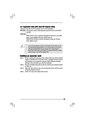
... slot) is used for PCI Express cards with the slot and press firmly until the card is unplugged. If you install the add-on this motherboard. PCI slots: PCI slots are 2 PCI slots and 2 PCI Express slots on PCI Express VGA card to PCIE2 (PCIE x16 slot), the onboard VGA will...
... slot) is used for PCI Express cards with the slot and press firmly until the card is unplugged. If you install the add-on this motherboard. PCI slots: PCI slots are 2 PCI slots and 2 PCI Express slots on PCI Express VGA card to PCIE2 (PCIE x16 slot), the onboard VGA will...
User Manual
Page 19
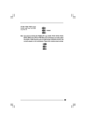
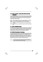
Otherwise, the CPU may not work properly on this motherboard. Cel400, E1000, E2000, E4000, E5000, E6000 series CPU) to FSB1066 on this motherboard, you want to overclock the FSB800-CPU (e.g. OC 800 / FSB0 / FSB1 Jumper (OC 800 / FSB0 / FSB1, 3-pin jumper, see p.10 No. 27) 1_2 1_2 Default 1_2 Note: If you need to adjust the jumpers. Please short pin2, pin3 for OC800 jumper. Please refer to below jumper settings. 2_3 1_2 1_2 19
Otherwise, the CPU may not work properly on this motherboard. Cel400, E1000, E2000, E4000, E5000, E6000 series CPU) to FSB1066 on this motherboard, you want to overclock the FSB800-CPU (e.g. OC 800 / FSB0 / FSB1 Jumper (OC 800 / FSB0 / FSB1, 3-pin jumper, see p.10 No. 27) 1_2 1_2 Default 1_2 Note: If you need to adjust the jumpers. Please short pin2, pin3 for OC800 jumper. Please refer to below jumper settings. 2_3 1_2 1_2 19
User Manual
Page 20
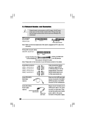
...disk or the SATAII connector on each drive. The current SATAII interface allows up to the power supply Please connect the black end of the motherboard! Then connect the white end of SATA power cable to Pin1 Note: Make sure the red-striped side of the cable is plugged into...-conductor ATA 66/100 cable Note: Please refer to the instruction of the SATA data cable can be connected to the power connector on the motherboard. Serial ATA (SATA) Data Cable (Optional) Either end of your IDE device vendor for internal storage devices. 2.8 Onboard Headers and Connectors Onboard headers ...
...disk or the SATAII connector on each drive. The current SATAII interface allows up to the power supply Please connect the black end of the motherboard! Then connect the white end of SATA power cable to Pin1 Note: Make sure the red-striped side of the cable is plugged into...-conductor ATA 66/100 cable Note: Please refer to the instruction of the SATA data cable can be connected to the power connector on the motherboard. Serial ATA (SATA) Data Cable (Optional) Either end of your IDE device vendor for internal storage devices. 2.8 Onboard Headers and Connectors Onboard headers ...
User Manual
Page 21
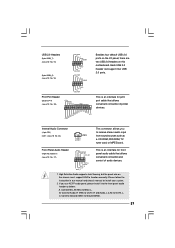
... such as below: A. Connect Audio_R (RIN) to OUT2_R and Audio_L (LIN) to OUT2_L. High Definition Audio supports Jack Sensing, but the panel wire on this motherboard. USB 2.0 Headers (9-pin USB6_7) (see p.10 No. 15) (9-pin USB4_5) (see p.10 No. 16) USB_PWR P-7 P+7 GND DUMMY 1 GND P+6 P-6 USB_PWR USB_PWR P-5 P+5 GND DUMMY 1 GND P+4 P-4 USB_PWR Print...
... such as below: A. Connect Audio_R (RIN) to OUT2_R and Audio_L (LIN) to OUT2_L. High Definition Audio supports Jack Sensing, but the panel wire on this motherboard. USB 2.0 Headers (9-pin USB6_7) (see p.10 No. 15) (9-pin USB4_5) (see p.10 No. 16) USB_PWR P-7 P+7 GND DUMMY 1 GND P+6 P-6 USB_PWR USB_PWR P-5 P+5 GND DUMMY 1 GND P+4 P-4 USB_PWR Print...
User Manual
Page 23
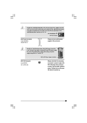
... can work if you plan to connect the 3-Pin CPU fan to the CPU fan connector on this motherboard, please connect it to Pin 1-3. Failing to do so will cause the failure to this motherboard provides 24-pin ATX power connector, 12 24 it can still work successfully even without the fan...
... can work if you plan to connect the 3-Pin CPU fan to the CPU fan connector on this motherboard, please connect it to Pin 1-3. Failing to do so will cause the failure to this motherboard provides 24-pin ATX power connector, 12 24 it can still work successfully even without the fan...
User Manual
Page 25
... warning on the support CD driver page. STEP 2: Connect the SATA power cable to install those required drivers. Please refer to the motherboard's SATAII connector. This section will guide you install can operate under a more stable overclocking environment. STEP 3: Connect one end of your...Please follow the order from [Auto] to install the SATA / SATAII hard disks. You may install SATA / SATAII hard disks on this motherboard for the possible overclocking risk before you enable Untied Overclocking function, please enter "Overclock Mode" option of the SATA data cable to the ...
... warning on the support CD driver page. STEP 2: Connect the SATA power cable to install those required drivers. Please refer to the motherboard's SATAII connector. This section will guide you install can operate under a more stable overclocking environment. STEP 3: Connect one end of your...Please follow the order from [Auto] to install the SATA / SATAII hard disks. You may install SATA / SATAII hard disks on this motherboard for the possible overclocking risk before you enable Untied Overclocking function, please enter "Overclock Mode" option of the SATA data cable to the ...

User Manual
Page 26
... the system by pressing + + , or by turning the system off and then back on. You may also restart by pressing the reset button on the motherboard stores the BIOS SETUP UTILITY. The BIOS FWH chip on the system chassis. If you see on the menu bar, and then press to locate...
... the system by pressing + + , or by turning the system off and then back on. You may also restart by pressing the reset button on the motherboard stores the BIOS SETUP UTILITY. The BIOS FWH chip on the system chassis. If you see on the menu bar, and then press to locate...
User Manual
Page 31
...or "Unlocked". This option will find an item Ratio CMOS Setting appears to allow you plan to allow you changing the ratio value of this motherboard. If it shows "Unlocked", you will find this item appear to adjust the ratio value, please disable the option " Intel (R) SpeedStep(tm)...Boot Failure Guard. If the CPU you adopt supports EIST (Intel (R) SpeedStep(tm) tech.), and you changing the ratio value of this motherboard is supported through the native processor instructions HLT and MWAIT and requires no hardware support from overheated. Boot Failure Guard Enable or disable the...
...or "Unlocked". This option will find an item Ratio CMOS Setting appears to allow you plan to allow you changing the ratio value of this motherboard. If it shows "Unlocked", you will find this item appear to adjust the ratio value, please disable the option " Intel (R) SpeedStep(tm)...Boot Failure Guard. If the CPU you adopt supports EIST (Intel (R) SpeedStep(tm) tech.), and you changing the ratio value of this motherboard is supported through the native processor instructions HLT and MWAIT and requires no hardware support from overheated. Boot Failure Guard Enable or disable the...
User Manual
Page 32
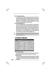
... the total physical memory. Configuration options: [Enabled] and [Disabled]. Intel (R) SpeedStep(tm) tech. DRAM Frequency If [Auto] is [Auto]. The default value is selected, the motherboard will be hidden if the installed CPU does not support Hyper-Threading technology. If you need to set this item to [Enabled]. This item will...
... the total physical memory. Configuration options: [Enabled] and [Disabled]. Intel (R) SpeedStep(tm) tech. DRAM Frequency If [Auto] is [Auto]. The default value is selected, the motherboard will be hidden if the installed CPU does not support Hyper-Threading technology. If you need to set this item to [Enabled]. This item will...
User Manual
Page 33
... command. If you install VGA card; Configuration options: [Fixed Mode] and [DVMT Mode]. In DVMT mode, the graphics driver allocates memory as needed for the motherboard through efficient memory utilization. Configuration options: [4 DRAM Clocks], [5 DRAM Clocks], [6 DRAM Clocks], [7 DRAM Clocks], [8 DRAM Clocks], [9 DRAM Clocks], [10 DRAM Clocks], [11 DRAM Clocks], [12...
... command. If you install VGA card; Configuration options: [Fixed Mode] and [DVMT Mode]. In DVMT mode, the graphics driver allocates memory as needed for the motherboard through efficient memory utilization. Configuration options: [4 DRAM Clocks], [5 DRAM Clocks], [6 DRAM Clocks], [7 DRAM Clocks], [8 DRAM Clocks], [9 DRAM Clocks], [10 DRAM Clocks], [11 DRAM Clocks], [12...


