

User Manual
Page 6
... Package Contents 1 1.2 Speciications 2 1.3 Motherboard Layout 6 1.4 I/O Panel 9 Chapter 2 Installation 11 2.1 Installing the CPU 12 2.2 Installing the CPU Fan and Heatsink 15 2.3 Installation of Memory Modules (DIMM) 16 2.4 Expansion Slots (PCI Express Slots) 18 2.5 Jumpers Setup 20 2.6 Onboard Headers and Connectors 21 2.7 Smart Switches 26 2.8 Dr. Debug 27 2.9 SLITM , 3-Way SLITMand Quad SLITM Operation Guide 29 2.9.1 Installing Two SLITM-Ready Graphics Cards 29 2.9.2 Installing Three SLITM-Ready Graphics Cards 31 2.9.3 Driver Installation and Setup 33 2.10...
... Package Contents 1 1.2 Speciications 2 1.3 Motherboard Layout 6 1.4 I/O Panel 9 Chapter 2 Installation 11 2.1 Installing the CPU 12 2.2 Installing the CPU Fan and Heatsink 15 2.3 Installation of Memory Modules (DIMM) 16 2.4 Expansion Slots (PCI Express Slots) 18 2.5 Jumpers Setup 20 2.6 Onboard Headers and Connectors 21 2.7 Smart Switches 26 2.8 Dr. Debug 27 2.9 SLITM , 3-Way SLITMand Quad SLITM Operation Guide 29 2.9.1 Installing Two SLITM-Ready Graphics Cards 29 2.9.2 Installing Three SLITM-Ready Graphics Cards 31 2.9.3 Driver Installation and Setup 33 2.10...
User Manual
Page 9
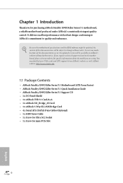
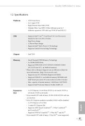
...x ASRock USB 3.1 Card/A+A • 1 x ASRock SLI_Bridge_2S Card • 1 x ASRock 3-Way SLI-2S1S Bridge Card • 4 x Serial ATA (SATA) Data Cables (Optional) • 1 x HDD Saver Cable • 1 x Screw for Ultra M.2 Socket • 1 x Screw for purchasing ASRock Fatal1ty X99X Killer Series/3.1 motherboard, a reliable motherboard produced under ASRock's consistently stringent quality control. In this documentation, Chapter 1 and 2 contains the introduction of this motherboard, please visit our website for speciic information about the model you are using. If you for mini-PCIe Slot...
...x ASRock USB 3.1 Card/A+A • 1 x ASRock SLI_Bridge_2S Card • 1 x ASRock 3-Way SLI-2S1S Bridge Card • 4 x Serial ATA (SATA) Data Cables (Optional) • 1 x HDD Saver Cable • 1 x Screw for Ultra M.2 Socket • 1 x Screw for purchasing ASRock Fatal1ty X99X Killer Series/3.1 motherboard, a reliable motherboard produced under ASRock's consistently stringent quality control. In this documentation, Chapter 1 and 2 contains the introduction of this motherboard, please visit our website for speciic information about the model you are using. If you for mini-PCIe Slot...

User Manual
Page 12
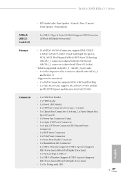
... PCI Express module up to Gen3 x4 (32 Gb/s) Connector • 1 x COM Port Header • 1 x TPM Header • 1 x Power LED Header • 2 x CPU Fan Connectors (1 x 4-pin, 1 x 3-pin) • 3 x Chassis Fan Connectors (1 x 4-pin, 2 x 3-pin) (Smart Fan Speed Control) • 1 x Power Fan Connector (3-pin) • 1 x 24 pin ATX Power Connector • 1 x 8 pin 12V Power Connector (Hi-Density Power Connector) • 1 x HDD Saver Connector • 1 x PCIe Power Connector • 1 x Front Panel Audio Connector • 1 x hunderbolt AIC Connector • 2 x USB 2.0 Headers (support...
... PCI Express module up to Gen3 x4 (32 Gb/s) Connector • 1 x COM Port Header • 1 x TPM Header • 1 x Power LED Header • 2 x CPU Fan Connectors (1 x 4-pin, 1 x 3-pin) • 3 x Chassis Fan Connectors (1 x 4-pin, 2 x 3-pin) (Smart Fan Speed Control) • 1 x Power Fan Connector (3-pin) • 1 x 24 pin ATX Power Connector • 1 x 8 pin 12V Power Connector (Hi-Density Power Connector) • 1 x HDD Saver Connector • 1 x PCIe Power Connector • 1 x Front Panel Audio Connector • 1 x hunderbolt AIC Connector • 2 x USB 2.0 Headers (support...

User Manual
Page 13
.... You can use . 5 English Fatal1ty X99X Killer/3.1 Series BIOS Feature • 1 x Power Switch with LED • 1 x Reset Switch with LED • 1 x BIOS Selection Switch • 2 x 128Mb AMI UEFI Legal BIOS with overclocking, including adjusting the setting in the BIOS, applying Untied Overclocking Technology, or using third-party overclocking tools. It should be less than 4GB for the reservation for possible damage caused by CPU temperature) • CPU/Chassis Fan multi-speed control • Voltage monitoring: +12V, +5V, +3.3V, CPU Input Voltage, CPU Internal Voltages OS...
.... You can use . 5 English Fatal1ty X99X Killer/3.1 Series BIOS Feature • 1 x Power Switch with LED • 1 x Reset Switch with LED • 1 x BIOS Selection Switch • 2 x 128Mb AMI UEFI Legal BIOS with overclocking, including adjusting the setting in the BIOS, applying Untied Overclocking Technology, or using third-party overclocking tools. It should be less than 4GB for the reservation for possible damage caused by CPU temperature) • CPU/Chassis Fan multi-speed control • Voltage monitoring: +12V, +5V, +3.3V, CPU Input Voltage, CPU Internal Voltages OS...

User Manual
Page 15
... SATA3 Connectors (SATA3_1_4) 17 SATA3 Connectors (SATA3_2_5) 18 SATA Express Connector (SATAE_1) 19 Power LED Header (PLED1) 20 Chassis Speaker Header (SPEAKER1) 21 System Panel Header (PANEL1) 22 Power Switch (PWRBTN1) 23 HDD Saver Connector (SATA_PWR_1) 24 Reset Switch (RSTBTN1) 25 Chassis Fan Connector (CHA_FAN2) 26 Chassis Fan Connector (CHA_FAN1) 27 USB 2.0 Header (USB3_4) 28 USB 2.0 Header (USB5_6) 29 BIOS Selection Switch (BIOS_SEL1) 30 Clear CMOS Jumper (CLRCMOS1) 31 COM Port Header (COM1) 32 hunderbolt AIC Connector (TBT1) 33 TPM Header (TPMS1) 34 Front Panel Audio Header (HD_AUDIO1...
... SATA3 Connectors (SATA3_1_4) 17 SATA3 Connectors (SATA3_2_5) 18 SATA Express Connector (SATAE_1) 19 Power LED Header (PLED1) 20 Chassis Speaker Header (SPEAKER1) 21 System Panel Header (PANEL1) 22 Power Switch (PWRBTN1) 23 HDD Saver Connector (SATA_PWR_1) 24 Reset Switch (RSTBTN1) 25 Chassis Fan Connector (CHA_FAN2) 26 Chassis Fan Connector (CHA_FAN1) 27 USB 2.0 Header (USB3_4) 28 USB 2.0 Header (USB5_6) 29 BIOS Selection Switch (BIOS_SEL1) 30 Clear CMOS Jumper (CLRCMOS1) 31 COM Port Header (COM1) 32 hunderbolt AIC Connector (TBT1) 33 TPM Header (TPMS1) 34 Front Panel Audio Header (HD_AUDIO1...

User Manual
Page 33
... enhance network security, protects digital identities, and ensures platform integrity. Fatal1ty X99X Killer/3.1 Series HDD Saver Connector (4-pin SATA_PWR_1) (see p.6, No. 23) hunderbolt AIC Connector (5-pin TBT1) (see p.6, No. 32) Serial Port Header (9-pin COM1) (see p.6, No. 33) 1 GN D SMB_CLK_MAIN SMB_DATA_MAIN LAD2 LAD1 GN D S_PWRDWN # SERIRQ # GND his COM1 header supports a serial port module. TPM Header (17-pin TPMS1) (see p.6, No. 31) Please connect the HDD Saver 1 Cable to manage the power state of HDD.
... enhance network security, protects digital identities, and ensures platform integrity. Fatal1ty X99X Killer/3.1 Series HDD Saver Connector (4-pin SATA_PWR_1) (see p.6, No. 23) hunderbolt AIC Connector (5-pin TBT1) (see p.6, No. 32) Serial Port Header (9-pin COM1) (see p.6, No. 33) 1 GN D SMB_CLK_MAIN SMB_DATA_MAIN LAD2 LAD1 GN D S_PWRDWN # SERIRQ # GND his COM1 header supports a serial port module. TPM Header (17-pin TPMS1) (see p.6, No. 31) Please connect the HDD Saver 1 Cable to manage the power state of HDD.

User Manual
Page 35
... SATA devices. If the problem still exists, please clear CMOS and try using another VGA card. Fatal1ty X99X Killer/3.1 Series 2.8 Dr. Debug Dr. Debug is installed correctly and then clear CMOS. 0d Problem related to memory, VGA card or other devices. Please clear CMOS, re-install the memory and VGA card, and remove other slots. Please re-install the CPU and memory then clear CMOS. Please re-install the CPU and memory. Please see the diagrams below for reading the Dr. Debug codes. Please re-install PCI-E devices or try using other memory...
... SATA devices. If the problem still exists, please clear CMOS and try using another VGA card. Fatal1ty X99X Killer/3.1 Series 2.8 Dr. Debug Dr. Debug is installed correctly and then clear CMOS. 0d Problem related to memory, VGA card or other devices. Please clear CMOS, re-install the memory and VGA card, and remove other slots. Please re-install the CPU and memory then clear CMOS. Please re-install the CPU and memory. Please see the diagrams below for reading the Dr. Debug codes. Please re-install PCI-E devices or try using other memory...

User Manual
Page 42
... identical PCI Express x16 graphics cards. If you to install up to use identical CrossFireXTM-ready graphics cards that are properly seated on the slots. Make sure that your graphics card vendor for details. 4. Please refer to PCIE3 slot. Download the drivers from the AMD's website: www.amd.com 3. Please refer to AMD graphics card manuals for detailed installation guide. 2.10.1 Installing Two CrossFireXTM-Ready Graphics Cards Step 1 Insert one graphics card into PCIE1 slot and the other graphics card...
... identical PCI Express x16 graphics cards. If you to install up to use identical CrossFireXTM-ready graphics cards that are properly seated on the slots. Make sure that your graphics card vendor for details. 4. Please refer to PCIE3 slot. Download the drivers from the AMD's website: www.amd.com 3. Please refer to AMD graphics card manuals for detailed installation guide. 2.10.1 Installing Two CrossFireXTM-Ready Graphics Cards Step 1 Insert one graphics card into PCIE1 slot and the other graphics card...

User Manual
Page 45
.... English 37 Step 3 Install the required drivers and CATALYST Control Center then restart your computer and boot into OS. AMD Catalyst Control Center Step 4 Double-click the AMD Catalyst Control Center icon in your graphics card and click Apply. We recommend using this utility to uninstall any VGA drivers installed in the Windows® system tray. Please check AMD's website for AMD driver updates. Fatal1ty X99X Killer/3.1 Series 2.10.3 Driver Installation and Setup Step 1 Power on your computer...
.... English 37 Step 3 Install the required drivers and CATALYST Control Center then restart your computer and boot into OS. AMD Catalyst Control Center Step 4 Double-click the AMD Catalyst Control Center icon in your graphics card and click Apply. We recommend using this utility to uninstall any VGA drivers installed in the Windows® system tray. Please check AMD's website for AMD driver updates. Fatal1ty X99X Killer/3.1 Series 2.10.3 Driver Installation and Setup Step 1 Power on your computer...

User Manual
Page 52
....com/kb/2720599/en-us 44 English If the Main Menu does not appear automatically, locate and double click on the support CD driver page. Drivers Menu he drivers compatible to display the menu. he CD automatically displays the Main Menu if "AUTORUN" is enabled in the Support CD to your CD-ROM drive. Chapter 3 Software and Utilities Operation 3.1 Installing Drivers he Support CD that comes with the motherboard contains necessary drivers and useful utilities that the motherboard supports.
....com/kb/2720599/en-us 44 English If the Main Menu does not appear automatically, locate and double click on the support CD driver page. Drivers Menu he drivers compatible to display the menu. he CD automatically displays the Main Menu if "AUTORUN" is enabled in the Support CD to your CD-ROM drive. Chapter 3 Software and Utilities Operation 3.1 Installing Drivers he Support CD that comes with the motherboard contains necessary drivers and useful utilities that the motherboard supports.

User Manual
Page 96
...driver ater entering the OS (USB 3.0 is enabled in BIOS). Legacy USB 3 Support Enable or disable Legacy OS Support for USB 2.0 devices. Intel USB 3.0 Mode Select Intel® USB 3.0 controller mode. Legacy USB Support Enable or disable Legacy OS Support for USB 3 devices. Set [Enabled] to keep the USB 3.0 driver enabled ater rebooting (USB 3.0 is disabled in BIOS). Select UEFI Setup Only to use USB devices under the UEFI setup and Windows/Linux operating systems only. 88 English 4.4.6 USB Coniguration USB Controller Enable or disable all the USB ports. Set [Smart Auto...
...driver ater entering the OS (USB 3.0 is enabled in BIOS). Legacy USB 3 Support Enable or disable Legacy OS Support for USB 2.0 devices. Intel USB 3.0 Mode Select Intel® USB 3.0 controller mode. Legacy USB Support Enable or disable Legacy OS Support for USB 3 devices. Set [Enabled] to keep the USB 3.0 driver enabled ater rebooting (USB 3.0 is disabled in BIOS). Select UEFI Setup Only to use USB devices under the UEFI setup and Windows/Linux operating systems only. 88 English 4.4.6 USB Coniguration USB Controller Enable or disable all the USB ports. Set [Smart Auto...

User Manual
Page 100
... support CD, Easy Driver Installer is a handy tool in RAID mode. Boot Manager Boot Manager is recommended to proceed the re-detection for the dual OS platform/multi-OS platform users to easily customize and manage the boot menu. *Please connect more than one boot devices to your system via the HDD Saver application under your SATA Power connection. Please setup network coniguration before using UEFI Tech Service. Easy Driver Installer For users that installs the LAN driver to use...
... support CD, Easy Driver Installer is a handy tool in RAID mode. Boot Manager Boot Manager is recommended to proceed the re-detection for the dual OS platform/multi-OS platform users to easily customize and manage the boot menu. *Please connect more than one boot devices to your system via the HDD Saver application under your SATA Power connection. Please setup network coniguration before using UEFI Tech Service. Easy Driver Installer For users that installs the LAN driver to use...

User Manual
Page 102
Network Coniguration Use this to download the UEFI irmware. UEFI Download Server Select a server to conigure internet connection settings for Internet Flash. Load User Default Load previously saved user defaults. 94 English Internet Setting Enable or disable sound efects in the setup utility. Save User Default Type a proile name and press enter to save your settings as user default.
Network Coniguration Use this to download the UEFI irmware. UEFI Download Server Select a server to conigure internet connection settings for Internet Flash. Load User Default Load previously saved user defaults. 94 English Internet Setting Enable or disable sound efects in the setup utility. Save User Default Type a proile name and press enter to save your settings as user default.

Quick Installation Guide
Page 6
... SATA3 Connectors (SATA3_1_4) 17 SATA3 Connectors (SATA3_2_5) 18 SATA Express Connector (SATAE_1) 19 Power LED Header (PLED1) 20 Chassis Speaker Header (SPEAKER1) 21 System Panel Header (PANEL1) 22 Power Switch (PWRBTN1) 23 HDD Saver Connector (SATA_PWR_1) 24 Reset Switch (RSTBTN1) 25 Chassis Fan Connector (CHA_FAN2) 26 Chassis Fan Connector (CHA_FAN1) 27 USB 2.0 Header (USB3_4) 28 USB 2.0 Header (USB5_6) 29 BIOS Selection Switch (BIOS_SEL1) 30 Clear CMOS Jumper (CLRCMOS1) 31 COM Port Header (COM1) 32 hunderbolt AIC Connector (TBT1) 33 TPM Header (TPMS1) 34 Front Panel Audio Header (HD_AUDIO1...
... SATA3 Connectors (SATA3_1_4) 17 SATA3 Connectors (SATA3_2_5) 18 SATA Express Connector (SATAE_1) 19 Power LED Header (PLED1) 20 Chassis Speaker Header (SPEAKER1) 21 System Panel Header (PANEL1) 22 Power Switch (PWRBTN1) 23 HDD Saver Connector (SATA_PWR_1) 24 Reset Switch (RSTBTN1) 25 Chassis Fan Connector (CHA_FAN2) 26 Chassis Fan Connector (CHA_FAN1) 27 USB 2.0 Header (USB3_4) 28 USB 2.0 Header (USB5_6) 29 BIOS Selection Switch (BIOS_SEL1) 30 Clear CMOS Jumper (CLRCMOS1) 31 COM Port Header (COM1) 32 hunderbolt AIC Connector (TBT1) 33 TPM Header (TPMS1) 34 Front Panel Audio Header (HD_AUDIO1...
Quick Installation Guide
Page 10
... cards and CPU support list on ASRock's website without notice. ASRock website http://www.asrock.com. 1.1 Package Contents • ASRock Fatal1ty X99X Killer Series/3.1 Motherboard (ATX Form Factor) • ASRock Fatal1ty X99X Killer Series/3.1 Quick Installation Guide • ASRock Fatal1ty X99X Killer Series/3.1 Support CD • 1 x I/O Panel Shield • 1 x ASRock USB 3.1 Card/A+A • 1 x ASRock SLI_Bridge_2S Card • 1 x ASRock 3-Way SLI-2S1S Bridge Card • 4 x Serial ATA (SATA) Data Cables (Optional) • 1 x HDD Saver Cable • 1 x Screw for Ultra M.2 Socket...
... cards and CPU support list on ASRock's website without notice. ASRock website http://www.asrock.com. 1.1 Package Contents • ASRock Fatal1ty X99X Killer Series/3.1 Motherboard (ATX Form Factor) • ASRock Fatal1ty X99X Killer Series/3.1 Quick Installation Guide • ASRock Fatal1ty X99X Killer Series/3.1 Support CD • 1 x I/O Panel Shield • 1 x ASRock USB 3.1 Card/A+A • 1 x ASRock SLI_Bridge_2S Card • 1 x ASRock 3-Way SLI-2S1S Bridge Card • 4 x Serial ATA (SATA) Data Cables (Optional) • 1 x HDD Saver Cable • 1 x Screw for Ultra M.2 Socket...
Quick Installation Guide
Page 11
...; 3 x PCI Express 3.0 x16 Slots (PCIE1 @ x16 mode; Fatal1ty X99X Killer/3.1 Series 1.2 Speciications Platform • ATX Form Factor • 2oz Copper PCB • High Density Glass Fabric PCB • Multiple Filter Cap (MFC) (Filter diferent noise by 3 diferent capacitors: DIP solid cap, POSCAP and MLCC) CPU • Supports Intel® CoreTM i7 and Xeon® 18-Core Processors Family for the LGA 2011-3 Socket • Digi Power...
...; 3 x PCI Express 3.0 x16 Slots (PCIE1 @ x16 mode; Fatal1ty X99X Killer/3.1 Series 1.2 Speciications Platform • ATX Form Factor • 2oz Copper PCB • High Density Glass Fabric PCB • Multiple Filter Cap (MFC) (Filter diferent noise by 3 diferent capacitors: DIP solid cap, POSCAP and MLCC) CPU • Supports Intel® CoreTM i7 and Xeon® 18-Core Processors Family for the LGA 2011-3 Socket • Digi Power...
Quick Installation Guide
Page 13
... Killer/3.1 Series • HD Audio Jacks: Rear Speaker / Central / Bass / Line in / Front Speaker / Microphone ASRock USB 3.1 Card/A+A • 2 x USB 3.1 Type-A Ports (10 Gb/s) (Supports ESD Protection (ASRock Full Spike Protection)) Storage • 10 x SATA3 6.0 Gb/s Connectors, support RAID (RAID 0, RAID 1, RAID 5, RAID 10 and Intel Rapid Storage 13), NCQ, AHCI, Hot Plug and ASRock HDD Saver Technology (SSATA3_3 connector is shared with the eSATA port) (SSATA3_2 connector is shared with Ultra M.2 Socket) * RAID is supported on SATA3_0 ~ SATA3_5 ports only. • 1 x SATA Express...
... Killer/3.1 Series • HD Audio Jacks: Rear Speaker / Central / Bass / Line in / Front Speaker / Microphone ASRock USB 3.1 Card/A+A • 2 x USB 3.1 Type-A Ports (10 Gb/s) (Supports ESD Protection (ASRock Full Spike Protection)) Storage • 10 x SATA3 6.0 Gb/s Connectors, support RAID (RAID 0, RAID 1, RAID 5, RAID 10 and Intel Rapid Storage 13), NCQ, AHCI, Hot Plug and ASRock HDD Saver Technology (SSATA3_3 connector is shared with the eSATA port) (SSATA3_2 connector is shared with Ultra M.2 Socket) * RAID is supported on SATA3_0 ~ SATA3_5 ports only. • 1 x SATA Express...

Quick Installation Guide
Page 29
... connector to this connector via the GPIO cable. Please connect a hunderbolt™ add-in card (AIC) to manage the power state of HDD. RRXD1 DDTR#1 DDSR#1 CCTS#1 1 RRI#1 RRTS#1 GND TTXD1 DDCD#1 his connector supports Trusted Platform Module (TPM) system, which can securely store keys, digital certiicates, passwords, and data. Fatal1ty X99X Killer/3.1 Series HDD Saver Connector (4-pin SATA_PWR_1) (see p.1, No. 23) hunderbolt AIC Connector (5-pin TBT1) (see p.1, No. 32) Serial Port Header (9-pin...
... connector to this connector via the GPIO cable. Please connect a hunderbolt™ add-in card (AIC) to manage the power state of HDD. RRXD1 DDTR#1 DDSR#1 CCTS#1 1 RRI#1 RRTS#1 GND TTXD1 DDCD#1 his connector supports Trusted Platform Module (TPM) system, which can securely store keys, digital certiicates, passwords, and data. Fatal1ty X99X Killer/3.1 Series HDD Saver Connector (4-pin SATA_PWR_1) (see p.1, No. 23) hunderbolt AIC Connector (5-pin TBT1) (see p.1, No. 32) Serial Port Header (9-pin...

Quick Installation Guide
Page 31
... PCI-E devices. Please re-install PCI-E devices or try using other memory modules. A7 Problem related to memory. If the problem still exists, please clear CMOS and try removing all PCI-E devices or try using another VGA card. English 27 Please re-install the memory and CPU. b0 Problem related to IDE or SATA devices. Fatal1ty X99X Killer/3.1 Series 2.8 Dr. Debug Dr. Debug is installed correctly and then clear CMOS. 0d Problem related to memory, VGA card or other devices. Please press reset or clear CMOS. 92 - 99 Problem related to memory. Code...
... PCI-E devices. Please re-install PCI-E devices or try using other memory modules. A7 Problem related to memory. If the problem still exists, please clear CMOS and try removing all PCI-E devices or try using another VGA card. English 27 Please re-install the memory and CPU. b0 Problem related to IDE or SATA devices. Fatal1ty X99X Killer/3.1 Series 2.8 Dr. Debug Dr. Debug is installed correctly and then clear CMOS. 0d Problem related to memory, VGA card or other devices. Please press reset or clear CMOS. 92 - 99 Problem related to memory. Code...

RAID Installation Guide
Page 7
... for all models. Press [Enter] to complete the process. STEP 4: Install Windows® 8.1 / 8.1 64-bit / 8 / 8 64-bit / 7 / 7 64-bit OS on how to [RAID]. STEP 1: Setting the BIOS RAID Items After installing the hard disk drives, please set the option SATA Mode Selection to set RAID coniguration. Plug in UEFI setup. Follow the onscreen instruction to conirm the selection. STEP 3: Set RAID coniguration Please refer to install Windows® 8.1 / 8.1 64-bit /8 / 8 64-bit / 7 / 7 64-bit OS on your system. 7 Boot your USB storage device with RAID functions...
... for all models. Press [Enter] to complete the process. STEP 4: Install Windows® 8.1 / 8.1 64-bit / 8 / 8 64-bit / 7 / 7 64-bit OS on how to [RAID]. STEP 1: Setting the BIOS RAID Items After installing the hard disk drives, please set the option SATA Mode Selection to set RAID coniguration. Plug in UEFI setup. Follow the onscreen instruction to conirm the selection. STEP 3: Set RAID coniguration Please refer to install Windows® 8.1 / 8.1 64-bit /8 / 8 64-bit / 7 / 7 64-bit OS on your system. 7 Boot your USB storage device with RAID functions...


