
User Manual
Page 2
...damages (including damages for loss of proits, loss of business, loss of data, interruption of business and the like), even if ASRock has been advised of the possibility of merchantability or itness for a particular purpose. Operation is subject to change without written consent of... for any errors or omissions that may apply, see www.dtsc.ca.gov/hazardouswaste/ perchlorate" ASRock Website: http://www.asrock.com Products and corporate names appearing in this motherboard contains Perchlorate, a toxic substance controlled in this device must accept any means, except duplication of...
...damages (including damages for loss of proits, loss of business, loss of data, interruption of business and the like), even if ASRock has been advised of the possibility of merchantability or itness for a particular purpose. Operation is subject to change without written consent of... for any errors or omissions that may apply, see www.dtsc.ca.gov/hazardouswaste/ perchlorate" ASRock Website: http://www.asrock.com Products and corporate names appearing in this motherboard contains Perchlorate, a toxic substance controlled in this device must accept any means, except duplication of...

User Manual
Page 6
Contents Chapter 1 Introduction 1 1.1 Package Contents 1 1.2 Speciications 2 1.3 Motherboard Layout 6 1.4 I/O Panel 8 Chapter 2 Installation 10 2.1 Installing the CPU 11 2.2 Installing the CPU Fan and Heatsink 14 2.3 Installation of Memory Modules (DIMM) 15 2.4 Expansion Slots (PCI ...
Contents Chapter 1 Introduction 1 1.1 Package Contents 1 1.2 Speciications 2 1.3 Motherboard Layout 6 1.4 I/O Panel 8 Chapter 2 Installation 10 2.1 Installing the CPU 11 2.2 Installing the CPU Fan and Heatsink 14 2.3 Installation of Memory Modules (DIMM) 15 2.4 Expansion Slots (PCI ...

User Manual
Page 9
... installation guides. ASRock website http://www.asrock.com. 1.1 Package Contents • ASRock Fatal1ty X99M Killer Series Motherboard (Micro ATX Form Factor) • ASRock Fatal1ty X99M Killer Series Quick Installation Guide • ASRock Fatal1ty X99M Killer Series Support CD • 1 x I/O Panel Shield • 1 x ASRock SLI_Bridge Card • 2 x Serial ATA (SATA) Data Cables (Optional) • 1 x HDD Saver Cable • 1 x Screw for purchasing ASRock Fatal1ty X99M Killer Series motherboard, a reliable motherboard produced under ASRock's consistently stringent...
... installation guides. ASRock website http://www.asrock.com. 1.1 Package Contents • ASRock Fatal1ty X99M Killer Series Motherboard (Micro ATX Form Factor) • ASRock Fatal1ty X99M Killer Series Quick Installation Guide • ASRock Fatal1ty X99M Killer Series Support CD • 1 x I/O Panel Shield • 1 x ASRock SLI_Bridge Card • 2 x Serial ATA (SATA) Data Cables (Optional) • 1 x HDD Saver Cable • 1 x Screw for purchasing ASRock Fatal1ty X99M Killer Series motherboard, a reliable motherboard produced under ASRock's consistently stringent...
User Manual
Page 14
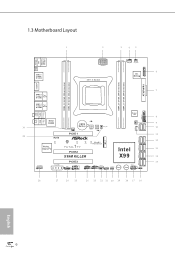
1.3 Motherboard Layout 1 2 3 45 USB 2.0 T: USB1 B: USB2 PS2 Keyboard /Mouse CLRC ...IN USB3_5_6 Center: REAR SPK Bottom: Optical SPDIF Super I/O 8 Top: Center: FRONT Bottom: MIC IN 30 Killer E2200 PWR_FAN1 CMOS Battery BIOS_A_LED A 128Mb BIOS BIOS_A 128Mb BIOS BIOS_B BIOS_B_LED B BIOS_SEL1 CHA_FAN2 SATA_PWR_1 S_SATA3_0_1 1 9 ...M.2 CT5 CT4 CT3 CT2 CT1 PCIe Gen3 x4 Purity SoundTM 2 1 FATAL TY PCIE2 Intel 13 SATA3_0_3 SATA3_1_4 X99M KILLER X99 14 SATA3_2_5 HD_AUDIO1 1 PCIE_PWR1 PCIE3 TBT1 COM1 1 1 USB5_6 USB7_8 1 1 CHA_FAN1 SPEAKER1 1 CLRMOS1 1...
1.3 Motherboard Layout 1 2 3 45 USB 2.0 T: USB1 B: USB2 PS2 Keyboard /Mouse CLRC ...IN USB3_5_6 Center: REAR SPK Bottom: Optical SPDIF Super I/O 8 Top: Center: FRONT Bottom: MIC IN 30 Killer E2200 PWR_FAN1 CMOS Battery BIOS_A_LED A 128Mb BIOS BIOS_A 128Mb BIOS BIOS_B BIOS_B_LED B BIOS_SEL1 CHA_FAN2 SATA_PWR_1 S_SATA3_0_1 1 9 ...M.2 CT5 CT4 CT3 CT2 CT1 PCIe Gen3 x4 Purity SoundTM 2 1 FATAL TY PCIE2 Intel 13 SATA3_0_3 SATA3_1_4 X99M KILLER X99 14 SATA3_2_5 HD_AUDIO1 1 PCIE_PWR1 PCIE3 TBT1 COM1 1 1 USB5_6 USB7_8 1 1 CHA_FAN1 SPEAKER1 1 CLRMOS1 1...
User Manual
Page 18
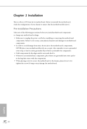
...please do not touch the ICs. • Whenever you uninstall any motherboard settings. • Make sure to ensure that comes with the components. • When placing screws to secure the motherboard to the motherboard's components, NEVER place your chassis to unplug the power cord before installing... • Hold components by the edges and do not overtighten the screws! Before you install the motherboard, study the coniguration of the following precautions before you install motherboard components or change any components, place them on a grounded anti-static pad or in the bag that...
...please do not touch the ICs. • Whenever you uninstall any motherboard settings. • Make sure to ensure that comes with the components. • When placing screws to secure the motherboard to the motherboard's components, NEVER place your chassis to unplug the power cord before installing... • Hold components by the edges and do not overtighten the screws! Before you install the motherboard, study the coniguration of the following precautions before you install motherboard components or change any components, place them on a grounded anti-static pad or in the bag that...

User Manual
Page 21
he cover must be placed if you wish to return the motherboard for ater service. 13 6 7 A B 8 Fatal1ty X99M Killer Series A B English Please save and replace the cover if the processor is removed.
he cover must be placed if you wish to return the motherboard for ater service. 13 6 7 A B 8 Fatal1ty X99M Killer Series A B English Please save and replace the cover if the processor is removed.

User Manual
Page 23
...allowed to install identical (the same brand, speed, size and chip-type) DDR4 DIMM pairs. 2. It is activated. otherwise, this motherboard and DIMM may be damaged. 3. If three memory modules are installed in the DDR4 DIMM slots, then Dual Channel Memory Technology is ...orientation. It will cause permanent damage to the motherboard and the DIMM if you always need to install a DDR, DDR2 or DDR3 memory module into the slot at incorrect orientation. Fatal1ty X99M Killer Series 2.3 Installation of Memory Modules (DIMM) his motherboard provides four 284-pin DDR4 (Double Data Rate...
...allowed to install identical (the same brand, speed, size and chip-type) DDR4 DIMM pairs. 2. It is activated. otherwise, this motherboard and DIMM may be damaged. 3. If three memory modules are installed in the DDR4 DIMM slots, then Dual Channel Memory Technology is ...orientation. It will cause permanent damage to the motherboard and the DIMM if you always need to install a DDR, DDR2 or DDR3 memory module into the slot at incorrect orientation. Fatal1ty X99M Killer Series 2.3 Installation of Memory Modules (DIMM) his motherboard provides four 284-pin DDR4 (Double Data Rate...

User Manual
Page 25
... x16 x8 N/A For a better thermal environment, please connect a chassis fan to the motherboard's chassis fan connector (CHA_FAN1 or CHA_FAN2) when using multiple graphics cards. English 17 Fatal1ty X99M Killer Series 2.4 Expansion Slots (PCI Express Slots) here are 3 PCI Express slots on the motherboard. PCIe slots: PCIE1 (PCIe 3.0 x16 slot) is used for PCI Express x16...
... x16 x8 N/A For a better thermal environment, please connect a chassis fan to the motherboard's chassis fan connector (CHA_FAN1 or CHA_FAN2) when using multiple graphics cards. English 17 Fatal1ty X99M Killer Series 2.4 Expansion Slots (PCI Express Slots) here are 3 PCI Express slots on the motherboard. PCIe slots: PCIE1 (PCIe 3.0 x16 slot) is used for PCI Express x16...

User Manual
Page 27
... assignments are NOT jumpers. he LED is on the chassis front panel. Fatal1ty X99M Killer Series 2.6 Onboard Headers and Connectors Onboard headers and connectors are matched correctly. PWRBTN (Power Switch): Connect to the pin assignments below. RESET (Reset Switch): Connect to the motherboard. Note the positive and negative pins before connecting the cables. Do...
... assignments are NOT jumpers. he LED is on the chassis front panel. Fatal1ty X99M Killer Series 2.6 Onboard Headers and Connectors Onboard headers and connectors are matched correctly. PWRBTN (Power Switch): Connect to the pin assignments below. RESET (Reset Switch): Connect to the motherboard. Note the positive and negative pins before connecting the cables. Do...

User Manual
Page 28
.... 23) USB 3.0 Header (19-pin USB3_5_6) (see p.6, No. 15) SATA3_0 S_SATA3_2 S_SATA3_0 1 PLEDPLED+ PLED+ SATA3_3 S_SATA3_3 S_SATA3_1 Please connect the chassis power LED to this motherboard. hese ten SATA3 connectors support SATA data cables for internal storage devices with up to indicate the system's power status. If the eSATA port on... on the I /O has been connected, the internal S_SATA3_3 will not function. * RAID is one header on the rear I /O panel, there are two headers on this motherboard.
.... 23) USB 3.0 Header (19-pin USB3_5_6) (see p.6, No. 15) SATA3_0 S_SATA3_2 S_SATA3_0 1 PLEDPLED+ PLED+ SATA3_3 S_SATA3_3 S_SATA3_1 Please connect the chassis power LED to this motherboard. hese ten SATA3 connectors support SATA data cables for internal storage devices with up to indicate the system's power status. If the eSATA port on... on the I /O has been connected, the internal S_SATA3_3 will not function. * RAID is one header on the rear I /O panel, there are two headers on this motherboard.

User Manual
Page 30
... more than three graphics cards are installed. Please connect a 4 pin molex power cable to Pin 1-3. 12 24 1 13 8 5 4 1 GND +12V DETECT 1 his motherboard provides a 4-Pin CPU fan (Quiet Fan) connector. English CPU Fan Connectors (4-pin CPU_FAN1) (see p.6, No. 4) (3-pin CPU_FAN2) (see p.6, No. 5) ATX Power ...) (see p.6, No. 11) hunderbolt AIC Connector (5-pin TBT1) (see p.6, No. 26) 22 4 3 21 CPU_FAN_SPEED FAN_SPEED_CONTROL GND FAN_VOLTAGE FAN_SPEED his motherboard provides a 24-pin ATX power connector. his motherboard provides an 8-pin ATX 12V power connector.
... more than three graphics cards are installed. Please connect a 4 pin molex power cable to Pin 1-3. 12 24 1 13 8 5 4 1 GND +12V DETECT 1 his motherboard provides a 4-Pin CPU fan (Quiet Fan) connector. English CPU Fan Connectors (4-pin CPU_FAN1) (see p.6, No. 4) (3-pin CPU_FAN2) (see p.6, No. 5) ATX Power ...) (see p.6, No. 11) hunderbolt AIC Connector (5-pin TBT1) (see p.6, No. 26) 22 4 3 21 CPU_FAN_SPEED FAN_SPEED_CONTROL GND FAN_VOLTAGE FAN_SPEED his motherboard provides a 24-pin ATX power connector. his motherboard provides an 8-pin ATX 12V power connector.

User Manual
Page 32
... BIOS A or BIOS B. Users may refer to the BIOS LEDs (BIOS_A_LED or BIOS_ B_LED) to update the backup BIOS manually. English 24 his motherboard has two BIOS chips, a primary BIOS (BIOS_A) and a backup BIOS (BIOS_B), which BIOS is workable only when you power of your computer... system. Reset Switch (RSTBTN) (see p.8, No. 15) Clear CMOS Switch allows users to quickly clear the CMOS values. 2.7 Smart Switches he motherboard has four smart switches: Power Switch, Reset Switch, Clear CMOS Switch and one BIOS Selection Switch, allowing users to quickly reset the system. Clear...
... BIOS A or BIOS B. Users may refer to the BIOS LEDs (BIOS_A_LED or BIOS_ B_LED) to update the backup BIOS manually. English 24 his motherboard has two BIOS chips, a primary BIOS (BIOS_A) and a backup BIOS (BIOS_B), which BIOS is workable only when you power of your computer... system. Reset Switch (RSTBTN) (see p.8, No. 15) Clear CMOS Switch allows users to quickly clear the CMOS values. 2.7 Smart Switches he motherboard has four smart switches: Power Switch, Reset Switch, Clear CMOS Switch and one BIOS Selection Switch, allowing users to quickly reset the system. Clear...

User Manual
Page 35
... 1 Insert one graphics card into PCIE1 slot and the other graphics card to two identical PCI Express x16 graphics cards. Requirements 1. Fatal1ty X99M Killer Series 2.9 SLITM and Quad SLITM Operation Guide his motherboard supports NVIDIA® SLITM and Quad SLITM (Scalable Link Interface) technology that your power supply unit (PSU) can provide at least...
... 1 Insert one graphics card into PCIE1 slot and the other graphics card to two identical PCI Express x16 graphics cards. Requirements 1. Fatal1ty X99M Killer Series 2.9 SLITM and Quad SLITM Operation Guide his motherboard supports NVIDIA® SLITM and Quad SLITM (Scalable Link Interface) technology that your power supply unit (PSU) can provide at least...

User Manual
Page 38
Download the drivers from the AMD's website: www.amd.com 3. Please refer to PCIE2 slot. 2.10 CrossFireXTM and Quad CrossFireXTM Operation Guide his motherboard supports CrossFireXTM and Quad CrossFireXTM that your graphics card driver supports AMD CrossFireXTM technology. Please refer to the AMD's website for detailed installation guide. 2.10.1 ... to enable CrossFireXTM. You should only use a AMD certiied PSU. Currently CrossFireXTM and Quad CrossFireXTM are AMD certiied. 2. Make sure that are supported with this motherboard.
Download the drivers from the AMD's website: www.amd.com 3. Please refer to PCIE2 slot. 2.10 CrossFireXTM and Quad CrossFireXTM Operation Guide his motherboard supports CrossFireXTM and Quad CrossFireXTM that your graphics card driver supports AMD CrossFireXTM technology. Please refer to the AMD's website for detailed installation guide. 2.10.1 ... to enable CrossFireXTM. You should only use a AMD certiied PSU. Currently CrossFireXTM and Quad CrossFireXTM are AMD certiied. 2. Make sure that are supported with this motherboard.

User Manual
Page 42
Step 5 Align and gently insert the M.2 (NGFF) SSD module into the desired nut location on the motherboard. Step 4 Peel of the yellow protective ilm on the module type and length. Please be used. he standof is placed at the nut location D by ...
Step 5 Align and gently insert the M.2 (NGFF) SSD module into the desired nut location on the motherboard. Step 4 Peel of the yellow protective ilm on the module type and length. Please be used. he standof is placed at the nut location D by ...

User Manual
Page 44
...HDD Saver Connector (SATA_ PWR_1) placed near the SATA ports. Connect one end of the SATA data cable to the section 3.2 "A-Tuning" in this motherboard allows you to switch on and off the connected HDDs via sotware when needed. For the sotware coniguration, please refer to a SATA port on the... motherboard. 2.12 HDD Saver Cable Installation Guide The HDD Saver Connector on this user manual. 36 English his design secures more privacy, saves more energy,...
...HDD Saver Connector (SATA_ PWR_1) placed near the SATA ports. Connect one end of the SATA data cable to the section 3.2 "A-Tuning" in this motherboard allows you to switch on and off the connected HDDs via sotware when needed. For the sotware coniguration, please refer to a SATA port on the... motherboard. 2.12 HDD Saver Cable Installation Guide The HDD Saver Connector on this user manual. 36 English his design secures more privacy, saves more energy,...

User Manual
Page 45
... Menu he Utilities Menu shows the application sotware that enhance the motherboard's features. To improve Windows 7 compatibility, please download and install the following hot ix provided by Microsot. Fatal1ty X99M Killer Series Chapter 3 Software and Utilities Operation 3.1 Installing Drivers he ...Support CD that comes with the motherboard contains necessary drivers and useful utilities that the motherboard supports. Running The Support CD To begin...
... Menu he Utilities Menu shows the application sotware that enhance the motherboard's features. To improve Windows 7 compatibility, please download and install the following hot ix provided by Microsot. Fatal1ty X99M Killer Series Chapter 3 Software and Utilities Operation 3.1 Installing Drivers he ...Support CD that comes with the motherboard contains necessary drivers and useful utilities that the motherboard supports. Running The Support CD To begin...

User Manual
Page 48
... on count, power on and of the dehumidifying process. Use a customized hotkey (Ctrl + Alt + S, by default) or simply slide to turn on hours, S.M.A.R.T. Dehumidiier Prevent motherboard damages due to change HDD power mode for an alert to the friends. HDD, SSD and optical disk drives are installing the mouse into Fata1ty...
... on count, power on and of the dehumidifying process. Use a customized hotkey (Ctrl + Alt + S, by default) or simply slide to turn on hours, S.M.A.R.T. Dehumidiier Prevent motherboard damages due to change HDD power mode for an alert to the friends. HDD, SSD and optical disk drives are installing the mouse into Fata1ty...

User Manual
Page 55
...up their computers via the internet by using a secondary device, such as a smartphone or tablet. For ASRock motherboards with another smartphone, tablet or computer. *ASRock Cloud is in your computer, however the computer was gazillion miles away out of it remotely with a ... of reach? his motherboard supports Security Wake On Internet Technology with the onboard Qualcomm® Atheros® KillerTM, so you emergently needed certain files in off mode. Fatal1ty X99M Killer Series 3.4 ASRock Cloud (Qualcomm® Atheros® KillerTM E2200 Series) ASRock partners with your PC...
...up their computers via the internet by using a secondary device, such as a smartphone or tablet. For ASRock motherboards with another smartphone, tablet or computer. *ASRock Cloud is in your computer, however the computer was gazillion miles away out of it remotely with a ... of reach? his motherboard supports Security Wake On Internet Technology with the onboard Qualcomm® Atheros® KillerTM, so you emergently needed certain files in off mode. Fatal1ty X99M Killer Series 3.4 ASRock Cloud (Qualcomm® Atheros® KillerTM E2200 Series) ASRock partners with your PC...

User Manual
Page 59
... / Blue Wakable / Red 51 Using Remote Wake-Up Remote Wake-Up allows you use a motherboard with your host computer up from the list by the computer name you give. Step 3 Find the host computer from a client device. Fatal1ty X99M Killer Series REMOTE ACCESS FROM A CLIENT DEVICE he lastest version of the LAN ports to...
... / Blue Wakable / Red 51 Using Remote Wake-Up Remote Wake-Up allows you use a motherboard with your host computer up from the list by the computer name you give. Step 3 Find the host computer from a client device. Fatal1ty X99M Killer Series REMOTE ACCESS FROM A CLIENT DEVICE he lastest version of the LAN ports to...


