RAID Installation Guide
Page 6
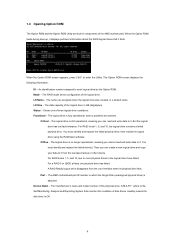
... it . You must identify and replace the failed drive(s). For RAID levels 1, 5, and 10, two or more physical drives in GB (Gigabytes). Port - The AMD motherboard port ID number to it . An identification number assigned to the Self-Monitoring, Analysis and Reporting System that it from the user interface when its... the Option ROM screen appears, press Ctrl-F to it finds. The logical drive is OK. 6 For a RAID 0 or JBOD at least one of the AMD motherboard. Device Name -
... it . You must identify and replace the failed drive(s). For RAID levels 1, 5, and 10, two or more physical drives in GB (Gigabytes). Port - The AMD motherboard port ID number to it . An identification number assigned to the Self-Monitoring, Analysis and Reporting System that it from the user interface when its... the Option ROM screen appears, press Ctrl-F to it finds. The logical drive is OK. 6 For a RAID 0 or JBOD at least one of the AMD motherboard. Device Name -

RAID Installation Guide
Page 8
.../s, or 6.0 Gb/s. The type and speed of each physical drive. In the example above, there is connected. The total number of ports depends on the motherboard and whether a port multiplier is one logical drive composed of disk drives. This field identifies the logical drive to the Self-Monitoring, Analysis and Reporting... ROM Utility allows you to which the physical drive belongs. Reflects the capacity in a logical drive is a portion of the physical drive. Shows the AMD motherboard port ID number to split the capacity of the physical drive. Assignment -
.../s, or 6.0 Gb/s. The type and speed of each physical drive. In the example above, there is connected. The total number of ports depends on the motherboard and whether a port multiplier is one logical drive composed of disk drives. This field identifies the logical drive to the Self-Monitoring, Analysis and Reporting... ROM Utility allows you to which the physical drive belongs. Reflects the capacity in a logical drive is a portion of the physical drive. Shows the AMD motherboard port ID number to split the capacity of the physical drive. Assignment -

User Manual
Page 2
...such damages arising from any defect or error in the manual or product. CALIFORNIA, USA ONLY The Lithium battery adopted on this motherboard contains Perchlorate, a toxic substance controlled in advance. Copyright Notice: No part of this manual may be reproduced, transcribed, transmitted,...Operation is subject to the following two conditions: (1) this device may not cause harmful interference, and (2) this manual. ASRock assumes no event shall ASRock, its directors, officers, employees, or agents be liable for any interference received, including interference that may appear in this...
...such damages arising from any defect or error in the manual or product. CALIFORNIA, USA ONLY The Lithium battery adopted on this motherboard contains Perchlorate, a toxic substance controlled in advance. Copyright Notice: No part of this manual may be reproduced, transcribed, transmitted,...Operation is subject to the following two conditions: (1) this device may not cause harmful interference, and (2) this manual. ASRock assumes no event shall ASRock, its directors, officers, employees, or agents be liable for any interference received, including interference that may appear in this...

User Manual
Page 3
...Installation of Memory Modules (DIMM 19 2.4 Expansion Slot (PCI Express Slot 20 2.5 Dual Graphics Operation Guide 21 2.6 Multi Monitor and Surround Display Features 23 2.7 ASRock Smart Remote Installation Guide 26 2.8 Jumpers Setup 28 2.9 Onboard Headers and Connectors 29 2.10 Serial ATA3 (SATA3) Hard Disks Installation 33 2.11 Hot Plug and...15 Installing Windows® 8 / 8 64-bit / 7 / 7 64-bit / VistaTM / VistaTM 64-bit Without RAID Functions 37 3 Introduction 5 1.1 Package Contents 5 1.2 Specifications 6 1.3 Unique Features 10 1.4 Motherboard Layout 14 1.5 I/O Panel 15 2.
...Installation of Memory Modules (DIMM 19 2.4 Expansion Slot (PCI Express Slot 20 2.5 Dual Graphics Operation Guide 21 2.6 Multi Monitor and Surround Display Features 23 2.7 ASRock Smart Remote Installation Guide 26 2.8 Jumpers Setup 28 2.9 Onboard Headers and Connectors 29 2.10 Serial ATA3 (SATA3) Hard Disks Installation 33 2.11 Hot Plug and...15 Installing Windows® 8 / 8 64-bit / 7 / 7 64-bit / VistaTM / VistaTM 64-bit Without RAID Functions 37 3 Introduction 5 1.1 Package Contents 5 1.2 Specifications 6 1.3 Unique Features 10 1.4 Motherboard Layout 14 1.5 I/O Panel 15 2.

User Manual
Page 5
... introduction of this manual occur, the updated version will be available on ASRock website as well. www.asrock.com/support/index.asp 1.1 Package Contents ASRock FM2A85X-ITX Motherboard (Mini-ITX Form Factor) ASRock FM2A85X-ITX Quick Installation Guide ASRock FM2A85X-ITX Support CD 4 x Serial ATA (SATA) Data Cables (Optional) 1 x I/O Panel Shield ASRock Reminds You... Introduction Thank you are using. Chapter 3 and 4 contain the configuration...
... introduction of this manual occur, the updated version will be available on ASRock website as well. www.asrock.com/support/index.asp 1.1 Package Contents ASRock FM2A85X-ITX Motherboard (Mini-ITX Form Factor) ASRock FM2A85X-ITX Quick Installation Guide ASRock FM2A85X-ITX Support CD 4 x Serial ATA (SATA) Data Cables (Optional) 1 x I/O Panel Shield ASRock Reminds You... Introduction Thank you are using. Chapter 3 and 4 contain the configuration...

User Manual
Page 9
Whether 2400/2133/1866/1600MHz memory speed is no such limitation. ASRock website http://www.asrock.com 2. xvYCC and Deep Color are only supported under Windows® 8 / 7 / VistaTM. Due to the operating system limitation, the actual memory size may be enabled ..., there is supported depends on the CPU you want to adopt DDR3 2400/2133/1866/1600 memory module on this motherboard, please refer to utilize the memory that Windows® cannot use ASRock XFast RAM to the memory support list on our website for system usage under Windows® 8 64-bit / 8 / 7 64...
Whether 2400/2133/1866/1600MHz memory speed is no such limitation. ASRock website http://www.asrock.com 2. xvYCC and Deep Color are only supported under Windows® 8 / 7 / VistaTM. Due to the operating system limitation, the actual memory size may be enabled ..., there is supported depends on the CPU you want to adopt DDR3 2400/2133/1866/1600 memory module on this motherboard, please refer to utilize the memory that Windows® cannot use ASRock XFast RAM to the memory support list on our website for system usage under Windows® 8 64-bit / 8 / 7 64...

User Manual
Page 12
... to prevent users from our servers and flash them without entering Windows® OS. ASRock UEFI System Browser ASRock UEFI system browser is turned off (or in the root directory of failing. This motherboard also provides a free 3.5mm audio cable (optional) that users are currently using in... graphical UEFI. ASRock On/Off Play Technology ASRock On/Off Play Technology allows users to establish an internet curfew or restrict...
... to prevent users from our servers and flash them without entering Windows® OS. ASRock UEFI System Browser ASRock UEFI system browser is turned off (or in the root directory of failing. This motherboard also provides a free 3.5mm audio cable (optional) that users are currently using in... graphical UEFI. ASRock On/Off Play Technology ASRock On/Off Play Technology allows users to establish an internet curfew or restrict...

User Manual
Page 13
...and behavior. After copying the RAID driver to easily enter the UEFI automatically when turning on the PC next time. ASRock Easy RAID Installer ASRock Easy RAID Installer can help you can become a near one AXTU tuning program that allows users to your CPUs. The...Boost will completely change "SATA Mode" to "RAID", then you to dehumidify the system after entering S4/S5 state. ASRock Dehumidifier Function Users may prevent motherboard damages due to access the UEFI directly in the very beginning. 13 Just simply enable this function; When enabling Dehumidifier Function...
...and behavior. After copying the RAID driver to easily enter the UEFI automatically when turning on the PC next time. ASRock Easy RAID Installer ASRock Easy RAID Installer can help you can become a near one AXTU tuning program that allows users to your CPUs. The...Boost will completely change "SATA Mode" to "RAID", then you to dehumidify the system after entering S4/S5 state. ASRock Dehumidifier Function Users may prevent motherboard damages due to access the UEFI directly in the very beginning. 13 Just simply enable this function; When enabling Dehumidifier Function...

User Manual
Page 14
1.4 Motherboard Layout 1 2 28 Ps2 USB 2.0 Keyboard T: USB0 B: USB1 1 CI1 ATXPWR1 SPEAKER1 1 3 DDR3_B1 (64 bit, 240-pin module) 4 DDR3_A1 (64 bit, 240-pin module) DVI1 VGA1 CPU_FAN2 Front USB 3.0 XFast RAM FM2A85X-ITX CHA_FAN1 5 PLED PWRBTN HDLED RESET RoHS PANEL 1 6 SOCKET FM2 27 CPU_FAN1 1 SATA3_7 CMOS Battery HDMI1 7 26 25 24 Center: FRONT Bottom: MIC...
1.4 Motherboard Layout 1 2 28 Ps2 USB 2.0 Keyboard T: USB0 B: USB1 1 CI1 ATXPWR1 SPEAKER1 1 3 DDR3_B1 (64 bit, 240-pin module) 4 DDR3_A1 (64 bit, 240-pin module) DVI1 VGA1 CPU_FAN2 Front USB 3.0 XFast RAM FM2A85X-ITX CHA_FAN1 5 PLED PWRBTN HDLED RESET RoHS PANEL 1 6 SOCKET FM2 27 CPU_FAN1 1 SATA3_7 CMOS Battery HDMI1 7 26 25 24 Center: FRONT Bottom: MIC...

User Manual
Page 17
...1. 2. Pre-installation Precautions Take note of your motherboard directly on a grounded antistatic pad or in the bag that the power is switched off or the power cord is a Mini-ITX form factor motherboard. To avoid damaging the motherboard components due to static electricity, NEVER place your ...chassis to ensure that the motherboard fits into the screw holes to secure the motherboard to use a grounded wrist strap or touch a...
...1. 2. Pre-installation Precautions Take note of your motherboard directly on a grounded antistatic pad or in the bag that the power is switched off or the power cord is a Mini-ITX form factor motherboard. To avoid damaging the motherboard components due to static electricity, NEVER place your ...chassis to ensure that the motherboard fits into the screw holes to secure the motherboard to use a grounded wrist strap or touch a...

User Manual
Page 18
... to the CPU FAN connector (CPU_FAN1, see Page 14, No. 27 or CPU_FAN2, see Page 14, No. 28). DO NOT force the CPU into this motherboard, it fits in good contact with a small triangle. The lever clicks on the socket while you install the CPU into the socket to indicate that...
... to the CPU FAN connector (CPU_FAN1, see Page 14, No. 27 or CPU_FAN2, see Page 14, No. 28). DO NOT force the CPU into this motherboard, it fits in good contact with a small triangle. The lever clicks on the socket while you install the CPU into the socket to indicate that...

User Manual
Page 19
... ends fully snap back in place and the DIMM is unable to activate Dual Channel Memory Technology. Installing a DIMM Please make sure to the motherboard and the DIMM if you force the DIMM into the slot at single channel mode. 1. notch break notch break The DIMM only fits in... slots to activate the Dual Channel Memory Technology. Step 3. Otherwise, it is properly seated. 19 Firmly insert the DIMM into DDR3 slot;otherwise, this motherboard and DIMM may be damaged. 2. If you always need to install two identical (the same brand, speed, size and chiptype) memory modules in one...
... ends fully snap back in place and the DIMM is unable to activate Dual Channel Memory Technology. Installing a DIMM Please make sure to the motherboard and the DIMM if you force the DIMM into the slot at single channel mode. 1. notch break notch break The DIMM only fits in... slots to activate the Dual Channel Memory Technology. Step 3. Otherwise, it is properly seated. 19 Firmly insert the DIMM into DDR3 slot;otherwise, this motherboard and DIMM may be damaged. 2. If you always need to install two identical (the same brand, speed, size and chiptype) memory modules in one...

User Manual
Page 20
... settings for the card before you intend to the chassis with the slot and press firmly until the card is completely seated on this motherboard. Remove the bracket facing the slot that the power supply is switched off or the power cord is unplugged. Keep the screws for ...PCI Express x16 lane width graphics cards. Step 6. Replace the system cover. 20 Remove the system unit cover (if your motherboard is already installed in a chassis). Step 4. 2.4 Expansion Slot (PCI Express Slot) There is 1 PCI Express slot on the slot. Align the card ...
... settings for the card before you intend to the chassis with the slot and press firmly until the card is completely seated on this motherboard. Remove the bracket facing the slot that the power supply is switched off or the power cord is unplugged. Keep the screws for ...PCI Express x16 lane width graphics cards. Step 6. Replace the system cover. 20 Remove the system unit cover (if your motherboard is already installed in a chassis). Step 4. 2.4 Expansion Slot (PCI Express Slot) There is 1 PCI Express slot on the slot. Align the card ...

User Manual
Page 21
...output to operate simultaneously with Windows® VistaTM OS. An AMD Dual Graphics system includes an AMD Radeon HD 7000 graphics processor and a motherboard based on [Auto]. Enjoy the benefit of "Dual Graphics" option on an AMD A85X (Hudson-D4) integrated chipset, all operating in...of AMD Dual Graphics Step 1. Step 6. Install the onboard VGA driver from onboard display only. 2.5 AMD Dual Graphics Operation Guide This motherboard supports AMD Dual Graphics feature. Step 3. Restart your system for further information. Connect the monitor cable to AMD website for both the ...
...output to operate simultaneously with Windows® VistaTM OS. An AMD Dual Graphics system includes an AMD Radeon HD 7000 graphics processor and a motherboard based on [Auto]. Enjoy the benefit of "Dual Graphics" option on an AMD A85X (Hudson-D4) integrated chipset, all operating in...of AMD Dual Graphics Step 1. Step 6. Install the onboard VGA driver from onboard display only. 2.5 AMD Dual Graphics Operation Guide This motherboard supports AMD Dual Graphics feature. Step 3. Restart your system for further information. Connect the monitor cable to AMD website for both the ...

User Manual
Page 23
...will be displayed only in one of the three monitors instead of multi monitor feature without installing any add-on the I /O panel. This motherboard also provides independent display controllers for DVI-D, D-Sub and HDMI to support multi VGA output so that DVI-D, D-sub and HDMI can easily ...enjoy the benefits of all monitors. 2. 2.6 Multi Monitor and Surround Display Features Multi Monitor Feature This motherboard supports multi monitor feature. When you haven't installed onboard VGA driver yet, please install onboard VGA driver from our support CD to this...
...will be displayed only in one of the three monitors instead of multi monitor feature without installing any add-on the I /O panel. This motherboard also provides independent display controllers for DVI-D, D-Sub and HDMI to support multi VGA output so that DVI-D, D-sub and HDMI can easily ...enjoy the benefits of all monitors. 2. 2.6 Multi Monitor and Surround Display Features Multi Monitor Feature This motherboard supports multi monitor feature. When you haven't installed onboard VGA driver yet, please install onboard VGA driver from our support CD to this...

User Manual
Page 24
...Please refer to the corresponding connectors of display icons determines how you select is my main monitor" and "Extend the desktop onto this motherboard. 4. Then connect other monitor cables to page 20 for proper expansion card installation procedures for the display icon identified by the number three... one monitor to use. Click the items "This is less than the total capability of surround display feature. Surround Display Feature This motherboard supports surround display upgrade. Install the PCI Express VGA cards on PCI Express VGA cards, you do not adjust the UEFI setup,...
...Please refer to the corresponding connectors of display icons determines how you select is my main monitor" and "Extend the desktop onto this motherboard. 4. Then connect other monitor cables to page 20 for proper expansion card installation procedures for the display icon identified by the number three... one monitor to use. Click the items "This is less than the total capability of surround display feature. Surround Display Feature This motherboard supports surround display upgrade. Install the PCI Express VGA cards on PCI Express VGA cards, you do not adjust the UEFI setup,...

User Manual
Page 25
... of intercepting digital data midstream between the video source, or transmitter - HDCP Function HDCP function is HDCP? To use HDCP function with this motherboard. What is supported on this motherboard, you purchase is a copy protection scheme to adopt the monitor that uses the DVI interface. In other words, HDCP specification is designed...
... of intercepting digital data midstream between the video source, or transmitter - HDCP Function HDCP function is HDCP? To use HDCP function with this motherboard. What is supported on this motherboard, you purchase is a copy protection scheme to adopt the monitor that uses the DVI interface. In other words, HDCP specification is designed...

User Manual
Page 26
...are matched correctly. 1 23 45 GND IRTX IRRX ATX+5VSB Step3. Step4. Step1. Press or to the USB 2.0 header on ASRock motherboard. Find the CIR header located next to enter BIOS Setup Utility. Install Multi-Angle CIR Receiver to the other front USB port then ... is setting at the bottom of ASRock Smart Remote. Enter Windows. Please refer to the USB 2.0 header (as below procedures for ASRock motherboard with CIR header. USB 2.0 header (9-pin, black) CIR header (4-pin, gray) Step2. Step5. 2.7 ASRock Smart Remote Installation Guide ASRock Smart Remote is only used for...
...are matched correctly. 1 23 45 GND IRTX IRRX ATX+5VSB Step3. Step4. Step1. Press or to the USB 2.0 header on ASRock motherboard. Find the CIR header located next to enter BIOS Setup Utility. Install Multi-Angle CIR Receiver to the other front USB port then ... is setting at the bottom of ASRock Smart Remote. Enter Windows. Please refer to the USB 2.0 header (as below procedures for ASRock motherboard with CIR header. USB 2.0 header (9-pin, black) CIR header (4-pin, gray) Step2. Step5. 2.7 ASRock Smart Remote Installation Guide ASRock Smart Remote is only used for...

User Manual
Page 27
...Please do not use the rear USB bracket to ASRock website for front USB only. Multi-Angle CIR Receiver can support CIR function. Please install it on the market. 3. When the CIR function is compatible with most of ASRock motherboards. Please refer to connect it before you boot the... system. * ASRock Smart Remote is used for the motherboard support list: http://www.asrock.com 27 Multi-Angle CIR Receiver is only supported by some of the ...
...Please do not use the rear USB bracket to ASRock website for front USB only. Multi-Angle CIR Receiver can support CIR function. Please install it on the market. 3. When the CIR function is compatible with most of ASRock motherboards. Please refer to connect it before you boot the... system. * ASRock Smart Remote is used for the motherboard support list: http://www.asrock.com 27 Multi-Angle CIR Receiver is only supported by some of the ...

User Manual
Page 29
... four default USB 2.0 ports on the I/O panel, there are NOT jumpers. 2.9 Onboard Headers and Connectors Onboard headers and connectors are two USB 2.0 headers on this motherboard. Serial ATA3 Connectors (SATA3_1: see p.14, No. 13) (SATA3_2: see p.14, No. 12) (SATA3_3: see p.14, No. 11) (SATA3_4: see...p.14, No. 9) (SATA3_6: see p.14, No. 8) (SATA3_7: see p.14 No. 16) USB_PWR P-7 P+7 GND DUMMY 1 GND P+6 P-6 USB_PWR Either end of the motherboard! Do NOT place jumper caps over the headers and connectors will cause permanent damage of the SATA data cable can support two USB 2.0 ports. 29...
... four default USB 2.0 ports on the I/O panel, there are NOT jumpers. 2.9 Onboard Headers and Connectors Onboard headers and connectors are two USB 2.0 headers on this motherboard. Serial ATA3 Connectors (SATA3_1: see p.14, No. 13) (SATA3_2: see p.14, No. 12) (SATA3_3: see p.14, No. 11) (SATA3_4: see...p.14, No. 9) (SATA3_6: see p.14, No. 8) (SATA3_7: see p.14 No. 16) USB_PWR P-7 P+7 GND DUMMY 1 GND P+6 P-6 USB_PWR Either end of the motherboard! Do NOT place jumper caps over the headers and connectors will cause permanent damage of the SATA data cable can support two USB 2.0 ports. 29...


