
User Manual
Page 3
... Motherboard Layout 10 1.4 I/O Panel 11 2 Installation 13 2.1 Screw Holes 13 2.2 Pre-installation Precautions 13 2.3 Installation of Memory Modules (DIMM 14 2.4 Expansion Slot (PCI Express Slot 15 2.5 Dual Monitor Feature 16 2.6 Jumpers Setup 18 2.7 Onboard Headers and Connectors 19 2.8 Serial ATA3 (SATA3) Hard Disks Installation 22 2.9 Hot Plug and Hot Swap Functions for SATA3 HDDs .... 23 2.10 SATA / SATAII / SATA3 HDD Hot Plug Feature and Operation Guide 24 2.11 Driver Installation Guide 26 2.12 Installing Windows® 7 / 7 64-bit / VistaTM / VistaTM 64-bit / XP / XP 64-bit...
... Motherboard Layout 10 1.4 I/O Panel 11 2 Installation 13 2.1 Screw Holes 13 2.2 Pre-installation Precautions 13 2.3 Installation of Memory Modules (DIMM 14 2.4 Expansion Slot (PCI Express Slot 15 2.5 Dual Monitor Feature 16 2.6 Jumpers Setup 18 2.7 Onboard Headers and Connectors 19 2.8 Serial ATA3 (SATA3) Hard Disks Installation 22 2.9 Hot Plug and Hot Swap Functions for SATA3 HDDs .... 23 2.10 SATA / SATAII / SATA3 HDD Hot Plug Feature and Operation Guide 24 2.11 Driver Installation Guide 26 2.12 Installing Windows® 7 / 7 64-bit / VistaTM / VistaTM 64-bit / XP / XP 64-bit...

User Manual
Page 7
... and SPEED LED) - ACPI 1.1 Compliance Wake Up Events - Drivers, Utilities, AntiVirus Software (Trial Version), ASRock Software Suite (CyberLink DVD Suite - OEM and Trial; ASRock APP Charger (see CAUTION 4) - ASRock Instant Flash (see CAUTION 6) - CPU Temperature Sensing - CPU/Chassis Fan Tachometer - Trial) - Instant Boot - ASRock AIWI (see CAUTION 9) - ASRock U-COP (see CAUTION 5) - CPU/Chassis Quiet Fan (Allow Chassis Fan Speed Auto-Adjust by CPU or MB Temperature) - CPU/Chassis Fan Multi-Speed Control - Front panel audio connector - 2 x USB 2.0 headers (support 4 USB...
... and SPEED LED) - ACPI 1.1 Compliance Wake Up Events - Drivers, Utilities, AntiVirus Software (Trial Version), ASRock Software Suite (CyberLink DVD Suite - OEM and Trial; ASRock APP Charger (see CAUTION 4) - ASRock Instant Flash (see CAUTION 6) - CPU Temperature Sensing - CPU/Chassis Fan Tachometer - Trial) - Instant Boot - ASRock AIWI (see CAUTION 9) - ASRock U-COP (see CAUTION 5) - CPU/Chassis Quiet Fan (Allow Chassis Fan Speed Auto-Adjust by CPU or MB Temperature) - CPU/Chassis Fan Multi-Speed Control - Front panel audio connector - 2 x USB 2.0 headers (support 4 USB...

User Manual
Page 8
... intuitive motion controlled games is no longer only available at your own risk and expense. Connecting 8 CAUTION! 1. For audio output, this utility, you can press key during the POST or press key to BIOS setup menu to access ASRock Instant Flash. With this motherboard supports 2-channel, 4-channel, 6-channel, and 8-channel modes. Overclocking may be less than 4GB for the reservation for proper connection. 4. For Windows® OS with overclocking, including adjusting the setting in Flash ROM. Please...
... intuitive motion controlled games is no longer only available at your own risk and expense. Connecting 8 CAUTION! 1. For audio output, this utility, you can press key during the POST or press key to BIOS setup menu to access ASRock Instant Flash. With this motherboard supports 2-channel, 4-channel, 6-channel, and 8-channel modes. Overclocking may be less than 4GB for the reservation for proper connection. 4. For Windows® OS with overclocking, including adjusting the setting in Flash ROM. Please...
User Manual
Page 10
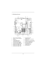
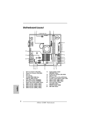
... CPU Fan 4 CPU Heatsink 5 2 x 240-pin DDR3 DIMM Slots (DDR3_A1, DDR3_A2, Blue) 6 Clear CMOS Jumper (CLRCMOS1) 7 ATX Power Connector (ATXPWR1) 8 System Panel Header (PANEL1, White) 9 SATA3 Connector (SATA3_4, White) 10 SATA3 Connector (SATA3_2, White) 11 SATA3 Connector (SATA3_3, White) 12 SATA3 Connector (SATA3_1, White) 13 Chassis Speaker Header (SPEAKER 1, White) 14 Chassis Fan Connector (CHA_FAN2) 15 32Mb SPI Flash 16 PCI Express 2.0 x16 Slot (PCIE1, Blue) 17 Consumer Infrared Module Header (CIR1) 18 USB 2.0 Header (USB8_9, Blue) 19 USB 2.0 Header (USB6_7, Blue) 20 Front Panel Audio Header...
... CPU Fan 4 CPU Heatsink 5 2 x 240-pin DDR3 DIMM Slots (DDR3_A1, DDR3_A2, Blue) 6 Clear CMOS Jumper (CLRCMOS1) 7 ATX Power Connector (ATXPWR1) 8 System Panel Header (PANEL1, White) 9 SATA3 Connector (SATA3_4, White) 10 SATA3 Connector (SATA3_2, White) 11 SATA3 Connector (SATA3_3, White) 12 SATA3 Connector (SATA3_1, White) 13 Chassis Speaker Header (SPEAKER 1, White) 14 Chassis Fan Connector (CHA_FAN2) 15 32Mb SPI Flash 16 PCI Express 2.0 x16 Slot (PCIE1, Blue) 17 Consumer Infrared Module Header (CIR1) 18 USB 2.0 Header (USB8_9, Blue) 19 USB 2.0 Header (USB6_7, Blue) 20 Front Panel Audio Header...
User Manual
Page 16
...fits of dual monitor feature without installing any add-on the I/O panel. If you have installed onboard VGA driver from our support CD to your system already, you haven't installed onboard VGA driver yet, please install onboard VGA driver from our support CD to this motherboard. This motherboard also provides independent display controllers for DVI-D, D-Sub and HDMI to HDMI port on VGA card to your system and restart your system boots. You can drive same or different...
...fits of dual monitor feature without installing any add-on the I/O panel. If you have installed onboard VGA driver from our support CD to your system already, you haven't installed onboard VGA driver yet, please install onboard VGA driver from our support CD to this motherboard. This motherboard also provides independent display controllers for DVI-D, D-Sub and HDMI to HDMI port on VGA card to your system and restart your system boots. You can drive same or different...

User Manual
Page 21
... to the fan connectors and match the black wire to the ground pin. The front panel design may differ by fan power voltage. CHA_FAN2 supports fan speed control by chassis. When connecting your power supply along with Pin 1 and Pin 13. Chassis Fan Connectors (4-pin CHA_FAN1) (see p.10 No. 2) CHA_FAN_SPEED +12V GND FAN_SPEED_CONTROL (3-pin CHA_FAN2) (see p.10 No. 21) 20-Pin ATX Power Supply Installation 1 13 This COM1 header supports a serial port module. 21 A front panel module mainly consists of power switch, reset switch, power LED, hard drive activity LED, speaker and...
... to the fan connectors and match the black wire to the ground pin. The front panel design may differ by fan power voltage. CHA_FAN2 supports fan speed control by chassis. When connecting your power supply along with Pin 1 and Pin 13. Chassis Fan Connectors (4-pin CHA_FAN1) (see p.10 No. 2) CHA_FAN_SPEED +12V GND FAN_SPEED_CONTROL (3-pin CHA_FAN2) (see p.10 No. 21) 20-Pin ATX Power Supply Installation 1 13 This COM1 header supports a serial port module. 21 A front panel module mainly consists of power switch, reset switch, power LED, hard drive activity LED, speaker and...
User Manual
Page 26
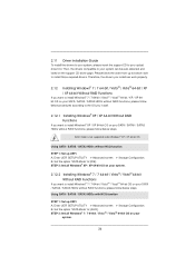
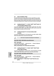
... be auto-detected and listed on your optical drive first. Set the option "SATA Mode" to install those required drivers. Please follow below steps. AHCI mode is not supported under Windows® XP / XP 64-bit OS. Set the option "SATA Mode" to your SATA / SATAII / SATA3 HDDs without RAID functions, please follow the order from up to bottom side to [AHCI]. Using SATA / SATAII / SATA3 HDDs without NCQ function STEP 1: Set up UEFI. Enter UEFI SETUP UTILITY Advanced screen Storage Con...
... be auto-detected and listed on your optical drive first. Set the option "SATA Mode" to install those required drivers. Please follow below steps. AHCI mode is not supported under Windows® XP / XP 64-bit OS. Set the option "SATA Mode" to your SATA / SATAII / SATA3 HDDs without RAID functions, please follow the order from up to bottom side to [AHCI]. Using SATA / SATAII / SATA3 HDDs without NCQ function STEP 1: Set up UEFI. Enter UEFI SETUP UTILITY Advanced screen Storage Con...

User Manual
Page 28
... OC Tweaker To set up overclocking features Advanced To set up the advanced UEFI features H/W Monitor To display current hardware status Boot To set up the default system device to locate and load the Operating System Security To set up the computer. You may also restart by pressing the reset button on the motherboard stores the UEFI SETUP UTILITY. Chapter 3: UEFI SETUP UTILITY 3.1 Introduction This section explains how to use the mouse to...
... OC Tweaker To set up overclocking features Advanced To set up the advanced UEFI features H/W Monitor To display current hardware status Boot To set up the default system device to locate and load the Operating System Security To set up the computer. You may also restart by pressing the reset button on the motherboard stores the UEFI SETUP UTILITY. Chapter 3: UEFI SETUP UTILITY 3.1 Introduction This section explains how to use the mouse to...

User Manual
Page 36
...enable or disable SATA controller. 3.4.4 Storage Configuration SATA Controller Use this item to enable or disable the S.M.A.R.T. (Self-Monitoring, Analysis, and Reporting Technology) feature. SATA IDE Combined Mode This option is [IDE Mode]. Hard Disk S.M.A.R.T. The default value is [Enabled]. Configuration options: [Disabled] and [Enabled]. 36 AHCI (Advanced Host Controller Interface) supports NCQ and other new features that will improve SATA disk performance but IDE mode does not have these advantages. Use this to enable or disable SATA IDE Combined Mode. SATA Mode Use...
...enable or disable SATA controller. 3.4.4 Storage Configuration SATA Controller Use this item to enable or disable the S.M.A.R.T. (Self-Monitoring, Analysis, and Reporting Technology) feature. SATA IDE Combined Mode This option is [IDE Mode]. Hard Disk S.M.A.R.T. The default value is [Enabled]. Configuration options: [Disabled] and [Enabled]. 36 AHCI (Advanced Host Controller Interface) supports NCQ and other new features that will improve SATA disk performance but IDE mode does not have these advantages. Use this to enable or disable SATA IDE Combined Mode. SATA Mode Use...

User Manual
Page 39
...[Auto] - Enables legacy support if USB devices are four configuration options: [Enabled], [Auto], [Disabled] and [UEFI Setup Only]. USB devices are not allowed to enable or disable the use of these four options: [Enabled] - The default value is recommended to select [Disabled] to use only under legacy OS and UEFI setup when [Disabled] is selected. Enables support for USB devices. If you have USB compatibility issue, it is [Enabled]. There are connected. [Disabled] - USB devices are allowed to enter OS. [UEFI Setup Only] - 3.4.7 USB Configuration USB 2.0 Controller...
...[Auto] - Enables legacy support if USB devices are four configuration options: [Enabled], [Auto], [Disabled] and [UEFI Setup Only]. USB devices are not allowed to enable or disable the use of these four options: [Enabled] - The default value is recommended to select [Disabled] to use only under legacy OS and UEFI setup when [Disabled] is selected. Enables support for USB devices. If you have USB compatibility issue, it is [Enabled]. There are connected. [Disabled] - USB devices are allowed to enter OS. [UEFI Setup Only] - 3.4.7 USB Configuration USB 2.0 Controller...
User Manual
Page 44
Chapter 4: Software Support 4.1 Install Operating System This motherboard supports various Microsoft® Windows® operating systems: 7 / 7 64-bit / VistaTM / VistaTM 64-bit / XP / XP Media Center / XP 64-bit. Because motherboard settings and hardware options vary, use the setup procedures in the Support CD to your CD-ROM drive. Please install the necessary drivers to visit ASRock's website at http://www.asrock.com; If the Main Menu did not appear automatically, locate and double click...
Chapter 4: Software Support 4.1 Install Operating System This motherboard supports various Microsoft® Windows® operating systems: 7 / 7 64-bit / VistaTM / VistaTM 64-bit / XP / XP Media Center / XP 64-bit. Because motherboard settings and hardware options vary, use the setup procedures in the Support CD to your CD-ROM drive. Please install the necessary drivers to visit ASRock's website at http://www.asrock.com; If the Main Menu did not appear automatically, locate and double click...
Quick Installation Guide
Page 2
... CPU Fan 4 CPU Heatsink 5 2 x 240-pin DDR3 DIMM Slots (DDR3_A1, DDR3_A2, Blue) 6 Clear CMOS Jumper (CLRCMOS1) 7 ATX Power Connector (ATXPWR1) 8 System Panel Header (PANEL1, White) 9 SATA3 Connector (SATA3_4, White) 10 SATA3 Connector (SATA3_2, White) 11 SATA3 Connector (SATA3_3, White) 12 SATA3 Connector (SATA3_1, White) 13 Chassis Speaker Header (SPEAKER 1, White) 14 Chassis Fan Connector (CHA_FAN2) 15 32Mb SPI Flash 16 PCI Express 2.0 x16 Slot (PCIE1, Blue) 17 Consumer Infrared Module Header (CIR1) 18 USB 2.0 Header (USB8_9, Blue) 19 USB 2.0 Header (USB6_7, Blue) 20 Front Panel Audio Header...
... CPU Fan 4 CPU Heatsink 5 2 x 240-pin DDR3 DIMM Slots (DDR3_A1, DDR3_A2, Blue) 6 Clear CMOS Jumper (CLRCMOS1) 7 ATX Power Connector (ATXPWR1) 8 System Panel Header (PANEL1, White) 9 SATA3 Connector (SATA3_4, White) 10 SATA3 Connector (SATA3_2, White) 11 SATA3 Connector (SATA3_3, White) 12 SATA3 Connector (SATA3_1, White) 13 Chassis Speaker Header (SPEAKER 1, White) 14 Chassis Fan Connector (CHA_FAN2) 15 32Mb SPI Flash 16 PCI Express 2.0 x16 Slot (PCIE1, Blue) 17 Consumer Infrared Module Header (CIR1) 18 USB 2.0 Header (USB8_9, Blue) 19 USB 2.0 Header (USB6_7, Blue) 20 Front Panel Audio Header...
Quick Installation Guide
Page 3
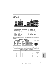
... 6 Rear Speaker (Black) 7 Optical SPDIF Out Port 8 Line In (Light Blue) ** 9 Front Speaker (Lime) 10 Microphone (Pink) 11 USB 2.0 Ports (USB45) 12 eSATA3 Port 13 VGA/HDMI Port 14 VGA/DVI-D Port 15 USB 2.0 Ports (USB01) * There are two LED next to the table below for Audio Output Connection Audio Output Channels Front Speaker Rear Speaker Central / Bass Line In or (No. 9) (No. 6) (No. 5) Side Speaker (No. 8) 2 V -- -- -- 4 V V -- -- 6 V V V -- 8 V V V V English 3 ASRock E350M1 Motherboard LAN Port LED Indications Activity/Link LED SPEED LED Status Description...
... 6 Rear Speaker (Black) 7 Optical SPDIF Out Port 8 Line In (Light Blue) ** 9 Front Speaker (Lime) 10 Microphone (Pink) 11 USB 2.0 Ports (USB45) 12 eSATA3 Port 13 VGA/HDMI Port 14 VGA/DVI-D Port 15 USB 2.0 Ports (USB01) * There are two LED next to the table below for Audio Output Connection Audio Output Channels Front Speaker Rear Speaker Central / Bass Line In or (No. 9) (No. 6) (No. 5) Side Speaker (No. 8) 2 V -- -- -- 4 V V -- -- 6 V V V -- 8 V V V V English 3 ASRock E350M1 Motherboard LAN Port LED Indications Activity/Link LED SPEED LED Status Description...

Quick Installation Guide
Page 5
... Installation Guide ASRock E350M1 Support CD 2 x Serial ATA (SATA) Data Cables (Optional) 1 x I/O Panel Shield ASRock Reminds You... ASRock website http://www.asrock.com If you require technical support related to this manual occur, the updated version will be found in the user manual presented in Storage Configuration to change without further notice. It delivers excellent performance with robust design conforming to ASRock's commitment to set the BIOS option in the Support CD. Because the motherboard...
... Installation Guide ASRock E350M1 Support CD 2 x Serial ATA (SATA) Data Cables (Optional) 1 x I/O Panel Shield ASRock Reminds You... ASRock website http://www.asrock.com If you require technical support related to this manual occur, the updated version will be found in the user manual presented in Storage Configuration to change without further notice. It delivers excellent performance with robust design conforming to ASRock's commitment to set the BIOS option in the Support CD. Because the motherboard...
Quick Installation Guide
Page 7
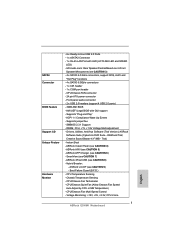
... USB 2.0 Ports - 1 x eSATA3 Connector - 1 x RJ-45 LAN Port with GUI support - AMI UEFI Legal BIOS with LED (ACT/LINK LED and SPEED LED) - Drivers, Utilities, AntiVirus Software (Trial Version), ASRock Software Suite (CyberLink DVD Suite - ASRock APP Charger (see CAUTION 4) - CPU/Chassis Fan Tachometer - CPU/Chassis Fan Multi-Speed Control - ACPI 1.1 Compliance Wake Up Events - Instant Boot - Boot Failure Guard (B.F.G.) - CPU/Chassis Quiet Fan (Allow Chassis Fan Speed Auto-Adjust by CPU or MB Temperature) - Front panel audio connector - 2 x USB 2.0 headers (support 4 USB 2.0 ports...
... USB 2.0 Ports - 1 x eSATA3 Connector - 1 x RJ-45 LAN Port with GUI support - AMI UEFI Legal BIOS with LED (ACT/LINK LED and SPEED LED) - Drivers, Utilities, AntiVirus Software (Trial Version), ASRock Software Suite (CyberLink DVD Suite - ASRock APP Charger (see CAUTION 4) - CPU/Chassis Fan Tachometer - CPU/Chassis Fan Multi-Speed Control - ACPI 1.1 Compliance Wake Up Events - Instant Boot - Boot Failure Guard (B.F.G.) - CPU/Chassis Quiet Fan (Allow Chassis Fan Speed Auto-Adjust by CPU or MB Temperature) - Front panel audio connector - 2 x USB 2.0 headers (support 4 USB 2.0 ports...
Quick Installation Guide
Page 8
... POST or press key to BIOS setup menu to change. This convenient BIOS update tool allows you have to do is a BIOS flash utility embedded in the BIOS, applying Untied Overclocking Technology, or using the third-party overclocking tools. We are not responsible for system usage under Windows® 7 / VistaTM / XP. Please check AMD website for proper connection. 4. To experience intuitive motion controlled games is subject to access ASRock Instant Flash...
... POST or press key to BIOS setup menu to change. This convenient BIOS update tool allows you have to do is a BIOS flash utility embedded in the BIOS, applying Untied Overclocking Technology, or using the third-party overclocking tools. We are not responsible for system usage under Windows® 7 / VistaTM / XP. Please check AMD website for proper connection. 4. To experience intuitive motion controlled games is subject to access ASRock Instant Flash...
Quick Installation Guide
Page 14
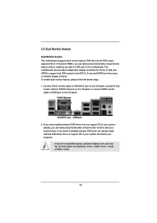
You can freely enjoy the benefits of dual monitor function after your computer. D-Sub, DVI-D and HDMI monitors cannot be enabled at the same time. 2. If you can only choose the combination: DVI-D + HDMI, DVI-D + D-Sub, or HDMI + D-Sub. 14 ASRock E350M1 Motherboard English If you haven't installed onboard VGA driver yet, please install onboard VGA driver from our support CD to your system already, you have installed onboard VGA driver from our support CD to your system and restart your system boots.
You can freely enjoy the benefits of dual monitor function after your computer. D-Sub, DVI-D and HDMI monitors cannot be enabled at the same time. 2. If you can only choose the combination: DVI-D + HDMI, DVI-D + D-Sub, or HDMI + D-Sub. 14 ASRock E350M1 Motherboard English If you haven't installed onboard VGA driver yet, please install onboard VGA driver from our support CD to your system already, you have installed onboard VGA driver from our support CD to your system and restart your system boots.

Quick Installation Guide
Page 19
...English 19 ASRock E350M1 Motherboard CHA_FAN2 supports fan speed control by chassis. A front panel module mainly consists of power switch, reset switch, power LED, hard drive activity LED, speaker and etc. Chassis Speaker Header (4-pin SPEAKER 1) (see p.2 No. 21) 20-Pin ATX Power Supply Installation 1 13 This COM1 header supports a serial port module. CPU_FAN1 supports fan speed control. To use the 20-pin ATX power supply, please plug your chassis front panel module to this connector. 1 13 Though this header. The front panel design may differ by fan power voltage.
...English 19 ASRock E350M1 Motherboard CHA_FAN2 supports fan speed control by chassis. A front panel module mainly consists of power switch, reset switch, power LED, hard drive activity LED, speaker and etc. Chassis Speaker Header (4-pin SPEAKER 1) (see p.2 No. 21) 20-Pin ATX Power Supply Installation 1 13 This COM1 header supports a serial port module. CPU_FAN1 supports fan speed control. To use the 20-pin ATX power supply, please plug your chassis front panel module to this connector. 1 13 Though this header. The front panel design may differ by fan power voltage.
Quick Installation Guide
Page 20
.... A. B. 2.8 Driver Installation Guide To install the drivers to your system, please insert the support CD to install Windows® XP / XP 64-bit OS on your SATA / SATAII / SATA3 HDDs without RAID functions, please follow below steps. Then, the drivers compatible to install those required drivers. Please follow the order from up to bottom side to your system. 20 ASRock E350M1 Motherboard English Enter UEFI SETUP UTILITY Advanced screen Storage Configuration. Set the option "SATA Mode" to [IDE].
.... A. B. 2.8 Driver Installation Guide To install the drivers to your system, please insert the support CD to install Windows® XP / XP 64-bit OS on your SATA / SATAII / SATA3 HDDs without RAID functions, please follow below steps. Then, the drivers compatible to install those required drivers. Please follow the order from up to bottom side to your system. 20 ASRock E350M1 Motherboard English Enter UEFI SETUP UTILITY Advanced screen Storage Configuration. Set the option "SATA Mode" to [IDE].

Quick Installation Guide
Page 22
... BIOS Setup, please refer to the User Manual (PDF file) contained in the Support CD to enter BIOS Setup after POST, please restart the system by pressing + + , or pressing the reset button on the system chassis. It is a menu-driven program, which allows you wish to display the menus. 22 ASRock E350M1 Motherboard English The Support CD that will display the Main Menu automatically if "AUTORUN" is designed to enter BIOS Setup utility; When you start...
... BIOS Setup, please refer to the User Manual (PDF file) contained in the Support CD to enter BIOS Setup after POST, please restart the system by pressing + + , or pressing the reset button on the system chassis. It is a menu-driven program, which allows you wish to display the menus. 22 ASRock E350M1 Motherboard English The Support CD that will display the Main Menu automatically if "AUTORUN" is designed to enter BIOS Setup utility; When you start...


