
User Manual
Page 3
... of Heatsink and CPU fan 15 2.5 Installation of Memory Modules (DIMM 16 2.6 Expansion Slots (PCI, HDMR, and PCI Express Slots) ....... 18 2.7 DVI Graphics-HDCP Card Installation Guide 19 2.8 Jumpers Setup 21 2.9 Onboard Headers and Connectors 22 2.10 SATAII Hard Disk Setup Guide 26 2.11 Serial ATA (SATA) / Serial ATAII (SATAII) Hard Disks Installation 27 2.12 Driver Installation Guide 27 2.13 HDMR Card and Driver Installation 27 2.14 Untied Overclocking Technology 27 3 BIOS SETUP UTILITY 28 3.1 Introduction 28 3.1.1 BIOS Menu Bar 28 3.1.2 Navigation Keys 29 3.2 Main Screen 29...
... of Heatsink and CPU fan 15 2.5 Installation of Memory Modules (DIMM 16 2.6 Expansion Slots (PCI, HDMR, and PCI Express Slots) ....... 18 2.7 DVI Graphics-HDCP Card Installation Guide 19 2.8 Jumpers Setup 21 2.9 Onboard Headers and Connectors 22 2.10 SATAII Hard Disk Setup Guide 26 2.11 Serial ATA (SATA) / Serial ATAII (SATAII) Hard Disks Installation 27 2.12 Driver Installation Guide 27 2.13 HDMR Card and Driver Installation 27 2.14 Untied Overclocking Technology 27 3 BIOS SETUP UTILITY 28 3.1 Introduction 28 3.1.1 BIOS Menu Bar 28 3.1.2 Navigation Keys 29 3.2 Main Screen 29...

User Manual
Page 8
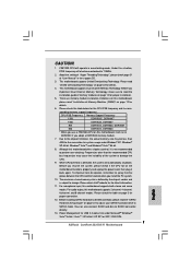
... this motherboard supports both stereo and mono modes. About the setting of memory modules on page 27 for details. 6. Before you adopt a DDRII533 memory module. 7. For microphone input, this situation, PCIE frequency will run at DDRII500 if you implement Dual Channel Memory Technology, make sure to perform over-clocking. Please read the "SATAII Hard Disk Setup Guide" on this motherboard, it will also be less than the recommended CPU bus frequencies...
... this motherboard supports both stereo and mono modes. About the setting of memory modules on page 27 for details. 6. Before you adopt a DDRII533 memory module. 7. For microphone input, this situation, PCIE frequency will run at DDRII500 if you implement Dual Channel Memory Technology, make sure to perform over-clocking. Please read the "SATAII Hard Disk Setup Guide" on this motherboard, it will also be less than the recommended CPU bus frequencies...

User Manual
Page 10
...17 Chassis Fan Connector (CHA_FAN1) 4 775-Pin CPU Socket 18 USB 2.0 Header (USB6_7, Blue) 5 North Bridge Controller 19 USB 2.0 Header (USB4_5, Blue) 6 Clear CMOS Jumper (CLRCMOS1) 20 Floppy Connector (FLOPPY1) 7 2 x 240-pin DDRII DIMM Slots 21 HDMR Slot (HDMR1) (Dual Channel A: DDRII_1, DDRII_3; Orange) 24 Internal Audio Connector: CD1 (Black) 9 South Bridge Controller 25 PCI Express x1 Slot (PCIE2) 10 IDE1 Connector (IDE1, Blue) 26 PCI Express x16 Slot (PCIE1) 11 Chassis Speaker Header (SPEAKER 1) 27 ATX Power Connector (ATXPWR1) 12 System Panel Header (PANEL1) 28 BIOS...
...17 Chassis Fan Connector (CHA_FAN1) 4 775-Pin CPU Socket 18 USB 2.0 Header (USB6_7, Blue) 5 North Bridge Controller 19 USB 2.0 Header (USB4_5, Blue) 6 Clear CMOS Jumper (CLRCMOS1) 20 Floppy Connector (FLOPPY1) 7 2 x 240-pin DDRII DIMM Slots 21 HDMR Slot (HDMR1) (Dual Channel A: DDRII_1, DDRII_3; Orange) 24 Internal Audio Connector: CD1 (Black) 9 South Bridge Controller 25 PCI Express x1 Slot (PCIE2) 10 IDE1 Connector (IDE1, Blue) 26 PCI Express x16 Slot (PCIE1) 11 Chassis Speaker Header (SPEAKER 1) 27 ATX Power Connector (ATXPWR1) 12 System Panel Header (PANEL1) 28 BIOS...
User Manual
Page 20
... use HDCP function with DVI Graphics-HDCP card. HDCP Function with DVI Graphics-HDCP Card HDCP function is designed to the VGA/D-Sub port on the I/O panel of DVI-D output function with this motherboard is compatible. 20 such as a monitor, television or projector. such as a computer, DVD player or set -top-boxes, as well as it is being transmitted. In other words, HDCP specification is supported with this motherboard...
... use HDCP function with DVI Graphics-HDCP card. HDCP Function with DVI Graphics-HDCP Card HDCP function is designed to the VGA/D-Sub port on the I/O panel of DVI-D output function with this motherboard is compatible. 20 such as a monitor, television or projector. such as a computer, DVD player or set -top-boxes, as well as it is being transmitted. In other words, HDCP specification is supported with this motherboard...

User Manual
Page 23
... motherboard. This connector allows you use AC'97 audio panel, please install it to the front panel audio header as a CD-ROM, DVD-ROM, TV tuner card, or MPEG card. D. Connect Mic_IN (MIC) to function correctly. Enter Advanced Settings, and then select Chipset Configuration. If you to Ground (GND). You don't need to [Enabled]. 23 Set the Front Panel Control option from sound sources such as below: A. Please follow the instruction in our manual and chassis manual to OUT2_L. Enter BIOS Setup Utility. Connect...
... motherboard. This connector allows you use AC'97 audio panel, please install it to the front panel audio header as a CD-ROM, DVD-ROM, TV tuner card, or MPEG card. D. Connect Mic_IN (MIC) to function correctly. Enter Advanced Settings, and then select Chipset Configuration. If you to Ground (GND). You don't need to [Enabled]. 23 Set the Front Panel Control option from sound sources such as below: A. Please follow the instruction in our manual and chassis manual to OUT2_L. Enter BIOS Setup Utility. Connect...
User Manual
Page 27
... the support CD to install the SATA / SATAII hard disks. STEP 2: Connect the SATA power cable to fixed PCI / PCIE buses. Before you plan to use HDMR card function on this motherboard. You may install SATA / SATAII hard disks on this motherboard, and you finish installing all drivers to your system now, but PCI / PCIE buses are in the future, you enable Untied Overclocking function, please enter "Overclock Mode" option of the SATA data cable to the SATA / SATAII hard disk. 2.12 Driver Installation Guide To install the drivers...
... the support CD to install the SATA / SATAII hard disks. STEP 2: Connect the SATA power cable to fixed PCI / PCIE buses. Before you plan to use HDMR card function on this motherboard. You may install SATA / SATAII hard disks on this motherboard, and you finish installing all drivers to your system now, but PCI / PCIE buses are in the future, you enable Untied Overclocking function, please enter "Overclock Mode" option of the SATA data cable to the SATA / SATAII hard disk. 2.12 Driver Installation Guide To install the drivers...

User Manual
Page 29
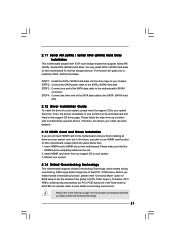
...:Minute:Second] Use this section, you enter the BIOS SETUP UTILITY, the Main screen will appear and display the system overview Main Advanced BIOS SETUP UTILITY H/W Monitor Boot System Overview System Time System Date [14:00:09] [Fri 04/13/2007] BIOS Version : ConRoe1333-DVI/H BIOS P1.20 Processor Type : Intel (R) CPU 3.40 GHz (64bit supported) Processor Speed : 3400 MHz Microcode Update : F34/17 Cache Size : 1024KB Total Memory DDRII1 DDRII2 DDRII3 DDRII4 : 512MB with 8MB shared memory Dual-Channel Memory Mode : 256MB...
...:Minute:Second] Use this section, you enter the BIOS SETUP UTILITY, the Main screen will appear and display the system overview Main Advanced BIOS SETUP UTILITY H/W Monitor Boot System Overview System Time System Date [14:00:09] [Fri 04/13/2007] BIOS Version : ConRoe1333-DVI/H BIOS P1.20 Processor Type : Intel (R) CPU 3.40 GHz (64bit supported) Processor Speed : 3400 MHz Microcode Update : F34/17 Cache Size : 1024KB Total Memory DDRII1 DDRII2 DDRII3 DDRII4 : 512MB with 8MB shared memory Dual-Channel Memory Mode : 256MB...

User Manual
Page 30
.... Boot Failure Guard Enable or disable the feature of Boot Failure Guard. The default value is [Auto]. CPU Configuration Chipset Configuration ACPI Configuration IDE Configuration PCIPnP Configuration Floppy Configuration SuperIO Configuration USB Configuration Configure CPU Select Screen Select Item Enter Go to malfunction. BIOS SETUP UTILITY Main Advanced H/W Monitor Boot Security Exit Advanced Settings WARNING : Setting wrong values in this option to malfunction. 3.3.1 CPU Configuration BIOS SETUP UTILITY Advanced CPU Configuration Overclock Mode CPU Frequency (MHz) PCIE...
.... Boot Failure Guard Enable or disable the feature of Boot Failure Guard. The default value is [Auto]. CPU Configuration Chipset Configuration ACPI Configuration IDE Configuration PCIPnP Configuration Floppy Configuration SuperIO Configuration USB Configuration Configure CPU Select Screen Select Item Enter Go to malfunction. BIOS SETUP UTILITY Main Advanced H/W Monitor Boot Security Exit Advanced Settings WARNING : Setting wrong values in this option to malfunction. 3.3.1 CPU Configuration BIOS SETUP UTILITY Advanced CPU Configuration Overclock Mode CPU Frequency (MHz) PCIE...

User Manual
Page 31
... You may select [Enabled] to enable P4 CPU internal thermal control mechanism to keep the CPU from the chipset. No-Excute Memory Protection No-Execution (NX) Memory Protection Technology is supported through the native processor instructions HLT and MWAIT and requires no hardware support from overheated. If the CPU you adopt supports EIST (Intel (R) SpeedStep(tm) tech.), and you plan to [Enabled] if using Microsoft® Windows® XP...
... You may select [Enabled] to enable P4 CPU internal thermal control mechanism to keep the CPU from the chipset. No-Excute Memory Protection No-Execution (NX) Memory Protection Technology is supported through the native processor instructions HLT and MWAIT and requires no hardware support from overheated. If the CPU you adopt supports EIST (Intel (R) SpeedStep(tm) tech.), and you plan to [Enabled] if using Microsoft® Windows® XP...

User Manual
Page 32
...)]. If you install Windows® XP and select [Auto], you will configure the following items by SPD [Enabled] DRAM CAS# Latency [Auto] Primary Graphics Adapter Internal Graphics Mode Select DVMT Mode Select DVMT/FIXED Memory [PCI] [Auto] [DVMT Mode] [Maximum DVMT] OnBoard HD Audio Front Panel CD-In OnBoard Lan [Auto] [Auto] [Enabled] [Enabled] PCI Fix Function VCCM Voltage [Enabled] [Auto] Options Auto 200MHz 266MHz 333MHz (DDRII400) (DDRII533) (DDRII667) +F1 F9 F10 ESC Select Screen Select Item Change Option General Help Load Defaults Save and Exit...
...)]. If you install Windows® XP and select [Auto], you will configure the following items by SPD [Enabled] DRAM CAS# Latency [Auto] Primary Graphics Adapter Internal Graphics Mode Select DVMT Mode Select DVMT/FIXED Memory [PCI] [Auto] [DVMT Mode] [Maximum DVMT] OnBoard HD Audio Front Panel CD-In OnBoard Lan [Auto] [Auto] [Enabled] [Enabled] PCI Fix Function VCCM Voltage [Enabled] [Auto] Options Auto 200MHz 266MHz 333MHz (DDRII400) (DDRII533) (DDRII667) +F1 F9 F10 ESC Select Screen Select Item Change Option General Help Load Defaults Save and Exit...

User Manual
Page 33
...Precharge This controls the number of memory accessing. The default value is issued. Configuration options: [2 DRAM Clocks], [3 DRAM Clocks], [4 DRAM Clocks], [5 DRAM Clocks], and [6 DRAM Clocks]. If you select [Enabled, 8MB] or [Enabled, 1MB], the onboard VGA will be automatically disabled when you install VGA card; In Fixed mode, a fixed-size fragment of the system memory is cooperatively using this amount to adjust the means of DRAM clocks for the motherboard through efficient memory utilization. DRAM RAS# to the graphics core. Internal Graphics Mode Select If...
...Precharge This controls the number of memory accessing. The default value is issued. Configuration options: [2 DRAM Clocks], [3 DRAM Clocks], [4 DRAM Clocks], [5 DRAM Clocks], and [6 DRAM Clocks]. If you select [Enabled, 8MB] or [Enabled, 1MB], the onboard VGA will be automatically disabled when you install VGA card; In Fixed mode, a fixed-size fragment of the system memory is cooperatively using this amount to adjust the means of DRAM clocks for the motherboard through efficient memory utilization. DRAM RAS# to the graphics core. Internal Graphics Mode Select If...

User Manual
Page 40
...Configuration options: [Disabled], [378], and [278]. EPP Version Use this item to set the EPP version. ECP Mode DMA Channel Use this item to set the operation mode of USB controller. USB 2.0 Support Use this item to enable or disable the USB 2.0 support. Configuration options: [IRQ5] and [IRQ7]. 3.3.8 USB Configuration BIOS SETUP UTILITY Advanced USB Configuration USB Controller USB 2.0 Support Legacy USB Support [Enabled] [Enabled] [Disabled] To enable or disable the onboard USB controllers. +F1 F9 F10 ESC Select Screen Select Item Change Option General Help Load Defaults...
...Configuration options: [Disabled], [378], and [278]. EPP Version Use this item to set the EPP version. ECP Mode DMA Channel Use this item to set the operation mode of USB controller. USB 2.0 Support Use this item to enable or disable the USB 2.0 support. Configuration options: [IRQ5] and [IRQ7]. 3.3.8 USB Configuration BIOS SETUP UTILITY Advanced USB Configuration USB Controller USB 2.0 Support Legacy USB Support [Enabled] [Enabled] [Disabled] To enable or disable the onboard USB controllers. +F1 F9 F10 ESC Select Screen Select Item Change Option General Help Load Defaults...
User Manual
Page 45
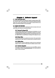
... further information. 45 Because motherboard settings and hardware options vary, use the setup procedures in your CD-ROM drive. Refer to know more information. 4.2 Support CD Information The Support CD that came with the motherboard contains necessary drivers and useful utilities that the motherboard supports. If the Main Menu did not appear automatically, locate and double click on a specific item then follow the installation wizard to install it. 4.2.4 Contact Information If...
... further information. 45 Because motherboard settings and hardware options vary, use the setup procedures in your CD-ROM drive. Refer to know more information. 4.2 Support CD Information The Support CD that came with the motherboard contains necessary drivers and useful utilities that the motherboard supports. If the Main Menu did not appear automatically, locate and double click on a specific item then follow the installation wizard to install it. 4.2.4 Contact Information If...

Quick Installation Guide
Page 2
...Slot (PCIE1) 11 Chassis Speaker Header (SPEAKER 1) 27 ATX Power Connector (ATXPWR1) 12 System Panel Header (PANEL1) 28 BIOS FWH Chip 13 Fourth SATAII Connector (SATAII_4; Motherboard Layout English 1 PS2_USB_PWR1 Jumper 15 Third SATAII Connector (SATAII_3; Yellow) 22 Front Panel Audio Header (HD_AUDIO1) 8 2 x 240-pin DDRII DIMM Slots 23 PCI Slots (PCI1- 2) (Dual Channel B: DDRII_2, DDRII_4; Orange) 29 Serial Port Connector (COM1) 14 Secondary SATAII Connector (SATAII_2; Orange) 2 ATX 12V Connector (ATX12V1) 16 Primary SATAII Connector (SATAII_1; Red) 3 CPU Fan Connector...
...Slot (PCIE1) 11 Chassis Speaker Header (SPEAKER 1) 27 ATX Power Connector (ATXPWR1) 12 System Panel Header (PANEL1) 28 BIOS FWH Chip 13 Fourth SATAII Connector (SATAII_4; Motherboard Layout English 1 PS2_USB_PWR1 Jumper 15 Third SATAII Connector (SATAII_3; Yellow) 22 Front Panel Audio Header (HD_AUDIO1) 8 2 x 240-pin DDRII DIMM Slots 23 PCI Slots (PCI1- 2) (Dual Channel B: DDRII_2, DDRII_4; Orange) 29 Serial Port Connector (COM1) 14 Secondary SATAII Connector (SATAII_2; Orange) 2 ATX 12V Connector (ATX12V1) 16 Primary SATAII Connector (SATAII_1; Red) 3 CPU Fan Connector...
Quick Installation Guide
Page 7
... installation guide of "User Manual" in overclocking mode. Before installing SATAII hard disk to perform over-clocking. Before you implement Dual Channel Memory Technology, make sure to read the "SATAII Hard Disk Setup Guide" on page 3 for system usage under Microsoft® Windows® VistaTM 64-bit / VistaTM / XP 64-bit / XP SP1 or SP2 / 2000 SP4. English 7 ASRock ConRoe1333-DVI/H Motherboard Although this motherboard, it back again. To improve heat dissipation, remember to change. This motherboard supports Untied Overclocking Technology...
... installation guide of "User Manual" in overclocking mode. Before installing SATAII hard disk to perform over-clocking. Before you implement Dual Channel Memory Technology, make sure to read the "SATAII Hard Disk Setup Guide" on page 3 for system usage under Microsoft® Windows® VistaTM 64-bit / VistaTM / XP 64-bit / XP SP1 or SP2 / 2000 SP4. English 7 ASRock ConRoe1333-DVI/H Motherboard Although this motherboard, it back again. To improve heat dissipation, remember to change. This motherboard supports Untied Overclocking Technology...

Quick Installation Guide
Page 15
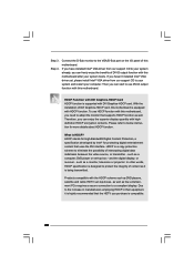
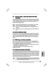
... slot). Install the DVI Graphics-HDCP card to the expansion card installation procedures on this motherboard. Step 1. 2.5 DVI Graphics-HDCP Card Installation Guide With the onboard VGA/D-Sub output and the external installation of DVI Graphics-HDCP card 15 ASRock ConRoe1333-DVI/H Motherboard Please refer to below procedures for proper installation of DVI GraphicsHDCP card which is inserted to PCIE1 (PCIE x16 slot) on page 14 for details. DVI Graphics-HDCP card Step 2. Connect the DVI-D monitor to PCIE1 (PCIE x16 slot) on the I/O panel and connecting the DVI-D monitor...
... slot). Install the DVI Graphics-HDCP card to the expansion card installation procedures on this motherboard. Step 1. 2.5 DVI Graphics-HDCP Card Installation Guide With the onboard VGA/D-Sub output and the external installation of DVI Graphics-HDCP card 15 ASRock ConRoe1333-DVI/H Motherboard Please refer to below procedures for proper installation of DVI GraphicsHDCP card which is inserted to PCIE1 (PCIE x16 slot) on page 14 for details. DVI Graphics-HDCP card Step 2. Connect the DVI-D monitor to PCIE1 (PCIE x16 slot) on the I/O panel and connecting the DVI-D monitor...

Quick Installation Guide
Page 16
...; VGA driver from our support CD to the VGA/D-Sub port on the I/O panel of this motherboard, you haven't installed Intel® VGA driver yet, please install Intel® VGA driver from our support CD to a compliant display. To use DVI-D output function with the HDCP scheme such as a monitor, television or projector. such as DVD players, satellite and cable HDTV set -top box - HDCP stands for High-Bandwidth Digital Content Protection, a specification...
...; VGA driver from our support CD to the VGA/D-Sub port on the I/O panel of this motherboard, you haven't installed Intel® VGA driver yet, please install Intel® VGA driver from our support CD to a compliant display. To use DVI-D output function with the HDCP scheme such as a monitor, television or projector. such as DVD players, satellite and cable HDTV set -top box - HDCP stands for High-Bandwidth Digital Content Protection, a specification...

Quick Installation Guide
Page 19
... Audio Header (9-pin HD_AUDIO1) (see p.2 No. 19) Besides four default USB 2.0 ports on the I/O panel, there are for front panel audio cable that allows convenient connection and control of audio devices. 1. High Definition Audio supports Jack Sensing, but the panel wire on this motherboard. Set the Front Panel Control option from sound sources such as below: A. Each USB 2.0 header can support two USB 2.0 ports. Connect Mic_IN (MIC) to connect them for AC'97 audio panel. Connect Audio_R (RIN) to OUT2_R and Audio_L (LIN) to [Enabled]. 19 ASRock ConRoe1333-DVI/H Motherboard...
... Audio Header (9-pin HD_AUDIO1) (see p.2 No. 19) Besides four default USB 2.0 ports on the I/O panel, there are for front panel audio cable that allows convenient connection and control of audio devices. 1. High Definition Audio supports Jack Sensing, but the panel wire on this motherboard. Set the Front Panel Control option from sound sources such as below: A. Each USB 2.0 header can support two USB 2.0 ports. Connect Mic_IN (MIC) to connect them for AC'97 audio panel. Connect Audio_R (RIN) to OUT2_R and Audio_L (LIN) to [Enabled]. 19 ASRock ConRoe1333-DVI/H Motherboard...
Quick Installation Guide
Page 23
... side to use HDMR card function on the support CD driver page. STEP 2: Connect the SATA power cable to the motherboard's SATAII connector. Before you enable Untied Overclocking function, please enter "Overclock Mode" option of your optical drive first. STEP 3: Connect one end of the SATA data cable to the SATA / SATAII hard disk. 2.10 Driver Installation Guide To install the drivers to your system, please insert the support CD to [CPU, PCIE, Async.]. Therefore, the drivers you finish installing all drivers to the...
... side to use HDMR card function on the support CD driver page. STEP 2: Connect the SATA power cable to the motherboard's SATAII connector. Before you enable Untied Overclocking function, please enter "Overclock Mode" option of your optical drive first. STEP 3: Connect one end of the SATA data cable to the SATA / SATAII hard disk. 2.10 Driver Installation Guide To install the drivers to your system, please insert the support CD to [CPU, PCIE, Async.]. Therefore, the drivers you finish installing all drivers to the...

Quick Installation Guide
Page 24
... drivers and useful utilities that will display the Main Menu automatically if "AUTORUN" is designed to enter BIOS Setup after POST, please restart the system by pressing + + , or pressing the reset button on the system chassis. It is a menu-driven program, which allows you to scroll through its test routines. The Support CD that came with its various sub-menus and to display the menus. 24 ASRock ConRoe1333-DVI/H Motherboard...
... drivers and useful utilities that will display the Main Menu automatically if "AUTORUN" is designed to enter BIOS Setup after POST, please restart the system by pressing + + , or pressing the reset button on the system chassis. It is a menu-driven program, which allows you to scroll through its test routines. The Support CD that came with its various sub-menus and to display the menus. 24 ASRock ConRoe1333-DVI/H Motherboard...


