User Manual
Page 26
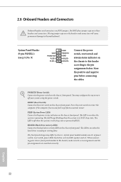
... indicator on the chassis front panel. A front panel module mainly consists of power switch, reset switch, power LED, hard drive activity LED, speaker and etc. When connecting your system using the power switch. 2.6 Onboard Headers and Connectors Onboard headers and connectors are matched correctly. You may ...assignments and the pin assignments are NOT jumpers. Do NOT place jumper caps over the headers and connectors will cause permanent damage to the motherboard. PLED (System Power LED): Connect to the pin assignments below. The LED is on when the system is in S1/S3 sleep state...
... indicator on the chassis front panel. A front panel module mainly consists of power switch, reset switch, power LED, hard drive activity LED, speaker and etc. When connecting your system using the power switch. 2.6 Onboard Headers and Connectors Onboard headers and connectors are matched correctly. You may ...assignments and the pin assignments are NOT jumpers. Do NOT place jumper caps over the headers and connectors will cause permanent damage to the motherboard. PLED (System Power LED): Connect to the pin assignments below. The LED is on when the system is in S1/S3 sleep state...

Quick Installation Guide
Page 24
Do NOT place jumper caps over the headers and connectors will cause permanent damage to the motherboard. You may differ by chassis. Note the positive and negative pins before connecting the cables. The LED is off when the system is in S4 ... restart. The LED is on the chassis front panel. A front panel module mainly consists of power switch, reset switch, power LED, hard drive activity LED, speaker and etc. Placing jumper caps over these headers and connectors. PLED (System Power LED): Connect to the pin assignments below. When connecting your system using...
Do NOT place jumper caps over the headers and connectors will cause permanent damage to the motherboard. You may differ by chassis. Note the positive and negative pins before connecting the cables. The LED is off when the system is in S4 ... restart. The LED is on the chassis front panel. A front panel module mainly consists of power switch, reset switch, power LED, hard drive activity LED, speaker and etc. Placing jumper caps over these headers and connectors. PLED (System Power LED): Connect to the pin assignments below. When connecting your system using...


