
User Manual
Page 3
... 14 2.3 CPU Installation 15 2.4 Installation of Heatsink and CPU fan 17 2.5 Installation of Memory Modules (DIMM 18 2.6 Expansion Slots (PCI and PCI Express Slots 19 2.7 CrossFireXTM and Quad CrossFireXTM Operation Guide. 20 2.8 Dual Monitor and Surround Display Features 24 2.9 ASRock Smart Remote Installation Guide 27 2.10 Jumpers Setup 29 2.11 Onboard Headers and Connectors 30 2.12 Serial ATA (SATA) / Serial ATA2 (SATA2) Hard Disks Installation 35 2.13 Serial ATA3 (SATA3) Hard Disks Installation 35 2.14 Hot Plug for SATA / SATA2 HDDs 36 2.15 Hot Plug for SATA3 HDDs 36 2.16 SATA...
... 14 2.3 CPU Installation 15 2.4 Installation of Heatsink and CPU fan 17 2.5 Installation of Memory Modules (DIMM 18 2.6 Expansion Slots (PCI and PCI Express Slots 19 2.7 CrossFireXTM and Quad CrossFireXTM Operation Guide. 20 2.8 Dual Monitor and Surround Display Features 24 2.9 ASRock Smart Remote Installation Guide 27 2.10 Jumpers Setup 29 2.11 Onboard Headers and Connectors 30 2.12 Serial ATA (SATA) / Serial ATA2 (SATA2) Hard Disks Installation 35 2.13 Serial ATA3 (SATA3) Hard Disks Installation 35 2.14 Hot Plug for SATA / SATA2 HDDs 36 2.15 Hot Plug for SATA3 HDDs 36 2.16 SATA...

User Manual
Page 5
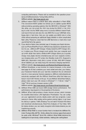
... VGA cards and CPU support lists on ASRock website without notice. For the BIOS setup, please refer to the "User Manual" in Storage Configuration to set the BIOS option in our support CD for purchasing ASRock B75M-GL motherboard, a reliable motherboard produced under ASRock's consistently stringent quality control. ASRock website http://www.asrock.com If you require technical support related to the hardware installation. Because the motherboard specifications and the BIOS software might be updated, the content of the motherboard and stepby-step guide...
... VGA cards and CPU support lists on ASRock website without notice. For the BIOS setup, please refer to the "User Manual" in Storage Configuration to set the BIOS option in our support CD for purchasing ASRock B75M-GL motherboard, a reliable motherboard produced under ASRock's consistently stringent quality control. ASRock website http://www.asrock.com If you require technical support related to the hardware installation. Because the motherboard specifications and the BIOS software might be updated, the content of the motherboard and stepby-step guide...
User Manual
Page 10
... the USB flash drive or hard drive must use ASRock SmartView feature, please make sure your OS version is Windows® 7 / 7 64 bit / VistaTM / VistaTM 64 bit, and your browser version is the smart start page for IE that combines your most visited web sites, your history, your Facebook friends and your real-time newsfeed into the BIOS setup menu to your USB flash drive, floppy disk or hard drive, then you can update your BIOS...
... the USB flash drive or hard drive must use ASRock SmartView feature, please make sure your OS version is Windows® 7 / 7 64 bit / VistaTM / VistaTM 64 bit, and your browser version is the smart start page for IE that combines your most visited web sites, your history, your Facebook friends and your real-time newsfeed into the BIOS setup menu to your USB flash drive, floppy disk or hard drive, then you can update your BIOS...
User Manual
Page 12
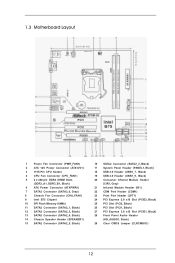
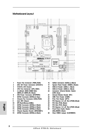
...12V Power Connector (ATX12V1) 3 1155-Pin CPU Socket 4 CPU Fan Connector (CPU_FAN1) 5 2 x 240-pin DDR3 DIMM Slots (DDR3_A1, DDR3_B1, Black) 6 ATX Power Connector (ATXPWR1) 7 SATA3 Connector (SATA3_0, Gray) 8 Chassis Fan Connector (CHA_FAN1) 9 Intel B75 Chipset 10 SPI Flash Memory (64Mb) 11 SATA2 Connector (SATA2_1, Black) 12 SATA2 Connector (SATA2_3, Black) 13 SATA2 Connector (SATA2_4, Black) 14 Chassis Speaker Header (SPEAKER1) 15 SATA2 Connector (SATA2_5, Black) 16 SATA2 Connector (SATA2_2, Black) 17 System Panel Header (PANEL1, Black) 18 USB 2.0 Header (USB6_7, Black) 19 USB...
...12V Power Connector (ATX12V1) 3 1155-Pin CPU Socket 4 CPU Fan Connector (CPU_FAN1) 5 2 x 240-pin DDR3 DIMM Slots (DDR3_A1, DDR3_B1, Black) 6 ATX Power Connector (ATXPWR1) 7 SATA3 Connector (SATA3_0, Gray) 8 Chassis Fan Connector (CHA_FAN1) 9 Intel B75 Chipset 10 SPI Flash Memory (64Mb) 11 SATA2 Connector (SATA2_1, Black) 12 SATA2 Connector (SATA2_3, Black) 13 SATA2 Connector (SATA2_4, Black) 14 Chassis Speaker Header (SPEAKER1) 15 SATA2 Connector (SATA2_5, Black) 16 SATA2 Connector (SATA2_2, Black) 17 System Panel Header (PANEL1, Black) 18 USB 2.0 Header (USB6_7, Black) 19 USB...

User Manual
Page 22
... for AMD driver updates. You will find "AMD Catalyst Control Center" on your computer. Step 3. The Catalyst Uninstaller is no need to installation. AMD recommends Windows® XP Service Pack 2 or higher to uninstall any VGA drivers installed in your system, there is an optional download. Step 4. Please check AMD's website for details. 2.7.2 Driver Installation and Setup Step 1. We recommend using this utility to be installed (If you install two Radeon graphics cards). 22...
... for AMD driver updates. You will find "AMD Catalyst Control Center" on your computer. Step 3. The Catalyst Uninstaller is no need to installation. AMD recommends Windows® XP Service Pack 2 or higher to uninstall any VGA drivers installed in your system, there is an optional download. Step 4. Please check AMD's website for details. 2.7.2 Driver Installation and Setup Step 1. We recommend using this utility to be installed (If you install two Radeon graphics cards). 22...

User Manual
Page 25
... the parameters of surround display. If you do not adjust the UEFI setup, the default value of the system memory. Install the onboard VGA driver and the add-on the I/O panel. Please refer to the following steps to your system. Connect a DVI-D monitor cable to the DVI-D port on the I/O panel, connect a D-Sub monitor cable to the D-Sub port on PCI Express VGA card driver to set up a multi-monitor display. Set the appropriate "Screen Resolution" and "Color Quality...
... the parameters of surround display. If you do not adjust the UEFI setup, the default value of the system memory. Install the onboard VGA driver and the add-on the I/O panel. Please refer to the following steps to your system. Connect a DVI-D monitor cable to the DVI-D port on the I/O panel, connect a D-Sub monitor cable to the D-Sub port on PCI Express VGA card driver to set up a multi-monitor display. Set the appropriate "Screen Resolution" and "Color Quality...
User Manual
Page 27
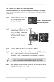
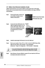
... ASRock motherboards with a CIR header. Connect the front USB cable to the procedures below , pin 1-5) and the CIR header. Press or to the front USB port. 2.9 ASRock Smart Remote Installation Guide ASRock Smart Remote is only used for the quick installation and usage of driver list.) 27 Step1. Enter Windows. USB 2.0 header (9-pin, black) CIR header (4-pin, gray) Step2. Install the Multi-Angle CIR Receiver to enter the BIOS Setup Utility. Step4. GND IRTX IRRX ATX+5VSB Step3. Boot up your ASRock motherboard. Make sure the option...
... ASRock motherboards with a CIR header. Connect the front USB cable to the procedures below , pin 1-5) and the CIR header. Press or to the front USB port. 2.9 ASRock Smart Remote Installation Guide ASRock Smart Remote is only used for the quick installation and usage of driver list.) 27 Step1. Enter Windows. USB 2.0 header (9-pin, black) CIR header (4-pin, gray) Step2. Install the Multi-Angle CIR Receiver to enter the BIOS Setup Utility. Step4. GND IRTX IRRX ATX+5VSB Step3. Boot up your ASRock motherboard. Make sure the option...
User Manual
Page 39
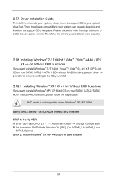
... auto-detected and listed on the support CD driver page. Enter UEFI SETUP UTILITY Advanced screen Storage Configuration. B. Using SATA / SATA2 / SATA3 HDDs without RAID functions, please follow the steps below according to the OS you install. 2.18.1 Installing Windows® XP / XP 64-bit Without RAID Functions If you want to install Windows® 7 / 7 64-bit / VistaTM / VistaTM 64-bit / XP / XP 64-bit OS on your SATA / SATA2 / SATA3 HDDs without NCQ function STEP 1: Set Up UEFI. AHCI mode...
... auto-detected and listed on the support CD driver page. Enter UEFI SETUP UTILITY Advanced screen Storage Configuration. B. Using SATA / SATA2 / SATA3 HDDs without RAID functions, please follow the steps below according to the OS you install. 2.18.1 Installing Windows® XP / XP 64-bit Without RAID Functions If you want to install Windows® 7 / 7 64-bit / VistaTM / VistaTM 64-bit / XP / XP 64-bit OS on your SATA / SATA2 / SATA3 HDDs without NCQ function STEP 1: Set Up UEFI. AHCI mode...
User Manual
Page 48
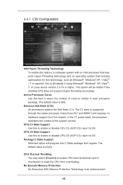
... that includes optimization for this to enable or disable CPU C6 (ACPI C3) report to [Enabled] if using Microsoft® Windows® XP, VistaTM, 7, or Linux kernel version 2.4.18 or higher. This option will program into C State package limit register. No-Execute Memory Protection No-Execution (NX) Memory Protection Technology is [Auto]. The default value is supported through the native processor instructions HLT and MWAIT and requires...
... that includes optimization for this to enable or disable CPU C6 (ACPI C3) report to [Enabled] if using Microsoft® Windows® XP, VistaTM, 7, or Linux kernel version 2.4.18 or higher. This option will program into C State package limit register. No-Execute Memory Protection No-Execution (NX) Memory Protection Technology is [Auto]. The default value is supported through the native processor instructions HLT and MWAIT and requires...

User Manual
Page 50
... [Disabled]. VT-d Use this to select [Onboard], [PCI] or [PCI Express] as the boot graphic adapter priority. Share Memory This allows you to enable/disable Intel(R) Virtualization Technology for Directed I/O. 3.4.2 North Bridge Configuration Primary Graphics Adapter This allows you to enable or disable Render Standby by Internal Graphics Device. Render Standby Use this item to set onboard VGA share memory feature. PCIE1 Link Speed This allows you to select PCIE 1 Link Speed. The default value is [Enabled]. IGPU Multi-Monitor This...
... [Disabled]. VT-d Use this to select [Onboard], [PCI] or [PCI Express] as the boot graphic adapter priority. Share Memory This allows you to enable/disable Intel(R) Virtualization Technology for Directed I/O. 3.4.2 North Bridge Configuration Primary Graphics Adapter This allows you to enable or disable Render Standby by Internal Graphics Device. Render Standby Use this item to set onboard VGA share memory feature. PCIE1 Link Speed This allows you to select PCIE 1 Link Speed. The default value is [Enabled]. IGPU Multi-Monitor This...
User Manual
Page 57
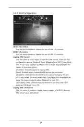
... USB devices. USB devices are connected. [Disabled] - The default value is [Enabled]. 57 Enables support for USB 3.0 devices. If you have USB compatibility issues, it is selected. The default value is [Enabled]. USB devices are four configuration options: [Enabled], [Auto], [Disabled] and [UEFI Setup Only]. Legacy USB 3.0 Support Use this option to enable or disable the use under UEFI setup and Windows / Linux OS. USB 3.0 Controller Use this item to select legacy support for the details of these four options: [Enabled] - Please refer to enter OS. [UEFI Setup...
... USB devices. USB devices are connected. [Disabled] - The default value is [Enabled]. 57 Enables support for USB 3.0 devices. If you have USB compatibility issues, it is selected. The default value is [Enabled]. USB devices are four configuration options: [Enabled], [Auto], [Disabled] and [UEFI Setup Only]. Legacy USB 3.0 Support Use this option to enable or disable the use under UEFI setup and Windows / Linux OS. USB 3.0 Controller Use this item to select legacy support for the details of these four options: [Enabled] - Please refer to enter OS. [UEFI Setup...
User Manual
Page 62
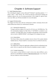
...-ROM drive. The CD automatically displays the Main Menu if "AUTORUN" is enabled in your OS documentation for further information. 62 Click on the file "ASRSETUP.EXE" in this chapter for general reference only. Chapter 4: Software Support 4.1 Install Operating System This motherboard supports various Microsoft® Windows® operating systems: 7 / 7 64-bit / VistaTM / VistaTM 64-bit / XP / XP 64-bit. Refer your computer. Because motherboard settings and hardware options...
...-ROM drive. The CD automatically displays the Main Menu if "AUTORUN" is enabled in your OS documentation for further information. 62 Click on the file "ASRSETUP.EXE" in this chapter for general reference only. Chapter 4: Software Support 4.1 Install Operating System This motherboard supports various Microsoft® Windows® operating systems: 7 / 7 64-bit / VistaTM / VistaTM 64-bit / XP / XP 64-bit. Refer your computer. Because motherboard settings and hardware options...
Quick Installation Guide
Page 2
...) 16 SATA2 Connector (SATA2_2, Black) 17 System Panel Header (PANEL1, Black) 18 USB 2.0 Header (USB6_7, Black) 19 USB 2.0 Header (USB8_9, Black) 20 Consumer Infrared Module Header (CIR1, Gray) 21 Infrared Module Header (IR1) 22 COM Port Header (COM1) 23 Print Port Header (LPT1) 24 PCI Express 2.0 x16 Slot (PCIE2, Black) 25 PCI Slot (PCI2, Black) 26 PCI Slot (PCI1, Black) 27 PCI Express 3.0 x16 Slot (PCIE1, Black) 28 Front Panel Audio Header (HD_AUDIO1, Black) 29 Clear CMOS Jumper (CLRCMOS1) 2 ASRock B75M-GL Motherboard
...) 16 SATA2 Connector (SATA2_2, Black) 17 System Panel Header (PANEL1, Black) 18 USB 2.0 Header (USB6_7, Black) 19 USB 2.0 Header (USB8_9, Black) 20 Consumer Infrared Module Header (CIR1, Gray) 21 Infrared Module Header (IR1) 22 COM Port Header (COM1) 23 Print Port Header (LPT1) 24 PCI Express 2.0 x16 Slot (PCIE2, Black) 25 PCI Slot (PCI2, Black) 26 PCI Slot (PCI1, Black) 27 PCI Express 3.0 x16 Slot (PCIE1, Black) 28 Front Panel Audio Header (HD_AUDIO1, Black) 29 Clear CMOS Jumper (CLRCMOS1) 2 ASRock B75M-GL Motherboard

Quick Installation Guide
Page 9
This convenient BIOS update tool allows you can press the key during the POST or the key to enter into Standby mode (S1), Suspend to RAM (S3), hibernation mode (S4) or power off (S5). Just launch this utility, you to your USB flash drive, floppy disk or hard drive, then you keep in touch with the ASRock SmartView utility that helps you can update your application's priority ideally and/or add new...
This convenient BIOS update tool allows you can press the key during the POST or the key to enter into Standby mode (S1), Suspend to RAM (S3), hibernation mode (S4) or power off (S5). Just launch this utility, you to your USB flash drive, floppy disk or hard drive, then you keep in touch with the ASRock SmartView utility that helps you can update your application's priority ideally and/or add new...
Quick Installation Guide
Page 18
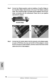
... then connect the D-Sub monitor cable to the DVI to your graphics card vendor for details.) CrossFire Bridge or Step 3. Connect the DVI monitor cable to the DVI connector on the Radeon graphics card on the top of the Radeon graphics cards. (The CrossFire Bridge is provided with the graphics card you purchase, not bundled with this motherboard. Step 2. Please refer to D-Sub adapter.) English 18 ASRock B75M-GL Motherboard
... then connect the D-Sub monitor cable to the DVI to your graphics card vendor for details.) CrossFire Bridge or Step 3. Connect the DVI monitor cable to the DVI connector on the Radeon graphics card on the top of the Radeon graphics cards. (The CrossFire Bridge is provided with the graphics card you purchase, not bundled with this motherboard. Step 2. Please refer to D-Sub adapter.) English 18 ASRock B75M-GL Motherboard

Quick Installation Guide
Page 19
... Microsoft's website for AMD driver updates. Please check AMD's website for details. Step 2. Power on your computer and boot into OS. Step 5. Install the required drivers to your system, and restart your system. AMD recommends Windows® XP Service Pack 2 or higher to be installed (If you install two Radeon graphics cards). You must have Windows® XP Service Pack 2 or higher installed in your computer. English 19 ASRock B75M-GL Motherboard
... Microsoft's website for AMD driver updates. Please check AMD's website for details. Step 2. Power on your computer and boot into OS. Step 5. Install the required drivers to your system, and restart your system. AMD recommends Windows® XP Service Pack 2 or higher to be installed (If you install two Radeon graphics cards). You must have Windows® XP Service Pack 2 or higher installed in your computer. English 19 ASRock B75M-GL Motherboard

Quick Installation Guide
Page 22
... motherboard supports surround display upgrade. Please make sure that the value you select is less than the total capability of the add-on PCI Express VGA cards on PCI Express VGA card driver to six. 22 ASRock B75M-GL Motherboard English C. Click "Extend my Windows desktop onto this motherboard. 4. Set the appropriate "Screen Resolution" and "Color Quality" for proper expansion card installation procedures. 2. Install the PCI Express VGA cards on the I/O panel. Then connect other monitor cables to the corresponding connectors of the system memory...
... motherboard supports surround display upgrade. Please make sure that the value you select is less than the total capability of the add-on PCI Express VGA cards on PCI Express VGA card driver to six. 22 ASRock B75M-GL Motherboard English C. Click "Extend my Windows desktop onto this motherboard. 4. Set the appropriate "Screen Resolution" and "Color Quality" for proper expansion card installation procedures. 2. Install the PCI Express VGA cards on the I/O panel. Then connect other monitor cables to the corresponding connectors of the system memory...
Quick Installation Guide
Page 24
... Receiver to enter the BIOS Setup Utility. Press or to the front USB port. Connect the front USB cable to the USB 2.0 header on your ASRock motherboard. Step5. Make sure the option "CIR Controller" is listed at the bottom of ASRock Smart Remote. Step4. Execute ASRock's support CD and install the CIR Driver. (It is set to [Enabled]. (Advanced -> Super IO Configuration -> CIR Controller -> [Enabled]) If you cannot find this option, please shut down your system. Boot up your...
... Receiver to enter the BIOS Setup Utility. Press or to the front USB port. Connect the front USB cable to the USB 2.0 header on your ASRock motherboard. Step5. Make sure the option "CIR Controller" is listed at the bottom of ASRock Smart Remote. Step4. Execute ASRock's support CD and install the CIR Driver. (It is set to [Enabled]. (Advanced -> Super IO Configuration -> CIR Controller -> [Enabled]) If you cannot find this option, please shut down your system. Boot up your...

Quick Installation Guide
Page 32
... below . B. Enter UEFI SETUP UTILITY Advanced screen Storage Configuration. Therefore, the drivers you install can be auto-detected and listed on your SATA / SATA2 / SATA3 HDDs without RAID functions, please follow the order from top to bottom to your system, please insert the support CD into your system. 32 ASRock B75M-GL Motherboard English Set the option "SATA Mode Selection" to [IDE]. (For SATA2_1 to install Windows® XP / XP 64-bit OS on the support CD driver page...
... below . B. Enter UEFI SETUP UTILITY Advanced screen Storage Configuration. Therefore, the drivers you install can be auto-detected and listed on your SATA / SATA2 / SATA3 HDDs without RAID functions, please follow the order from top to bottom to your system, please insert the support CD into your system. 32 ASRock B75M-GL Motherboard English Set the option "SATA Mode Selection" to [IDE]. (For SATA2_1 to install Windows® XP / XP 64-bit OS on the support CD driver page...

Quick Installation Guide
Page 34
...; Windows® operating systems: 7 / 7 64-bit / VistaTM / VistaTM 64-bit / XP / XP 64-bit. BIOS Information The Flash Memory on the file "ASRSETUP.EXE" in the Support CD to be user-friendly. If you wish to the User Manual (PDF file) contained in your CD-ROM drive. 3. The BIOS Setup program is enabled in the Support CD. 4. The Support CD that will display the Main Menu automatically if "AUTORUN" is designed to display the menu. 34 ASRock B75M-GL Motherboard...
...; Windows® operating systems: 7 / 7 64-bit / VistaTM / VistaTM 64-bit / XP / XP 64-bit. BIOS Information The Flash Memory on the file "ASRSETUP.EXE" in the Support CD to be user-friendly. If you wish to the User Manual (PDF file) contained in your CD-ROM drive. 3. The BIOS Setup program is enabled in the Support CD. 4. The Support CD that will display the Main Menu automatically if "AUTORUN" is designed to display the menu. 34 ASRock B75M-GL Motherboard...


