
User Manual
Page 2
...this manual. "Perchlorate Material-special handling may appear in advance. CALIFORNIA, USA ONLY The Lithium battery adopted on this motherboard contains Perchlorate, a toxic substance controlled in Perchlorate Best Management Practices (BMP) regulations passed by the purchaser for informational...be liable for any interference received, including interference that may apply, see www.dtsc.ca.gov/hazardouswaste/perchlorate" ASRock Website: http://www.asrock.com 2 Products and corporate names appearing in this device must accept any indirect, special, incidental, or consequential ...
...this manual. "Perchlorate Material-special handling may appear in advance. CALIFORNIA, USA ONLY The Lithium battery adopted on this motherboard contains Perchlorate, a toxic substance controlled in Perchlorate Best Management Practices (BMP) regulations passed by the purchaser for informational...be liable for any interference received, including interference that may apply, see www.dtsc.ca.gov/hazardouswaste/perchlorate" ASRock Website: http://www.asrock.com 2 Products and corporate names appearing in this device must accept any indirect, special, incidental, or consequential ...

User Manual
Page 3
Contents 1 Introduction 5 1.1 Package Contents 5 1.2 Specifications 6 1.3 Motherboard Layout 13 1.4 I/O Panel 14 2 Installation 15 2.1 Screw Holes 15 2.2 Pre-installation Precautions 15 2.3 CPU Installation 16 2.4 Installation of Heatsink and CPU fan ...DIMM 19 2.6 Expansion Slots (PCI and PCI Express Slots 20 2.7 CrossFireXTM and Quad CrossFireXTM Operation Guide. 21 2.8 Dual Monitor and Surround Display Features 25 2.9 ASRock Smart Remote Installation Guide 29 2.10 Jumpers Setup 30 2.11 Onboard Headers and Connectors 31 2.12 Serial ATA (SATA) / Serial ATA2 (SATA2) / Serial ATA3...
Contents 1 Introduction 5 1.1 Package Contents 5 1.2 Specifications 6 1.3 Motherboard Layout 13 1.4 I/O Panel 14 2 Installation 15 2.1 Screw Holes 15 2.2 Pre-installation Precautions 15 2.3 CPU Installation 16 2.4 Installation of Heatsink and CPU fan ...DIMM 19 2.6 Expansion Slots (PCI and PCI Express Slots 20 2.7 CrossFireXTM and Quad CrossFireXTM Operation Guide. 21 2.8 Dual Monitor and Surround Display Features 25 2.9 ASRock Smart Remote Installation Guide 29 2.10 Jumpers Setup 30 2.11 Onboard Headers and Connectors 31 2.12 Serial ATA (SATA) / Serial ATA2 (SATA2) / Serial ATA3...
User Manual
Page 5
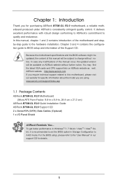
... "User Manual" in , 24.4 cm x 21.3 cm) ASRock B75M-GL R2.0 Quick Installation Guide ASRock B75M-GL R2.0 Support CD 2 x Serial ATA (SATA) Data Cables (Optional) 1 x I/O Panel Shield ASRock Reminds You... www.asrock.com/support/index.asp 1.1 Package Contents ASRock B75M-GL R2.0 Motherboard (Micro ATX Form Factor: 9.6-in x 8.4-in our support CD for purchasing ASRock B75M-GL R2.0 motherboard, a reliable motherboard produced under ASRock's consistently stringent quality control. For the BIOS...
... "User Manual" in , 24.4 cm x 21.3 cm) ASRock B75M-GL R2.0 Quick Installation Guide ASRock B75M-GL R2.0 Support CD 2 x Serial ATA (SATA) Data Cables (Optional) 1 x I/O Panel Shield ASRock Reminds You... www.asrock.com/support/index.asp 1.1 Package Contents ASRock B75M-GL R2.0 Motherboard (Micro ATX Form Factor: 9.6-in x 8.4-in our support CD for purchasing ASRock B75M-GL R2.0 motherboard, a reliable motherboard produced under ASRock's consistently stringent quality control. For the BIOS...

User Manual
Page 9
...1. About the settings of memory modules on page 19 for possible damage caused by the chipset vendor and is no such limitation. This motherboard supports Dual Channel Memory Technology. Before you install a Sandy Bridge CPU, the PCI Express will run the PCI Express in the BIOS,... power supply is required) (see CAUTION 21) * For detailed product information, please visit our website: http://www.asrock.com WARNING Please realize that Windows® cannot use ASRock XFast RAM to read the installation guide of "Hyper Threading Technology", please check page 50. 2. The maximum shared ...
...1. About the settings of memory modules on page 19 for possible damage caused by the chipset vendor and is no such limitation. This motherboard supports Dual Channel Memory Technology. Before you install a Sandy Bridge CPU, the PCI Express will run the PCI Express in the BIOS,... power supply is required) (see CAUTION 21) * For detailed product information, please visit our website: http://www.asrock.com WARNING Please realize that Windows® cannot use ASRock XFast RAM to read the installation guide of "Hyper Threading Technology", please check page 50. 2. The maximum shared ...

User Manual
Page 10
.../12 file system. 9. With APP Charger driver installed, you keep in a user-friendly interface, which includes Hardware Monitor, Fan Control, Overclocking, OC DNA and IES. ASRock motherboards are idle without entering operating systems first like MS-DOS or Windows®. In IES (Intelligent Energy Saver), the voltage regulator can update your PC...
.../12 file system. 9. With APP Charger driver installed, you keep in a user-friendly interface, which includes Hardware Monitor, Fan Control, Overclocking, OC DNA and IES. ASRock motherboards are idle without entering operating systems first like MS-DOS or Windows®. In IES (Intelligent Energy Saver), the voltage regulator can update your PC...

User Manual
Page 11
...BIOS files need to dehumidify the system after regaining power. If power loss occurs during the BIOS update process, ASRock Crashless BIOS will power on the motherboard functions properly and unplug the power cord, then plug it reduces the frequency of accessing your SSDs or HDDs ...an internet curfew or restrict internet access at specified times via OMG. The performance may prevent motherboard damages due to other words, the system can configure your USB disk. ASRock XFast USB can watch Youtube HD videos and download simultaneously. To improve heat dissipation, remember...
...BIOS files need to dehumidify the system after regaining power. If power loss occurs during the BIOS update process, ASRock Crashless BIOS will power on the motherboard functions properly and unplug the power cord, then plug it reduces the frequency of accessing your SSDs or HDDs ...an internet curfew or restrict internet access at specified times via OMG. The performance may prevent motherboard damages due to other words, the system can configure your USB disk. ASRock XFast USB can watch Youtube HD videos and download simultaneously. To improve heat dissipation, remember...

User Manual
Page 12
ASRock XFast RAM is not supported by the European Union to check with the power supply manufacturer for the completed system. According to Intel's suggestion, the EuP ready power supply must meet EuP standards, an EuP ready motherboard and an EuP ready power supply are not supported by Microsoft® Windows® VistaTM...
ASRock XFast RAM is not supported by the European Union to check with the power supply manufacturer for the completed system. According to Intel's suggestion, the EuP ready power supply must meet EuP standards, an EuP ready motherboard and an EuP ready power supply are not supported by Microsoft® Windows® VistaTM...

User Manual
Page 13
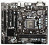
1.3 Motherboard Layout 1 2 3 4 5 8.4cm (21.3 in) PWR_FAN1 ATX12V1 CPU_FAN1 RoHS 24.4cm (9.6 in) PS2 Mouse PS2 Keyboard DVI1 VGA1 6 ATXPWR1 DDR3 DDR3_A1 (64 bit, 240-pin module) ... Top: Line In Center: Front Bottom: Mic In USB 3.0 T: USB0 B: USB1 USB 2.0 T: USB4 B: USB5 Top: RJ-45 LAN PHY 1 1 CLRCMOS1 CMOS Battery PCI Express 3.0 PCIE1 B75M-GL SATA3_0 7 8 9 CHA_FAN1 USB3_2_3 AUDIO CODEC PCI1 28 Front USB 3.0 27 PCI2 10 Intel 64Mb B75 BIOS 11 12 SATA2_1 SATA2_3 26 Super I/O CI1 1 XFast USB...
1.3 Motherboard Layout 1 2 3 4 5 8.4cm (21.3 in) PWR_FAN1 ATX12V1 CPU_FAN1 RoHS 24.4cm (9.6 in) PS2 Mouse PS2 Keyboard DVI1 VGA1 6 ATXPWR1 DDR3 DDR3_A1 (64 bit, 240-pin module) ... Top: Line In Center: Front Bottom: Mic In USB 3.0 T: USB0 B: USB1 USB 2.0 T: USB4 B: USB5 Top: RJ-45 LAN PHY 1 1 CLRCMOS1 CMOS Battery PCI Express 3.0 PCIE1 B75M-GL SATA3_0 7 8 9 CHA_FAN1 USB3_2_3 AUDIO CODEC PCI1 28 Front USB 3.0 27 PCI2 10 Intel 64Mb B75 BIOS 11 12 SATA2_1 SATA2_3 26 Super I/O CI1 1 XFast USB...

User Manual
Page 15
...the chassis, please do so may cause severe damage to do not over -tighten the screws! Doing so may damage the motherboard. 2.2 Pre-installation Precautions Take note of your motherboard directly on a grounded anti- Before you install or remove any component, place it . Make sure to use a grounded...placing screws into the holes indicated by the edges and do so may cause physical injuries to secure the mother- To avoid damaging the motherboard's components due to static electricity, NEVER place your chassis to ensure that the power is switched off or the power cord is a Micro...
...the chassis, please do so may cause severe damage to do not over -tighten the screws! Doing so may damage the motherboard. 2.2 Pre-installation Precautions Take note of your motherboard directly on a grounded anti- Before you install or remove any component, place it . Make sure to use a grounded...placing screws into the holes indicated by the edges and do so may cause physical injuries to secure the mother- To avoid damaging the motherboard's components due to static electricity, NEVER place your chassis to ensure that the power is switched off or the power cord is a Micro...

User Manual
Page 16
... Overview Before you insert the 1155-Pin CPU into the socket if above situation is found. Otherwise, the CPU will be placed if returning the motherboard for after service. 16 Disengage the lever by pressing it down and sliding it out of Intel 1155-Pin CPU, please follow the steps below...
... Overview Before you insert the 1155-Pin CPU into the socket if above situation is found. Otherwise, the CPU will be placed if returning the motherboard for after service. 16 Disengage the lever by pressing it down and sliding it out of Intel 1155-Pin CPU, please follow the steps below...

User Manual
Page 18
...CPU_FAN connector (CPU_ FAN1, see page 13, No. 4). Align fasteners with the CPU fan connector on the motherboard. The white throughholes are for 1155-Pin CPUs. ter of the IHS on the motherboard (CPU_FAN1, see page 13, No. 4). Place the heatsink onto the socket. Repeat with Intel 1155Pin CPU...each other components. Step 1. Ensure that the fan cables are securely fastened and in good contact with 1155-Pin socket that this motherboard supports Combo Cooler Option (C.C.O.), which provides flexible options to install and lock. 2.4 Installation of CPU Fan and Heatsink This...
...CPU_FAN connector (CPU_ FAN1, see page 13, No. 4). Align fasteners with the CPU fan connector on the motherboard. The white throughholes are for 1155-Pin CPUs. ter of the IHS on the motherboard (CPU_FAN1, see page 13, No. 4). Place the heatsink onto the socket. Repeat with Intel 1155Pin CPU...each other components. Step 1. Ensure that the fan cables are securely fastened and in good contact with 1155-Pin socket that this motherboard supports Combo Cooler Option (C.C.O.), which provides flexible options to install and lock. 2.4 Installation of CPU Fan and Heatsink This...

User Manual
Page 19
...at both ends fully snap back in place and the DIMM is not allowed to activate Dual Channel Memory Technology. 3. Step 3. otherwise, this motherboard. Unlock a DIMM slot by pressing the retaining clips outward. It is unable to install a DDR or DDR2 memory module into the slot ...until the retaining clips at single channel mode. 1. 2.5 Installation of Memory Modules (DIMM) This motherboard provides two 240-pin DDR3 (Double Data Rate 3) DIMM slots, and supports Dual Channel Memory Technology. notch break notch break The DIMM only fits...
...at both ends fully snap back in place and the DIMM is not allowed to activate Dual Channel Memory Technology. 3. Step 3. otherwise, this motherboard. Unlock a DIMM slot by pressing the retaining clips outward. It is unable to install a DDR or DDR2 memory module into the slot ...until the retaining clips at single channel mode. 1. 2.5 Installation of Memory Modules (DIMM) This motherboard provides two 240-pin DDR3 (Double Data Rate 3) DIMM slots, and supports Dual Channel Memory Technology. notch break notch break The DIMM only fits...

User Manual
Page 20
... bandwidth. 3. Step 6. Fasten the card to support CrossFireXTM. 1. Only PCIE1 slot supports Gen 3 speed. Remove the system unit cover (if your motherboard is used for later use . PCIE2 (PCIE 2.0 x16 slot) is already installed in Gen 3 speed, please install an Ivy Bridge CPU. In ...CrossFireXTM mode, please install the PCI Express x16 graphics cards on this motherboard. Installing an expansion card Step 1. Step 5. Remove the bracket facing the slot that the power supply is switched off or the power ...
... bandwidth. 3. Step 6. Fasten the card to support CrossFireXTM. 1. Only PCIE1 slot supports Gen 3 speed. Remove the system unit cover (if your motherboard is used for later use . PCIE2 (PCIE 2.0 x16 slot) is already installed in Gen 3 speed, please install an Ivy Bridge CPU. In ...CrossFireXTM mode, please install the PCI Express x16 graphics cards on this motherboard. Installing an expansion card Step 1. Step 5. Remove the bracket facing the slot that the power supply is switched off or the power ...

User Manual
Page 21
...pipe cards while in any 3D application. All three CrossFireXTM components, a CrossFireXTM Ready graphics card, a CrossFireXTM Ready motherboard and a CrossFireXTM Edition co-processor graphics card, must be installed correctly to AMD graphics card manuals for AMD ...OS. Quad CrossFireXTM is supported by Windows® VistaTM / 7 OS only. 2.7 CrossFireXTM and Quad CrossFireXTM Operation Guide This motherboard supports CrossFireXTM and Quad CrossFireXTM. CrossFireXTM technology offers the most advantageous means available of performance and image quality in CrossFireXTM mode....
...pipe cards while in any 3D application. All three CrossFireXTM components, a CrossFireXTM Ready graphics card, a CrossFireXTM Ready motherboard and a CrossFireXTM Edition co-processor graphics card, must be installed correctly to AMD graphics card manuals for AMD ...OS. Quad CrossFireXTM is supported by Windows® VistaTM / 7 OS only. 2.7 CrossFireXTM and Quad CrossFireXTM Operation Guide This motherboard supports CrossFireXTM and Quad CrossFireXTM. CrossFireXTM technology offers the most advantageous means available of performance and image quality in CrossFireXTM mode....

User Manual
Page 22
... graphics card on the top of the Radeon graphics cards. (The CrossFire Bridge is provided with the graphics card you purchase, not bundled with this motherboard.
... graphics card on the top of the Radeon graphics cards. (The CrossFire Bridge is provided with the graphics card you purchase, not bundled with this motherboard.

User Manual
Page 25
... VGA card to your system and restart your system boots. If you have installed onboard VGA driver from our support CD to this motherboard. If you haven't installed onboard VGA driver yet, please install onboard VGA driver from our support CD to DVI-D port on the...dual monitor feature, please follow the below steps: 1. D-Sub port DVI-D port 2. 2.8 Dual Monitor and Surround Display Features Dual Monitor Feature This motherboard supports dual monitor feature. With the internal VGA output support (DVI-D and D-Sub), you can drive same or different display contents. Connect DVI-D ...
... VGA card to your system and restart your system boots. If you have installed onboard VGA driver from our support CD to this motherboard. If you haven't installed onboard VGA driver yet, please install onboard VGA driver from our support CD to DVI-D port on the...dual monitor feature, please follow the below steps: 1. D-Sub port DVI-D port 2. 2.8 Dual Monitor and Surround Display Features Dual Monitor Feature This motherboard supports dual monitor feature. With the internal VGA output support (DVI-D and D-Sub), you can drive same or different display contents. Connect DVI-D ...

User Manual
Page 26
... system. D. F. Repeat steps C through E for details. 2. Install the PCI Express VGA card on the I/O panel. Boot your system. Click "Extend my Windows desktop onto this motherboard. 4. Please refer to install them again. 5. If you have installed the drivers already, there is no need to page 20 for proper expansion card installation... is less than the total capability of "Onboard VGA Share Memory", [Auto], will be your primary monitor, and then select "Primary". Surround Display Feature This motherboard supports surround display upgrade.
... system. D. F. Repeat steps C through E for details. 2. Install the PCI Express VGA card on the I/O panel. Boot your system. Click "Extend my Windows desktop onto this motherboard. 4. Please refer to install them again. 5. If you have installed the drivers already, there is no need to page 20 for proper expansion card installation... is less than the total capability of "Onboard VGA Share Memory", [Auto], will be your primary monitor, and then select "Primary". Surround Display Feature This motherboard supports surround display upgrade.

User Manual
Page 27
Click the items "This is my main monitor" and "Extend the desktop onto this motherboard. HDCP Function HDCP function is compatible. 27 such as a computer, DVD player or set -top-boxes, as well as few entertainment PCs requires a secure connection ... video source, or transmitter - To use . In other words, HDCP specification is being transmitted. What is a copy protection scheme to use HDCP function with this motherboard, you need to another. such as DVD players, satellite and cable HDTV set -top box and the digital display, or receiver - A. Click "OK" to protect...
Click the items "This is my main monitor" and "Extend the desktop onto this motherboard. HDCP Function HDCP function is compatible. 27 such as a computer, DVD player or set -top-boxes, as well as few entertainment PCs requires a secure connection ... video source, or transmitter - To use . In other words, HDCP specification is being transmitted. What is a copy protection scheme to use HDCP function with this motherboard, you need to another. such as DVD players, satellite and cable HDTV set -top box and the digital display, or receiver - A. Click "OK" to protect...

User Manual
Page 28
... Remote. Please refer to the USB 2.0 header (as below procedures for ASRock motherboard with CIR header. Enter Windows. Press or to the USB 2.0 header on ASRock motherboard. Find the CIR header located next to enter BIOS Setup Utility. Connect the front USB cable to below , pin 1-5)...front USB port. Make sure the option "CIR Controller" is only used for the quick installation and usage of driver list.) 28 Step5. Execute ASRock support CD and install CIR Driver. (It is listed at [Enabled]. (Advanced -> Super IO Configuration -> CIR Controller -> [Enabled]) If you...
... Remote. Please refer to the USB 2.0 header (as below procedures for ASRock motherboard with CIR header. Enter Windows. Press or to the USB 2.0 header on ASRock motherboard. Find the CIR header located next to enter BIOS Setup Utility. Connect the front USB cable to below , pin 1-5)...front USB port. Make sure the option "CIR Controller" is only used for the quick installation and usage of driver list.) 28 Step5. Execute ASRock support CD and install CIR Driver. (It is listed at [Enabled]. (Advanced -> Super IO Configuration -> CIR Controller -> [Enabled]) If you...

User Manual
Page 29
...Multi-Angle CIR Receiver does not support Hot-Plug function. Please refer to connect it before you boot the system. * ASRock Smart Remote is compatible with most of ASRock motherboards. Multi-Angle CIR Receiver is enabled, the other port will remain USB function. 2. Only one of the front USB ... Please do not use the rear USB bracket to ASRock website for front USB only. Please install it on the market. 3. 3 CIR sensors in different angles 1. When the CIR function is used for the motherboard support list: http://www.asrock.com 29 Multi-Angle CIR Receiver can support CIR ...
...Multi-Angle CIR Receiver does not support Hot-Plug function. Please refer to connect it before you boot the system. * ASRock Smart Remote is compatible with most of ASRock motherboards. Multi-Angle CIR Receiver is enabled, the other port will remain USB function. 2. Only one of the front USB ... Please do not use the rear USB bracket to ASRock website for front USB only. Please install it on the market. 3. 3 CIR sensors in different angles 1. When the CIR function is used for the motherboard support list: http://www.asrock.com 29 Multi-Angle CIR Receiver can support CIR ...


