
RAID Installation Guide
Page 2
... use the onboard RAID Option ROM Utility to configure RAID. 1.1 Introduction to RAID The term "RAID" stands for you can improve the access performance, it contains a complete copy of the "User Manual" in our support CD, then you to the surviving drive as a single drive but at a sustained data transfer rate. 1. AMD BIOS RAID Installation Guide AMD BIOS RAID Installation Guide is called data mirroring that optimizes two identical hard disk drives to RAID mode by using the onboard FastBuild BIOS utility under BIOS environment. Hot-Plug...
... use the onboard RAID Option ROM Utility to configure RAID. 1.1 Introduction to RAID The term "RAID" stands for you can improve the access performance, it contains a complete copy of the "User Manual" in our support CD, then you to the surviving drive as a single drive but at a sustained data transfer rate. 1. AMD BIOS RAID Installation Guide AMD BIOS RAID Installation Guide is called data mirroring that optimizes two identical hard disk drives to RAID mode by using the onboard FastBuild BIOS utility under BIOS environment. Hot-Plug...

RAID Installation Guide
Page 8
... click . B. Plug a USB drive into the DVD-ROM drive. Go to finish the driver copy process. Please download the "SATA Floppy Imaged driver" from ASRock's website A. D. Insert the Support CD into one of the USB port. Please install the DVD-ROM. C. Click to find the driver inside your USB flash disk. A. STEP 3.2: Download driver from ASRock's website and unzip the file into your USB flash drive. 8 During system boot, press or key to finish the configuration. STEP 4: Windows installation A. STEP 3.1: Copy RAID driver to a USB flash drive You can...
... click . B. Plug a USB drive into the DVD-ROM drive. Go to finish the driver copy process. Please download the "SATA Floppy Imaged driver" from ASRock's website A. D. Insert the Support CD into one of the USB port. Please install the DVD-ROM. C. Click to find the driver inside your USB flash disk. A. STEP 3.2: Download driver from ASRock's website and unzip the file into your USB flash drive. 8 During system boot, press or key to finish the configuration. STEP 4: Windows installation A. STEP 3.1: Copy RAID driver to a USB flash drive You can...

RAID Installation Guide
Page 14
... enter UEFI setup utility. Please download the "SATA Floppy Imaged driver" from ASRock's website A. D. Follow instructions to exit. A. Please install the DVD-ROM. Click to save to finish the driver copy process. STEP 2.1: Copy RAID driver to a USB flash drive You can choose either STEP2.1 or STEP2.2 to finish the configuration. Select "Create Array". K. Insert the Support CD into one of the USB port. STEP 2.2: Download driver from ASRock's website and unzip the file into your USB flash disk. 14 C. Plug a USB drive...
... enter UEFI setup utility. Please download the "SATA Floppy Imaged driver" from ASRock's website A. D. Follow instructions to exit. A. Please install the DVD-ROM. Click to save to finish the driver copy process. STEP 2.1: Copy RAID driver to a USB flash drive You can choose either STEP2.1 or STEP2.2 to finish the configuration. Select "Create Array". K. Insert the Support CD into one of the USB port. STEP 2.2: Download driver from ASRock's website and unzip the file into your USB flash disk. 14 C. Plug a USB drive...

RAID Installation Guide
Page 15
... look different when using a different version driver package. 15 If the system restarts at this system is booting, please press F11 to open the F11 boot menu again. B. Click to boot from AMD website. It should list the USB drive as a UEFI device. While this point, then please open the boot menu that is the first. A. Using SATA/NVMe RAID driver package (version 9.2.0.127) from . STEP 3: Windows installation Insert the USB drive with Windows 10 installation files.
... look different when using a different version driver package. 15 If the system restarts at this system is booting, please press F11 to open the F11 boot menu again. B. Click to boot from AMD website. It should list the USB drive as a UEFI device. While this point, then please open the boot menu that is the first. A. Using SATA/NVMe RAID driver package (version 9.2.0.127) from . STEP 3: Windows installation Insert the USB drive with Windows 10 installation files.
User Manual
Page 4
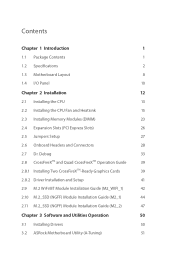
...Specifications 2 1.3 Motherboard Layout 8 1.4 I/O Panel 10 Chapter 2 Installation 12 2.1 Installing the CPU 13 2.2 Installing the CPU Fan and Heatsink 15 2.3 Installing Memory Modules (DIMM) 23 2.4 Expansion Slots (PCI Express Slots) 26 2.5 Jumpers Setup 27 2.6 Onboard Headers and Connectors 28 2.7 Dr. Debug 33 2.8 CrossFireXTM and Quad CrossFireXTM Operation Guide 39 2.8.1 Installing Two CrossFireXTM-Ready Graphics Cards 39 2.8.2 Driver Installation and Setup 41 2.9 M.2 WiFi/BT Module Installation Guide (M2_WIFI_1) 42 2.10 M.2_SSD (NGFF) Module Installation Guide...
...Specifications 2 1.3 Motherboard Layout 8 1.4 I/O Panel 10 Chapter 2 Installation 12 2.1 Installing the CPU 13 2.2 Installing the CPU Fan and Heatsink 15 2.3 Installing Memory Modules (DIMM) 23 2.4 Expansion Slots (PCI Express Slots) 26 2.5 Jumpers Setup 27 2.6 Onboard Headers and Connectors 28 2.7 Dr. Debug 33 2.8 CrossFireXTM and Quad CrossFireXTM Operation Guide 39 2.8.1 Installing Two CrossFireXTM-Ready Graphics Cards 39 2.8.2 Driver Installation and Setup 41 2.9 M.2 WiFi/BT Module Installation Guide (M2_WIFI_1) 42 2.10 M.2_SSD (NGFF) Module Installation Guide...
User Manual
Page 7
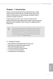
... the model you are using. ASRock website http://www.asrock.com. 1.1 Package Contents • ASRock B550 Steel Legend Motherboard (ATX Form Factor) • ASRock B550 Steel Legend Quick Installation Guide • ASRock B550 Steel Legend Support CD • 2 x Serial ATA (SATA) Data Cables (Optional) • 3 x Screws for M.2 Sockets (Optional) • 2 x Standoffs for purchasing ASRock B550 Steel Legend motherboard, a reliable motherboard produced under ASRock's consistently stringent quality control. In case any modifications of this documentation will be subject to change...
... the model you are using. ASRock website http://www.asrock.com. 1.1 Package Contents • ASRock B550 Steel Legend Motherboard (ATX Form Factor) • ASRock B550 Steel Legend Quick Installation Guide • ASRock B550 Steel Legend Support CD • 2 x Serial ATA (SATA) Data Cables (Optional) • 3 x Screws for M.2 Sockets (Optional) • 2 x Standoffs for purchasing ASRock B550 Steel Legend motherboard, a reliable motherboard produced under ASRock's consistently stringent quality control. In case any modifications of this documentation will be subject to change...

User Manual
Page 8
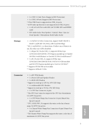
...; Gold Contact in DIMM Slots English 2 1.2 Specifications Platform • ATX Form Factor • 2oz Copper PCB CPU • Supports 3rd Gen AMD AM4 RyzenTM / future AMD RyzenTM Processors (3000 and 4000 Series Processors)* * Not compatible with AMD RyzenTM 5 3400G and RyzenTM 3 3200G. • Digi Power design • 14 Power Phase design Chipset • AMD B550 Memory • Dual Channel DDR4 Memory Technology • 4 x DDR4 DIMM Slots • AMD Ryzen series CPUs (Matisse) support DDR4 4733+ (OC...
...; Gold Contact in DIMM Slots English 2 1.2 Specifications Platform • ATX Form Factor • 2oz Copper PCB CPU • Supports 3rd Gen AMD AM4 RyzenTM / future AMD RyzenTM Processors (3000 and 4000 Series Processors)* * Not compatible with AMD RyzenTM 5 3400G and RyzenTM 3 3200G. • Digi Power design • 14 Power Phase design Chipset • AMD B550 Memory • Dual Channel DDR4 Memory Technology • 4 x DDR4 DIMM Slots • AMD Ryzen series CPUs (Matisse) support DDR4 4733+ (OC...

User Manual
Page 9
... boot disks • 2 x PCI Express 3.0 x1 Slots • Supports AMD Quad CrossFireXTM and CrossFireXTM • 1 x M.2 Socket (Key E), supports type 2230 WiFi/BT module • 15μ Gold Contact in VGA PCIe Slot (PCIE1) Graphics • Integrated AMD RadeonTM Vega Series Graphics in Ryzen Series APU* * Actual support may vary by independent display controllers • Supports HDMI 2.1 with max. resolution up to 5K (5120x2880)@120Hz • Supports Auto Lip Sync, Deep Color (12bpc), xvYCC and HBR (High Bit Rate Audio) with HDMI 2.1 Port...
... boot disks • 2 x PCI Express 3.0 x1 Slots • Supports AMD Quad CrossFireXTM and CrossFireXTM • 1 x M.2 Socket (Key E), supports type 2230 WiFi/BT module • 15μ Gold Contact in VGA PCIe Slot (PCIE1) Graphics • Integrated AMD RadeonTM Vega Series Graphics in Ryzen Series APU* * Actual support may vary by independent display controllers • Supports HDMI 2.1 with max. resolution up to 5K (5120x2880)@120Hz • Supports Auto Lip Sync, Deep Color (12bpc), xvYCC and HBR (High Bit Rate Audio) with HDMI 2.1 Port...
User Manual
Page 11
...) fan power. • 5 x Chassis/Water Pump Fan Connectors (4-pin) (Smart Fan Speed Control) * The Chassis/Water Pump Fan supports the water cooler fan of them is not supported on USB_34 ports. • 1 x RJ-45 LAN Port with LED (ACT/LINK LED and SPEED LED) • HD Audio Jacks: Rear Speaker / Central / Bass / Line in / Front Speaker / Microphone (Gold Audio Jacks) Storage • 6 x SATA3 6.0 Gb/s Connectors, support RAID (RAID 0, RAID 1 and RAID 10), NCQ, AHCI and Hot Plug* * M2_2 and SATA3_5_6 share lanes. B550 Steel Legend • 2 x USB 3.2 Gen1 Ports (Supports ESD...
...) fan power. • 5 x Chassis/Water Pump Fan Connectors (4-pin) (Smart Fan Speed Control) * The Chassis/Water Pump Fan supports the water cooler fan of them is not supported on USB_34 ports. • 1 x RJ-45 LAN Port with LED (ACT/LINK LED and SPEED LED) • HD Audio Jacks: Rear Speaker / Central / Bass / Line in / Front Speaker / Microphone (Gold Audio Jacks) Storage • 6 x SATA3 6.0 Gb/s Connectors, support RAID (RAID 0, RAID 1 and RAID 10), NCQ, AHCI and Hot Plug* * M2_2 and SATA3_5_6 share lanes. B550 Steel Legend • 2 x USB 3.2 Gen1 Ports (Supports ESD...

User Manual
Page 12
...Chassis/Water Pump Fans • Fan Multi-Speed Control: CPU, CPU/Water Pump, Chassis/ Water Pump Fans • Voltage monitoring: +12V, +5V, +3.3V, CPU Vcore, CPU VDDCR_SOC, DRAM, VPPM, CPU VDD 1.8V English 6 nector) • 1 x 8 pin 12V Power Connector (Hi-Density Power Connec- tor) • 2 x USB 2.0 Headers (Support 4 USB 2.0 ports) (Supports ESD Protection) • 1 x USB 3.2 Gen1 Header (Supports 2 USB 3.2 Gen1 ports) (Supports ESD Protection) • 1 x Front Panel Type C USB 3.2 Gen1 Header (Supports ESD Protection) • 1 x Dr. Debug with LED BIOS Feature • AMI UEFI...
...Chassis/Water Pump Fans • Fan Multi-Speed Control: CPU, CPU/Water Pump, Chassis/ Water Pump Fans • Voltage monitoring: +12V, +5V, +3.3V, CPU Vcore, CPU VDDCR_SOC, DRAM, VPPM, CPU VDD 1.8V English 6 nector) • 1 x 8 pin 12V Power Connector (Hi-Density Power Connec- tor) • 2 x USB 2.0 Headers (Support 4 USB 2.0 ports) (Supports ESD Protection) • 1 x USB 3.2 Gen1 Header (Supports 2 USB 3.2 Gen1 ports) (Supports ESD Protection) • 1 x Front Panel Type C USB 3.2 Gen1 Header (Supports ESD Protection) • 1 x Dr. Debug with LED BIOS Feature • AMI UEFI...

User Manual
Page 15
... Connector (SATA3_3) 17 SATA3 Connector (SATA3_5) 18 SATA3 Connector (SATA3_6) 19 SATA3 Connector (SATA3_4) 20 Clear CMOS Jumper (CLRCMOS1) 21 System Panel Header (PANEL1) 22 Power LED and Speaker Header (SPK_PLED1) 23 USB 2.0 Header (USB_7_8) 24 USB 2.0 Header (USB_5_6) 25 Chassis/Water Pump Fan Connector (CHA_FAN2/WP) 26 Chassis/Water Pump Fan Connector (CHA_FAN3/WP) 27 RGB LED Header (RGB_LED1) 28 Addressable LED Header (ADDR_LED1) 29 Front Panel Audio Header (HD_AUDIO1) 30 SPI TPM Header (SPI_TPM_J1) 31 Chassis/Water Pump Fan Connector (CHA_FAN1/WP) B550 Steel Legend...
... Connector (SATA3_3) 17 SATA3 Connector (SATA3_5) 18 SATA3 Connector (SATA3_6) 19 SATA3 Connector (SATA3_4) 20 Clear CMOS Jumper (CLRCMOS1) 21 System Panel Header (PANEL1) 22 Power LED and Speaker Header (SPK_PLED1) 23 USB 2.0 Header (USB_7_8) 24 USB 2.0 Header (USB_5_6) 25 Chassis/Water Pump Fan Connector (CHA_FAN2/WP) 26 Chassis/Water Pump Fan Connector (CHA_FAN3/WP) 27 RGB LED Header (RGB_LED1) 28 Addressable LED Header (ADDR_LED1) 29 Front Panel Audio Header (HD_AUDIO1) 30 SPI TPM Header (SPI_TPM_J1) 31 Chassis/Water Pump Fan Connector (CHA_FAN1/WP) B550 Steel Legend...

User Manual
Page 29
... DR 2667 SR/DR SR/DR SR/DR SR/DR 2667 English 23 B550 Steel Legend 2.3 Installing Memory Modules (DIMM) This motherboard provides four 288-pin DDR4 (Double Data Rate 4) DIMM slots, and supports Dual Channel Memory Technology. 1. For dual channel configuration, you install the memory modules on DDR4_A2 and DDR4_B2 first for better DRAM compatibility on 2 DIMMs configuration. It is unable to install identical (the same brand, speed, size and chip-type) DDR4 DIMM pairs. 2.
... DR 2667 SR/DR SR/DR SR/DR SR/DR 2667 English 23 B550 Steel Legend 2.3 Installing Memory Modules (DIMM) This motherboard provides four 288-pin DDR4 (Double Data Rate 4) DIMM slots, and supports Dual Channel Memory Technology. 1. For dual channel configuration, you install the memory modules on DDR4_A2 and DDR4_B2 first for better DRAM compatibility on 2 DIMMs configuration. It is unable to install identical (the same brand, speed, size and chip-type) DDR4 DIMM pairs. 2.

User Manual
Page 32
... supply is switched off or the power cord is used for PCI Express x4 lane width graphics cards. 2.4 Expansion Slots (PCI Express Slots) There are 4 PCI Express slots on the motherboard. PCIE2 (PCIe 3.0 x1 slot) is unplugged. PCIe Slot Configurations Ryzen series CPUs (Matisse): Single Graphics Card PCIE1 Gen4x16 Two Graphics Cards in CrossFireXTM Mode Gen4x16 PCIE3 N/A Gen3x4 Ryzen series APUs (Renoir): Single Graphics Card Two Graphics Cards in CrossFireXTM Mode PCIE1 Gen3x16 Gen3x16 PCIE3 N/A Gen3x4 English For a better thermal environment, please connect a chassis fan...
... supply is switched off or the power cord is used for PCI Express x4 lane width graphics cards. 2.4 Expansion Slots (PCI Express Slots) There are 4 PCI Express slots on the motherboard. PCIE2 (PCIe 3.0 x1 slot) is unplugged. PCIe Slot Configurations Ryzen series CPUs (Matisse): Single Graphics Card PCIE1 Gen4x16 Two Graphics Cards in CrossFireXTM Mode Gen4x16 PCIE3 N/A Gen3x4 Ryzen series APUs (Renoir): Single Graphics Card Two Graphics Cards in CrossFireXTM Mode PCIE1 Gen3x16 Gen3x16 PCIE3 N/A Gen3x4 English For a better thermal environment, please connect a chassis fan...

User Manual
Page 36
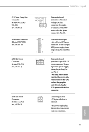
...see p.8, No. 3) 30 +12V This motherboard pro- Connect Mic_IN (MIC) to function correctly. Front Panel Audio Header (9-pin HD_AUDIO1) (see p.8, No. 29) GND PRESENCE# MIC_RET OUT_RET 1 OUT2_L J_SENSE OUT2_R MIC2_R MIC2_L This header is for connecting audio devices to Pin 1-3. 1 2 3 4 1 GND 2 FAN_VOLTAGE 3 CHA_FAN_SPEED 4 FAN_SPEED_CONTROL CPU Fan Connector (4-pin CPU_FAN1) (see p.8, No. 9) FAN_SPEED_CONTROL 4 CHA_FAN_SPEED 3 FAN_VOLTAGE 2 GND 1 GND FAN_VOLTAGE CHA_FAN_SPEED FAN_SPEED_CONTROL This motherboard provides five 4-Pin water cooling chassis fan connectors.
...see p.8, No. 3) 30 +12V This motherboard pro- Connect Mic_IN (MIC) to function correctly. Front Panel Audio Header (9-pin HD_AUDIO1) (see p.8, No. 29) GND PRESENCE# MIC_RET OUT_RET 1 OUT2_L J_SENSE OUT2_R MIC2_R MIC2_L This header is for connecting audio devices to Pin 1-3. 1 2 3 4 1 GND 2 FAN_VOLTAGE 3 CHA_FAN_SPEED 4 FAN_SPEED_CONTROL CPU Fan Connector (4-pin CPU_FAN1) (see p.8, No. 9) FAN_SPEED_CONTROL 4 CHA_FAN_SPEED 3 FAN_VOLTAGE 2 GND 1 GND FAN_VOLTAGE CHA_FAN_SPEED FAN_SPEED_CONTROL This motherboard provides five 4-Pin water cooling chassis fan connectors.
User Manual
Page 37
... graphics card. Do not plug the PCIe power cable to this connector in only one orientation. English 31 To use a 20-pin ATX power supply, please plug it along Pin 1 and Pin 5. *Warning: Please make sure that the power cable connected is optional. *The power supply plug fits into this connector. If you plan to Pin 1-3. 12 24 1 13 This motherboard provides a 24-pin ATX power connector. To use a 4-pin ATX power supply, please plug it to connect a 3-Pin CPU water cooler fan, please connect it along Pin 1 and Pin 13. 8 5 This motherboard...
... graphics card. Do not plug the PCIe power cable to this connector in only one orientation. English 31 To use a 20-pin ATX power supply, please plug it along Pin 1 and Pin 5. *Warning: Please make sure that the power cable connected is optional. *The power supply plug fits into this connector. If you plan to Pin 1-3. 12 24 1 13 This motherboard provides a 24-pin ATX power connector. To use a 4-pin ATX power supply, please plug it to connect a 3-Pin CPU water cooler fan, please connect it along Pin 1 and Pin 13. 8 5 This motherboard...
User Manual
Page 45
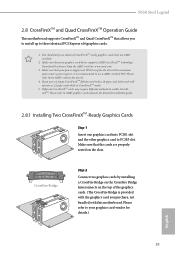
... the graphics cards. (The CrossFire Bridge is recommended to enable CrossFireXTM. Download the drivers from the AMD's website: www.amd.com 3. Different CrossFireXTM cards may require different methods to use a AMD certified PSU. CrossFire Bridge Step 2 Connect two graphics cards by installing a CrossFire Bridge on the CrossFire Bridge Interconnects on the slots. B550 Steel Legend 2.8 CrossFireXTM and Quad CrossFireXTM Operation Guide This motherboard supports CrossFireXTM and Quad CrossFireXTM that your power supply unit...
... the graphics cards. (The CrossFire Bridge is recommended to enable CrossFireXTM. Download the drivers from the AMD's website: www.amd.com 3. Different CrossFireXTM cards may require different methods to use a AMD certified PSU. CrossFire Bridge Step 2 Connect two graphics cards by installing a CrossFire Bridge on the CrossFire Bridge Interconnects on the slots. B550 Steel Legend 2.8 CrossFireXTM and Quad CrossFireXTM Operation Guide This motherboard supports CrossFireXTM and Quad CrossFireXTM that your power supply unit...
User Manual
Page 47
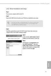
... graphics card and click Apply. Step 3 Install the required drivers and CATALYST Control Center then restart your computer and boot into OS. The Catalyst Uninstaller is an optional download. We recommend using this utility to your system. Then select Enable AMD CrossFireX and click Apply. English 41 Select the GPU number according to uninstall any VGA drivers installed in the Windows® system tray. B550 Steel Legend 2.8.2 Driver Installation and Setup Step 1 Power...
... graphics card and click Apply. Step 3 Install the required drivers and CATALYST Control Center then restart your computer and boot into OS. The Catalyst Uninstaller is an optional download. We recommend using this utility to your system. Then select Enable AMD CrossFireX and click Apply. English 41 Select the GPU number according to uninstall any VGA drivers installed in the Windows® system tray. B550 Steel Legend 2.8.2 Driver Installation and Setup Step 1 Power...
User Manual
Page 56
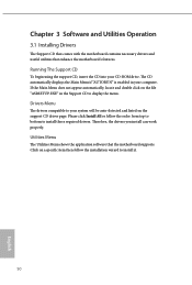
... system will be auto-detected and listed on the support CD driver page. If the Main Menu does not appear automatically, locate and double click on a specific item then follow the order from top to bottom to install it. 50 English Utilities Menu The Utilities Menu shows the application software that enhance the motherboard's features. Drivers Menu The drivers compatible to display the menu. Therefore, the drivers you install can work properly. Please click...
... system will be auto-detected and listed on the support CD driver page. If the Main Menu does not appear automatically, locate and double click on a specific item then follow the order from top to bottom to install it. 50 English Utilities Menu The Utilities Menu shows the application software that enhance the motherboard's features. Drivers Menu The drivers compatible to display the menu. Therefore, the drivers you install can work properly. Please click...
User Manual
Page 73
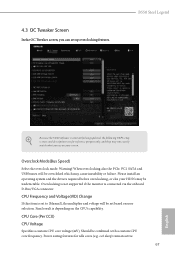
... updated, the following UEFI setup screens and descriptions are for idle cores (e.g. Power saving features for reference purpose only, and they may not exactly match what you can set based on user selection. B550 Steel Legend Because the UEFI software is set to [Manual], the multiplier and voltage will be undetectable. Overclocking is not supported if the monitor is depending on the CPU's capability. cc6 sleep) remain active. 67 English Please install...
... updated, the following UEFI setup screens and descriptions are for idle cores (e.g. Power saving features for reference purpose only, and they may not exactly match what you can set based on user selection. B550 Steel Legend Because the UEFI software is set to [Manual], the multiplier and voltage will be undetectable. Overclocking is not supported if the monitor is depending on the CPU's capability. cc6 sleep) remain active. 67 English Please install...

User Manual
Page 80
Onboard LAN Enable or disable the onboard network interface controller. PS2 Y-Cable Enable the PS2 Y-Cable or set this option to Auto. 74 English WAN Radio Configure the WiFi module's connectivity. BT On/Off Enable/disable the bluetooth.
Onboard LAN Enable or disable the onboard network interface controller. PS2 Y-Cable Enable the PS2 Y-Cable or set this option to Auto. 74 English WAN Radio Configure the WiFi module's connectivity. BT On/Off Enable/disable the bluetooth.


