

RAID Installation Guide
Page 2
... same model and capacity when creating a RAID set the option to RAID mode by using the onboard FastBuild BIOS utility under BIOS environment. After you make a SATA driver diskette, press or to enter BIOS setup to set . For optimal performance, please install identical drives of the data in the other drive if one logical unit. RAID 0 (Data Striping) RAID 0 is called data striping that copies and maintains an identical image of the "User Manual...
... same model and capacity when creating a RAID set the option to RAID mode by using the onboard FastBuild BIOS utility under BIOS environment. After you make a SATA driver diskette, press or to enter BIOS setup to set . For optimal performance, please install identical drives of the data in the other drive if one logical unit. RAID 0 (Data Striping) RAID 0 is called data striping that copies and maintains an identical image of the "User Manual...

RAID Installation Guide
Page 8
...Click to find the driver inside your USB flash disk. B. Please download the "SATA Floppy Imaged driver" from ASRock's website A. Insert the Support CD into your USB flash drive. 8 STEP 3.2: Download driver from ASRock's website and unzip the file into the DVD-ROM drive. Follow instructions to Tools Easy RAID Installer F. Please install the DVD-ROM. During system boot, press or key to finish the configuration. A. STEP 4: Windows installation A. B. C. Plug a USB drive into one of the USB port. STEP 3.1: Copy RAID driver to a USB flash drive You can choose...
...Click to find the driver inside your USB flash disk. B. Please download the "SATA Floppy Imaged driver" from ASRock's website A. Insert the Support CD into your USB flash drive. 8 STEP 3.2: Download driver from ASRock's website and unzip the file into the DVD-ROM drive. Follow instructions to Tools Easy RAID Installer F. Please install the DVD-ROM. During system boot, press or key to finish the configuration. A. STEP 4: Windows installation A. B. C. Plug a USB drive into one of the USB port. STEP 3.1: Copy RAID driver to a USB flash drive You can choose...

RAID Installation Guide
Page 10
I. J. After RAID driver is loaded, the RAID disk will show up. Select "AMD-RAID Config Device" and then click . Please follow Windows installation instruction to finish the process. 10 H.
I. J. After RAID driver is loaded, the RAID disk will show up. Select "AMD-RAID Config Device" and then click . Please follow Windows installation instruction to finish the process. 10 H.

RAID Installation Guide
Page 12
... system boot, press or key to Tools Easy RAID Installer F. STEP 2.2: Download driver from ASRock's website and unzip the file into your USB flash disk. 12 Go to enter UEFI setup utility. C. E. Insert the Support CD into one of the USB port. Click to save to finish the configuration. STEP 2.1: Copy RAID driver to a USB flash drive You can choose either STEP2.1 or STEP2.2 to exit. Please download the "SATA Floppy Imaged driver" from ASRock's website A. Plug a USB drive into the DVD-ROM drive...
... system boot, press or key to Tools Easy RAID Installer F. STEP 2.2: Download driver from ASRock's website and unzip the file into your USB flash disk. 12 Go to enter UEFI setup utility. C. E. Insert the Support CD into one of the USB port. Click to save to finish the configuration. STEP 2.1: Copy RAID driver to a USB flash drive You can choose either STEP2.1 or STEP2.2 to exit. Please download the "SATA Floppy Imaged driver" from ASRock's website A. Plug a USB drive into the DVD-ROM drive...

RAID Installation Guide
Page 13
For 64bit OS, the driver is under /AMD64 directly. STEP 3: Windows installation A. C. B. Please select the correct driver for your USB flash drive. During Windows installation process, when Disk selection page show up, please click . Select "AMD-RAID Bottom Device" and then click . 13 D. Click to find the driver inside your Windows version (Windows 10). For 32bit OS, the driver is under /I386 directory.
For 64bit OS, the driver is under /AMD64 directly. STEP 3: Windows installation A. C. B. Please select the correct driver for your USB flash drive. During Windows installation process, when Disk selection page show up, please click . Select "AMD-RAID Bottom Device" and then click . 13 D. Click to find the driver inside your Windows version (Windows 10). For 32bit OS, the driver is under /I386 directory.

User Manual
Page 4
... Introduction 1 1.1 Package Contents 1 1.2 Specifications 2 1.3 Motherboard Layout 6 1.4 I/O Panel 8 Chapter 2 Installation 10 2.1 Installing the CPU 11 2.2 Installing the CPU Fan and Heatsink 13 2.3 Installing Memory Modules (DIMM) 21 2.4 Expansion Slots (PCI Express Slots) 24 2.5 Jumpers Setup 25 2.6 Onboard Headers and Connectors 26 2.7 M.2_SSD (NGFF) Module Installation Guide 30 Chapter 3 Software and Utilities Operation 34 3.1 Installing Drivers 34 3.2 A-Tuning 35 3.2.1 Installing A-Tuning 35 3.2.2 Using A-Tuning 35 3.3 ASRock Live Update & APP Shop 38...
... Introduction 1 1.1 Package Contents 1 1.2 Specifications 2 1.3 Motherboard Layout 6 1.4 I/O Panel 8 Chapter 2 Installation 10 2.1 Installing the CPU 11 2.2 Installing the CPU Fan and Heatsink 13 2.3 Installing Memory Modules (DIMM) 21 2.4 Expansion Slots (PCI Express Slots) 24 2.5 Jumpers Setup 25 2.6 Onboard Headers and Connectors 26 2.7 M.2_SSD (NGFF) Module Installation Guide 30 Chapter 3 Software and Utilities Operation 34 3.1 Installing Drivers 34 3.2 A-Tuning 35 3.2.1 Installing A-Tuning 35 3.2.2 Using A-Tuning 35 3.3 ASRock Live Update & APP Shop 38...
User Manual
Page 6
...manual occur, the updated version will be available on ASRock's website as well. Chapter 3 contains the operation guide of the BIOS setup. ASRock website http://www.asrock.com. 1.1 Package Contents • ASRock B450M-HDV Motherboard (Micro ATX Form Factor) • ASRock B450M-HDV Quick Installation Guide • ASRock B450M-HDV Support CD • 2 x Serial ATA (SATA) Data Cables (Optional) • 1 x Screw for specific information about the model you are using. Chapter 4 contains the configuration guide of the software and utilities. If you for purchasing ASRock B450M-HDV...
...manual occur, the updated version will be available on ASRock's website as well. Chapter 3 contains the operation guide of the BIOS setup. ASRock website http://www.asrock.com. 1.1 Package Contents • ASRock B450M-HDV Motherboard (Micro ATX Form Factor) • ASRock B450M-HDV Quick Installation Guide • ASRock B450M-HDV Support CD • 2 x Serial ATA (SATA) Data Cables (Optional) • 1 x Screw for specific information about the model you are using. Chapter 4 contains the configuration guide of the software and utilities. If you for purchasing ASRock B450M-HDV...

User Manual
Page 8
...; Supports Energy Efficient Ethernet 802.3az • Supports PXE 3 English B450M-HDV Graphics Audio LAN AMD Ryzen series CPUs (Raven Ridge) • 1 x PCI Express 3.0 x16 Slot (PCIE2: x8 mode)* * Supports NVMe SSD as boot disks • 1 x PCI Express 2.0 x1 Slot • Integrated AMD RadeonTM Vega Series Graphics in Ryzen Series APU* * Actual support may vary by CPU • DirectX 12, Pixel Shader 5.0 • Max. shared memory 2GB • Three graphics output options: D-Sub, DVI-D and HDMI • Supports Triple Monitor • Supports HDMI with max.
...; Supports Energy Efficient Ethernet 802.3az • Supports PXE 3 English B450M-HDV Graphics Audio LAN AMD Ryzen series CPUs (Raven Ridge) • 1 x PCI Express 3.0 x16 Slot (PCIE2: x8 mode)* * Supports NVMe SSD as boot disks • 1 x PCI Express 2.0 x1 Slot • Integrated AMD RadeonTM Vega Series Graphics in Ryzen Series APU* * Actual support may vary by CPU • DirectX 12, Pixel Shader 5.0 • Max. shared memory 2GB • Three graphics output options: D-Sub, DVI-D and HDMI • Supports Triple Monitor • Supports HDMI with max.

User Manual
Page 9
...support RAID (RAID 0, RAID 1 and RAID 10), NCQ, AHCI and Hot Plug • 1 x Ultra M.2 Socket, supports M Key type 2242/2260/2280 M.2 SATA3 6.0 Gb/s module and M.2 PCI Express module up to Gen3 x4 (32 Gb/s) (with Summit Ridge, Raven Ridge and Pinnacle Ridge)* * Supports NVMe SSD as boot disks * Supports ASRock U.2 Kit Connector • 1 x Print Port Header • 1 x COM Port Header • 1 x TPM Header • 1 x Chassis Intrusion and Speaker Header • 1 x CPU Fan Connector (4-pin) * The CPU Fan Connector supports the CPU fan of maximum 1A (12W) fan power. • 1 x Chassis Fan...
...support RAID (RAID 0, RAID 1 and RAID 10), NCQ, AHCI and Hot Plug • 1 x Ultra M.2 Socket, supports M Key type 2242/2260/2280 M.2 SATA3 6.0 Gb/s module and M.2 PCI Express module up to Gen3 x4 (32 Gb/s) (with Summit Ridge, Raven Ridge and Pinnacle Ridge)* * Supports NVMe SSD as boot disks * Supports ASRock U.2 Kit Connector • 1 x Print Port Header • 1 x COM Port Header • 1 x TPM Header • 1 x Chassis Intrusion and Speaker Header • 1 x CPU Fan Connector (4-pin) * The CPU Fan Connector supports the CPU fan of maximum 1A (12W) fan power. • 1 x Chassis Fan...
User Manual
Page 10
...; Windows® 10 64-bit Certifications • FCC, CE • ErP/EuP ready (ErP/EuP ready power supply is required) * For detailed product information, please visit our website: http://www.asrock.com Please realize that there is in use. • 1 x 24 pin ATX Power Connector • 1 x 4 pin 12V Power Connector • 1 x Front Panel Audio Connector • 2 x USB 2.0 Headers (Support 4 USB 2.0 ports) (Supports ESD Protection) • 1 x USB 3.1 Gen1 Header (Supports 2 USB 3.1 Gen1 ports) (Supports ESD Protection) BIOS Feature • AMI UEFI...
...; Windows® 10 64-bit Certifications • FCC, CE • ErP/EuP ready (ErP/EuP ready power supply is required) * For detailed product information, please visit our website: http://www.asrock.com Please realize that there is in use. • 1 x 24 pin ATX Power Connector • 1 x 4 pin 12V Power Connector • 1 x Front Panel Audio Connector • 2 x USB 2.0 Headers (Support 4 USB 2.0 ports) (Supports ESD Protection) • 1 x USB 3.1 Gen1 Header (Supports 2 USB 3.1 Gen1 ports) (Supports ESD Protection) BIOS Feature • AMI UEFI...

User Manual
Page 11
1.3 Motherboard Layout PS2 Keyboard/ Mouse USB 2.0 T: USB1 B: USB2 ATX12V CPU_FAN1 RoHS DDR4_A1 (64 bit, 288-FpinSBmo8d0ul0e) DDR4_B1 (64 bit, 288-pin module) ATXPWR1 SOCKET AM4 HDMI1 USB 3.1 Gen1 T: USB1 B: USB2 RJ-45 LAN Top: LINE IN Center: FRONT Bottom: MIC IN USB 3.1 Gen1 T: USB3 B: USB4 CMOS Battery CHA_FAN1/WP 1 TPMS1 BIOS ROM B450M-HDV USB3_5_6 1 PCIE1 M2_1 LAN AUDIO CODEC HD_AUDIO1 1 1 COM1 PCIE2 Super I/O CLRCMOS1 1 LPT1 1 CHA_FAN2 SPK_CI1 1 PLED PWRBTN...
1.3 Motherboard Layout PS2 Keyboard/ Mouse USB 2.0 T: USB1 B: USB2 ATX12V CPU_FAN1 RoHS DDR4_A1 (64 bit, 288-FpinSBmo8d0ul0e) DDR4_B1 (64 bit, 288-pin module) ATXPWR1 SOCKET AM4 HDMI1 USB 3.1 Gen1 T: USB1 B: USB2 RJ-45 LAN Top: LINE IN Center: FRONT Bottom: MIC IN USB 3.1 Gen1 T: USB3 B: USB4 CMOS Battery CHA_FAN1/WP 1 TPMS1 BIOS ROM B450M-HDV USB3_5_6 1 PCIE1 M2_1 LAN AUDIO CODEC HD_AUDIO1 1 1 COM1 PCIE2 Super I/O CLRCMOS1 1 LPT1 1 CHA_FAN2 SPK_CI1 1 PLED PWRBTN...
User Manual
Page 12
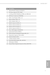
...12V Power Connector (ATX12V1) 2 CPU Fan Connector (CPU_FAN1) 3 2 x 288-pin DDR4 DIMM Slots (DDR4_A1, DDR4_B1) 4 ATX Power Connector (ATXPWR1) 5 USB 3.1 Gen1 Header (USB3_5_6) 6 USB 2.0 Header (USB_3_4) 7 USB 2.0 Header (USB_5_6) 8 SATA3 Connector (SATA3_3) 9 SATA3 Connector (SATA3_4) 10 SATA3 Connector (SATA3_1) 11 SATA3 Connector (SATA3_2) 12 Clear CMOS Jumper (CLRCMOS1) 13 System Panel Header (PANEL1) 14 Chassis Intrusion and Speaker Header (SPK_CI1) 15 Chassis Fan Connector (CHA_FAN2) 16 Print Port Header (LPT1) 17 COM Port Header (COM1) 18 Front Panel Audio Header (HD_AUDIO1) 19 TPM Header...
...12V Power Connector (ATX12V1) 2 CPU Fan Connector (CPU_FAN1) 3 2 x 288-pin DDR4 DIMM Slots (DDR4_A1, DDR4_B1) 4 ATX Power Connector (ATXPWR1) 5 USB 3.1 Gen1 Header (USB3_5_6) 6 USB 2.0 Header (USB_3_4) 7 USB 2.0 Header (USB_5_6) 8 SATA3 Connector (SATA3_3) 9 SATA3 Connector (SATA3_4) 10 SATA3 Connector (SATA3_1) 11 SATA3 Connector (SATA3_2) 12 Clear CMOS Jumper (CLRCMOS1) 13 System Panel Header (PANEL1) 14 Chassis Intrusion and Speaker Header (SPK_CI1) 15 Chassis Fan Connector (CHA_FAN2) 16 Print Port Header (LPT1) 17 COM Port Header (COM1) 18 Front Panel Audio Header (HD_AUDIO1) 19 TPM Header...
User Manual
Page 30
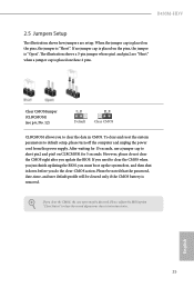
... cleared only if the CMOS battery is placed on these 2 pins. To clear and reset the system parameters to clear the record of previous chassis intrusion status. Please be noted that the password, date, time, and user default profile will be detected. B450M-HDV 2.5 Jumpers Setup The illustration shows how jumpers are "Short" when a jumper cap is placed on the pins, the jumper is "Open". After waiting for 15 seconds, use a jumper...
... cleared only if the CMOS battery is placed on these 2 pins. To clear and reset the system parameters to clear the record of previous chassis intrusion status. Please be noted that the password, date, time, and user default profile will be detected. B450M-HDV 2.5 Jumpers Setup The illustration shows how jumpers are "Short" when a jumper cap is placed on the pins, the jumper is "Open". After waiting for 15 seconds, use a jumper...

User Manual
Page 33
... a 4-Pin water 1 cooling chassis fan connector. 1. If you plan to connect a 3-Pin chassis water cooler fan, please connect it to OUT2_L. Chassis/Water Pump Fan Connector (4-pin CHA_FAN1/WP) (see p.6, No. 2) +12V CPU_FAN_SPEED GND FAN_SPEED_CONTROL 1 2 3 4 This motherboard provides a 4-Pin CPU fan (Quiet Fan) connector. English 28 Please follow the instructions in the Realtek Control panel and adjust "Recording Volume". D. High Definition Audio supports Jack Sensing, but the panel wire on the chassis must support HDA to MIC2_L. If you use...
... a 4-Pin water 1 cooling chassis fan connector. 1. If you plan to connect a 3-Pin chassis water cooler fan, please connect it to OUT2_L. Chassis/Water Pump Fan Connector (4-pin CHA_FAN1/WP) (see p.6, No. 2) +12V CPU_FAN_SPEED GND FAN_SPEED_CONTROL 1 2 3 4 This motherboard provides a 4-Pin CPU fan (Quiet Fan) connector. English 28 Please follow the instructions in the Realtek Control panel and adjust "Recording Volume". D. High Definition Audio supports Jack Sensing, but the panel wire on the chassis must support HDA to MIC2_L. If you use...

User Manual
Page 39
... Main Menu does not appear automatically, locate and double click on a specific item then follow the order from top to bottom to your CD-ROM drive. Utilities Menu The Utilities Menu shows the application software that enhance the motherboard's features. Chapter 3 Software and Utilities Operation 3.1 Installing Drivers The Support CD that comes with the motherboard contains necessary drivers and useful utilities that the motherboard supports. Therefore, the drivers you install can work properly. Click on the file...
... Main Menu does not appear automatically, locate and double click on a specific item then follow the order from top to bottom to your CD-ROM drive. Utilities Menu The Utilities Menu shows the application software that enhance the motherboard's features. Chapter 3 Software and Utilities Operation 3.1 Installing Drivers The Support CD that comes with the motherboard contains necessary drivers and useful utilities that the motherboard supports. Therefore, the drivers you install can work properly. Click on the file...

User Manual
Page 55
... reduce CPU voltage and memory frequency, and lead to enable or disable AMD CPU fTPM. Configuration options: [Enabled] and [Disabled]. AMD fTPM Switch Use this to system stability or compatibility issue with some memory modules or power supplies. SVM Mode When this option is set to [Enabled]. Configuration options: [Enabled] and [Disabled]. 50 English The default value is [Enabled]. If you install Windows® OS and want to enable this function, please set this item to enable or disable AMD's Cool 'n' QuietTM technology. The default value is [Enabled]. Please set...
... reduce CPU voltage and memory frequency, and lead to enable or disable AMD CPU fTPM. Configuration options: [Enabled] and [Disabled]. AMD fTPM Switch Use this to system stability or compatibility issue with some memory modules or power supplies. SVM Mode When this option is set to [Enabled]. Configuration options: [Enabled] and [Disabled]. 50 English The default value is [Enabled]. If you install Windows® OS and want to enable this function, please set this item to enable or disable AMD's Cool 'n' QuietTM technology. The default value is [Enabled]. Please set...

User Manual
Page 59
4.4.5 Super IO Configuration Serial Port Enable or disable the Serial port. Serial Port Address Select the address of the Parallel port. Parallel Port Enable or disable the Parallel port. PS2 Y-Cable Enable the PS2 Y-Cable or set this option to your connected device. Change Settings Select the address of the Serial port. Device Mode Select the device mode according to Auto. 54 English
4.4.5 Super IO Configuration Serial Port Enable or disable the Serial port. Serial Port Address Select the address of the Parallel port. Parallel Port Enable or disable the Parallel port. PS2 Y-Cable Enable the PS2 Y-Cable or set this option to your connected device. Change Settings Select the address of the Serial port. Device Mode Select the device mode according to Auto. 54 English

User Manual
Page 63
... on error Controls DF::PIEConfig[DisImmSyncFloodOnFatalError] Disabling this option has been used . SMTEN This item can be used to be used to remove any cores, a POWER CYCLE is the number of cores to disable symmetric multithreading. DF Common Options DRAM scrub time Provide a value that is required in order for this field are from 0x1 (1) - 0x10 (16). Warning: S3 is needed after selecting the 'Auto' option...
... on error Controls DF::PIEConfig[DisImmSyncFloodOnFatalError] Disabling this option has been used . SMTEN This item can be used to be used to remove any cores, a POWER CYCLE is the number of cores to disable symmetric multithreading. DF Common Options DRAM scrub time Provide a value that is required in order for this field are from 0x1 (1) - 0x10 (16). Warning: S3 is needed after selecting the 'Auto' option...

User Manual
Page 64
... enabled. Memory interleaving Controls fabric level memory interleaving (AUTO, none, channel, die, socket). The valid values are hashed during channel interleave mode. Memory interleaving size Controls the memory interleaving size. Memory Clear When this option's setting. System probe filter Controls whether or not the probe filter is fuse disabled. This determines the starting address of the interleave (bit 8, 9, 10 or 11). Note that channel, die, and socket has requirements on all dies. Channel interleaving hash Controls...
... enabled. Memory interleaving Controls fabric level memory interleaving (AUTO, none, channel, die, socket). The valid values are hashed during channel interleave mode. Memory interleaving size Controls the memory interleaving size. Memory Clear When this option's setting. System probe filter Controls whether or not the probe filter is fuse disabled. This determines the starting address of the interleave (bit 8, 9, 10 or 11). Note that channel, die, and socket has requirements on all dies. Channel interleaving hash Controls...

User Manual
Page 72
Network Configuration Use this to download the UEFI firmware. B450M-HDV Internet Setting Enable or disable sound effects in the setup utility. English 67 UEFI Download Server Select a server to configure internet connection settings for Internet Flash.
Network Configuration Use this to download the UEFI firmware. B450M-HDV Internet Setting Enable or disable sound effects in the setup utility. English 67 UEFI Download Server Select a server to configure internet connection settings for Internet Flash.


