
Intel Rapid Storage Guide
Page 12
..., press Ctrl and i at the same time to enter the option ROM user interface. 2. Enable RAID in System BIOS Use the instructions included with your motherboard to select the physical disks. 6. When finished press Enter. 12 Create a RAID Volume Use the following steps to RAID. 5. Enetr the Advanced menu. 3. The F6...
..., press Ctrl and i at the same time to enter the option ROM user interface. 2. Enable RAID in System BIOS Use the instructions included with your motherboard to select the physical disks. 6. When finished press Enter. 12 Create a RAID Volume Use the following steps to RAID. 5. Enetr the Advanced menu. 3. The F6...

RAID Installation Guide
Page 2
Please read the RAID configurations in this motherboard for internal storage devices. You may install SATA hard disks on SATA ports. 2 This section will guide you how to create RAID on this guide carefully according to SATA Hard Disks Installation 1.1 Serial ATA (SATA) Hard Disks Installation Intel chipset supports Serial ATA (SATA) hard disks with RAID functions, including RAID 0, RAID 1, RAID 5, RAID 10 and Intel Rapid Storage. 1. Guide to the Intel southbridge chipset that your motherboard adopts.
Please read the RAID configurations in this motherboard for internal storage devices. You may install SATA hard disks on SATA ports. 2 This section will guide you how to create RAID on this guide carefully according to SATA Hard Disks Installation 1.1 Serial ATA (SATA) Hard Disks Installation Intel chipset supports Serial ATA (SATA) hard disks with RAID functions, including RAID 0, RAID 1, RAID 5, RAID 10 and Intel Rapid Storage. 1. Guide to the Intel southbridge chipset that your motherboard adopts.

RAID Installation Guide
Page 3
... the data in parallel, interleaved stacks. This section will introduce the basic knowledge of RAID, and the guide to RAID Configurations 2.1 Introduction of RAID This motherboard adopts Intel southbridge chipset that copies and maintains an identical image of the RAID 0 Disk will double the data transfer rate of a single disk alone...
... the data in parallel, interleaved stacks. This section will introduce the basic knowledge of RAID, and the guide to RAID Configurations 2.1 Introduction of RAID This motherboard adopts Intel southbridge chipset that copies and maintains an identical image of the RAID 0 Disk will double the data transfer rate of a single disk alone...

RAID Installation Guide
Page 23
... than 2TB. STEP 1: Copy Intel® RAID drivers into a USB flash disk You can download the drivers from ASRock's website and unzip the files into a USB flash disk or copy the files from ASRock's motherboard support CD. (Please copy the files under the following directory: 32 bit: ..\i386\Win7_Intel.. 64-bit: ..\AMD64\Win7...
... than 2TB. STEP 1: Copy Intel® RAID drivers into a USB flash disk You can download the drivers from ASRock's website and unzip the files into a USB flash disk or copy the files from ASRock's motherboard support CD. (Please copy the files under the following directory: 32 bit: ..\i386\Win7_Intel.. 64-bit: ..\AMD64\Win7...

RAID Installation Guide
Page 25
... install this hotfix then reboot by itself. After installing Windows® 10 64-bit, install the hotfix kb2505454. (This may take more time to install motherboard drivers and utilities. 25
... install this hotfix then reboot by itself. After installing Windows® 10 64-bit, install the hotfix kb2505454. (This may take more time to install motherboard drivers and utilities. 25

Quick Installation Guide
Page 1
.... "Perchlorate Material-special handling may not be reproduced, transcribed, transmitted, or translated in any language, in this documentation, ASRock does not provide warranty of this documentation. This device complies with Part 15 of this documentation are used only for a ...advance. Products and corporate names appearing in Perchlorate Best Management Practices (BMP) regulations passed by ASRock. CALIFORNIA, USA ONLY The Lithium battery adopted on this motherboard contains Perchlorate, a toxic substance controlled in this documentation may or may apply, see www.dtsc...
.... "Perchlorate Material-special handling may not be reproduced, transcribed, transmitted, or translated in any language, in this documentation, ASRock does not provide warranty of this documentation. This device complies with Part 15 of this documentation are used only for a ...advance. Products and corporate names appearing in Perchlorate Best Management Practices (BMP) regulations passed by ASRock. CALIFORNIA, USA ONLY The Lithium battery adopted on this motherboard contains Perchlorate, a toxic substance controlled in this documentation may or may apply, see www.dtsc...
Quick Installation Guide
Page 3
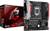
USB 2.0 T: USB1 B: USB2 PS2 Keyboard /Mouse Motherboard Layout 1 ATX12V1 RoHS B365M Phantom Gaming 4 2 34 5 CPU_FAN1 A_RGB_LED1 CPU_FAN2/ WP 6 1 HDMI1 Ultra M.2 PCIe Gen3 x4 DDR4_A1 (64 bit, 288-pin module) DDR4_A2 (64 bit, 288-pin ...45 CHA_FAN1/ WP Top: 8 M2_1 USB3_5_6 Central/Bass LINE IN Center: REAR SPK Bottom: Optical SPDIF Top: Center: FRONT Bottom: MIC IN LAN PCIE1 26 B365M Phantom Gaming 4 1 9 1 RGB_LED2 M2_2 SATA3_2_3 PCIE2 Intel 10 SATA3_4_5 CMOS B365 11 Battery CT1 M2_3 AUDIO CODEC HD_AUDIO1 1 PCIE3 COM1 CLRMOS1 RGB_LED1 1 1 1 TPMS1...
USB 2.0 T: USB1 B: USB2 PS2 Keyboard /Mouse Motherboard Layout 1 ATX12V1 RoHS B365M Phantom Gaming 4 2 34 5 CPU_FAN1 A_RGB_LED1 CPU_FAN2/ WP 6 1 HDMI1 Ultra M.2 PCIe Gen3 x4 DDR4_A1 (64 bit, 288-pin module) DDR4_A2 (64 bit, 288-pin ...45 CHA_FAN1/ WP Top: 8 M2_1 USB3_5_6 Central/Bass LINE IN Center: REAR SPK Bottom: Optical SPDIF Top: Center: FRONT Bottom: MIC IN LAN PCIE1 26 B365M Phantom Gaming 4 1 9 1 RGB_LED2 M2_2 SATA3_2_3 PCIE2 Intel 10 SATA3_4_5 CMOS B365 11 Battery CT1 M2_3 AUDIO CODEC HD_AUDIO1 1 PCIE3 COM1 CLRMOS1 RGB_LED1 1 1 1 TPMS1...
Quick Installation Guide
Page 7
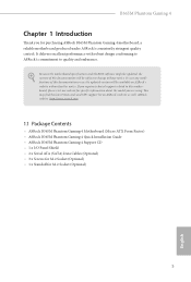
...://www.asrock.com. 1.1 Package Contents • ASRock B365M Phantom Gaming 4 Motherboard (Micro ATX Form Factor) • ASRock B365M Phantom Gaming 4 Quick Installation Guide • ASRock B365M Phantom Gaming 4 Support CD • 1 x I/O Panel Shield • 2 x Serial ATA (SATA) Data Cables (Optional) • 3 x Screws for M.2 Socket (Optional) • 1 x Standoff for specific information about the model you are using. If you for purchasing ASRock B365M Phantom Gaming 4 motherboard, a reliable motherboard produced under ASRock's consistently...
...://www.asrock.com. 1.1 Package Contents • ASRock B365M Phantom Gaming 4 Motherboard (Micro ATX Form Factor) • ASRock B365M Phantom Gaming 4 Quick Installation Guide • ASRock B365M Phantom Gaming 4 Support CD • 1 x I/O Panel Shield • 2 x Serial ATA (SATA) Data Cables (Optional) • 3 x Screws for M.2 Socket (Optional) • 1 x Standoff for specific information about the model you are using. If you for purchasing ASRock B365M Phantom Gaming 4 motherboard, a reliable motherboard produced under ASRock's consistently...

Quick Installation Guide
Page 13
... them on a carpet. Failure to ensure that the motherboard fits into it. Doing so may cause physical injuries and damages to motherboard components. • In order to avoid damage from static electricity to the motherboard's components, NEVER place your chassis to do not overtighten the screws! B365M Phantom Gaming 4 Chapter 2 Installation This is a Micro ATX form...
... them on a carpet. Failure to ensure that the motherboard fits into it. Doing so may cause physical injuries and damages to motherboard components. • In order to avoid damage from static electricity to the motherboard's components, NEVER place your chassis to do not overtighten the screws! B365M Phantom Gaming 4 Chapter 2 Installation This is a Micro ATX form...

Quick Installation Guide
Page 16
Please save and replace the cover if the processor is removed. The cover must be placed if you wish to return the motherboard for after service. 14 English
Please save and replace the cover if the processor is removed. The cover must be placed if you wish to return the motherboard for after service. 14 English

Quick Installation Guide
Page 18
... memory module into the slot at incorrect orientation. For dual channel configuration, you always need to the motherboard and the DIMM if you force the DIMM into a DDR4 slot; otherwise, this motherboard and DIMM may be damaged. It will cause permanent damage to install identical (the same brand, speed... DDR4_B1 Populated DDR4_B2 Populated Populated The DIMM only fits in one or three memory module installed. 3. 2.3 Installing Memory Modules (DIMM) This motherboard provides four 288-pin DDR4 (Double Data Rate 4) DIMM slots, and supports Dual Channel Memory Technology. 1.
... memory module into the slot at incorrect orientation. For dual channel configuration, you always need to the motherboard and the DIMM if you force the DIMM into a DDR4 slot; otherwise, this motherboard and DIMM may be damaged. It will cause permanent damage to install identical (the same brand, speed... DDR4_B1 Populated DDR4_B2 Populated Populated The DIMM only fits in one or three memory module installed. 3. 2.3 Installing Memory Modules (DIMM) This motherboard provides four 288-pin DDR4 (Double Data Rate 4) DIMM slots, and supports Dual Channel Memory Technology. 1.

Quick Installation Guide
Page 20
... Configurations Single Graphics Card Two Graphics Cards in CrossFireXTM Mode PCIE1 x16 x16 PCIE3 N/A x4 For a better thermal environment, please connect a chassis fan to the motherboard's chassis fan connector (CHA_FAN1/WP, CHA_FAN2/WP or CHA_FAN3/WP) when using multiple graphics cards. English 18 PCIe slots: PCIE1 (PCIe 3.0 x16 slot) is used... card, please make necessary hardware settings for PCI Express x1 lane width cards. 2.4 Expansion Slots (PCI Express Slots) There are 3 PCI Express slots on the motherboard.
... Configurations Single Graphics Card Two Graphics Cards in CrossFireXTM Mode PCIE1 x16 x16 PCIE3 N/A x4 For a better thermal environment, please connect a chassis fan to the motherboard's chassis fan connector (CHA_FAN1/WP, CHA_FAN2/WP or CHA_FAN3/WP) when using multiple graphics cards. English 18 PCIe slots: PCIE1 (PCIe 3.0 x16 slot) is used... card, please make necessary hardware settings for PCI Express x1 lane width cards. 2.4 Expansion Slots (PCI Express Slots) There are 3 PCI Express slots on the motherboard.

Quick Installation Guide
Page 22
... status indicator on the chassis front panel. When connecting your system using the power button. The front panel design may configure the way to the motherboard. The LED is on the chassis to this header, make sure the wire assignments and the pin assignments are NOT jumpers. 2.6 Onboard Headers and Connectors...
... status indicator on the chassis front panel. When connecting your system using the power button. The front panel design may configure the way to the motherboard. The LED is on the chassis to this header, make sure the wire assignments and the pin assignments are NOT jumpers. 2.6 Onboard Headers and Connectors...

Quick Installation Guide
Page 23
... PLED+ PLED+ PLED- English 21 B365M Phantom Gaming 4 Power LED and Speaker Header (7-pin SPK_PLED1) (see p.1, No. 11) SATA3_1 SATA3_0 SATA3_4 SATA3_2 SATA3_5 SATA3_3 These six SATA3 connectors support SATA data cables for internal storage devices with up to this motherboard. This USB 3.1 Gen1 header can ...support two ports. USB 3.1 Gen1 Header (19-pin USB3_5_6) (see p.1, No. 17) USB_PWR PP+ GND DUMMY 1 GND P+ PUSB_PWR There are two headers on this motherboard.
... PLED+ PLED+ PLED- English 21 B365M Phantom Gaming 4 Power LED and Speaker Header (7-pin SPK_PLED1) (see p.1, No. 11) SATA3_1 SATA3_0 SATA3_4 SATA3_2 SATA3_5 SATA3_3 These six SATA3 connectors support SATA data cables for internal storage devices with up to this motherboard. This USB 3.1 Gen1 header can ...support two ports. USB 3.1 Gen1 Header (19-pin USB3_5_6) (see p.1, No. 17) USB_PWR PP+ GND DUMMY 1 GND P+ PUSB_PWR There are two headers on this motherboard.

Quick Installation Guide
Page 24
...need to Ground (GND). FAN_SPEED_CONTROL CHA_FAN_SPEED FAN_VOLTAGE GND CPU Fan Connector (4-pin CPU_FAN1) (see p.1, No. 20) 1 GND This motherboard 2 3 FAN_VOLTAGE CHA_FAN_SPEED provides three 4-Pin water 4 FAN_SPEED_CONTROL cooling chassis fan connectors. Chassis/Water Pump Fan Connectors (4-pin CHA_FAN1/WP).../WP) (see p.1, No. 19) (4-pin CHA_FAN3/WP) (see p.1, No. 2) FAN_SPEED_CONTROL CPU_FAN_SPEED FAN_VOLTAGE GND 1 2 34 This motherboard provides a 4-Pin CPU fan (Quiet Fan) connector. Please follow the instructions in the Realtek Control panel and adjust "Recording Volume"....
...need to Ground (GND). FAN_SPEED_CONTROL CHA_FAN_SPEED FAN_VOLTAGE GND CPU Fan Connector (4-pin CPU_FAN1) (see p.1, No. 20) 1 GND This motherboard 2 3 FAN_VOLTAGE CHA_FAN_SPEED provides three 4-Pin water 4 FAN_SPEED_CONTROL cooling chassis fan connectors. Chassis/Water Pump Fan Connectors (4-pin CHA_FAN1/WP).../WP) (see p.1, No. 19) (4-pin CHA_FAN3/WP) (see p.1, No. 2) FAN_SPEED_CONTROL CPU_FAN_SPEED FAN_VOLTAGE GND 1 2 34 This motherboard provides a 4-Pin CPU fan (Quiet Fan) connector. Please follow the instructions in the Realtek Control panel and adjust "Recording Volume"....

Quick Installation Guide
Page 25
... security, protects digital identities, and ensures platform integrity. English 23 This COM1 header supports a serial port module. This motherboard provides a 24-pin ATX power connector. B365M Phantom Gaming 4 CPU/Water Pump Fan Connector (4-pin CPU_FAN2/WP) (see p.1, No. 5) FAN_SPEED_CONTROL CPU_FAN_SPEED FAN_VOLTAGE GND 1 2 ...Trusted Platform Module (TPM) system, 1 which can securely store keys, digital certificates, passwords, and data. This motherboard provides an 8-pin ATX 12V power connector. If you plan to connect a 3-Pin CPU water cooler fan, please connect it to Pin 1-3....
... security, protects digital identities, and ensures platform integrity. English 23 This COM1 header supports a serial port module. This motherboard provides a 24-pin ATX power connector. B365M Phantom Gaming 4 CPU/Water Pump Fan Connector (4-pin CPU_FAN2/WP) (see p.1, No. 5) FAN_SPEED_CONTROL CPU_FAN_SPEED FAN_VOLTAGE GND 1 2 ...Trusted Platform Module (TPM) system, 1 which can securely store keys, digital certificates, passwords, and data. This motherboard provides an 8-pin ATX 12V power connector. If you plan to connect a 3-Pin CPU water cooler fan, please connect it to Pin 1-3....

Quick Installation Guide
Page 31
... Step 4 Prepare the M.2 standoff that the M.2 (NGFF) SSD module only fits in one orientation. 1 2 1 B365M Phantom Gaming 4 Step 3 Before installing a M.2 (NGFF) SSD module, please loosen the screws to secure the module into the desired nut location on the motherboard. Then hand tighten the standoff into place. Please be aware that comes with a screwdriver to...
... Step 4 Prepare the M.2 standoff that the M.2 (NGFF) SSD module only fits in one orientation. 1 2 1 B365M Phantom Gaming 4 Step 3 Before installing a M.2 (NGFF) SSD module, please loosen the screws to secure the module into the desired nut location on the motherboard. Then hand tighten the standoff into place. Please be aware that comes with a screwdriver to...

Quick Installation Guide
Page 34
... on the module type and length. Please do not overtighten the screw as this might damage the module. D C B A D C B A D C B A Step 3 Move the standoff based on the motherboard. Please be used. English D C B A 20o D C NUT2 NUT1 32 Step 6 Tighten the screw with a screwdriver to secure the module into the M.2 slot. Otherwise, release the standoff...
... on the module type and length. Please do not overtighten the screw as this might damage the module. D C B A D C B A D C B A Step 3 Move the standoff based on the motherboard. Please be used. English D C B A 20o D C NUT2 NUT1 32 Step 6 Tighten the screw with a screwdriver to secure the module into the M.2 slot. Otherwise, release the standoff...
Quick Installation Guide
Page 37
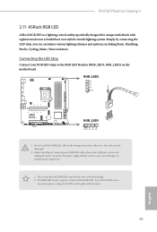
... orientation; The RGB LED header supports standard 5050 RGB LED strip (12V/G/R/B), with sophisticated tastes to the RGB LED Headers (RGB_LED1, RGB_LED2) on the motherboard. B365M Phantom Gaming 4 2.11 ASRock RGB LED ASRock RGB LED is a lighting control utility specifically designed for unique individuals with a maximum power rating of 3A (12V) and length within 2 meters. RGB_LED2...
... orientation; The RGB LED header supports standard 5050 RGB LED strip (12V/G/R/B), with sophisticated tastes to the RGB LED Headers (RGB_LED1, RGB_LED2) on the motherboard. B365M Phantom Gaming 4 2.11 ASRock RGB LED ASRock RGB LED is a lighting control utility specifically designed for unique individuals with a maximum power rating of 3A (12V) and length within 2 meters. RGB_LED2...

Quick Installation Guide
Page 38
ADDR_LED1 GND DO_ADDR VOUT 1 B365M Phantom Gaming 4 1 1. Before installing or removing your RGB LED cable, please power off your Addressable RGB LED strip to the Addressable LED Header (ADDR_LED1) on the motherboard. Never install the RGB LED cable in the wrong orientation; Please note that the RGB LED ...so may be damaged. 2. The RGB LED header supports WS2812B addressable RGB LED strip (5V/Data/ GND), with the package. 2. Failure to motherboard components. 1. otherwise, the cable may cause damages to do not come with a maximum power rating of 3A (5V) and length within 2...
ADDR_LED1 GND DO_ADDR VOUT 1 B365M Phantom Gaming 4 1 1. Before installing or removing your RGB LED cable, please power off your Addressable RGB LED strip to the Addressable LED Header (ADDR_LED1) on the motherboard. Never install the RGB LED cable in the wrong orientation; Please note that the RGB LED ...so may be damaged. 2. The RGB LED header supports WS2812B addressable RGB LED strip (5V/Data/ GND), with the package. 2. Failure to motherboard components. 1. otherwise, the cable may cause damages to do not come with a maximum power rating of 3A (5V) and length within 2...


