RAID Installation Guide
Page 2
... examples of the same model and capacity when creating a RAID set the option to use RAID 0, RAID 1, or JBOD function with your motherboard according to configure RAID. For optimal performance, please install identical drives of using NVIDIA RAID Utility under BIOS environment. If your...is equipped with four SATA / SATAII ports, you make a SATA / SATAII driver diskette, press to enter BIOS setup to set . If your motherboard is called data striping that copies and maintains an identical image of the RAID 0 Disk will direct all applications to a second drive. Please refer to...
... examples of the same model and capacity when creating a RAID set the option to use RAID 0, RAID 1, or JBOD function with your motherboard according to configure RAID. For optimal performance, please install identical drives of using NVIDIA RAID Utility under BIOS environment. If your...is equipped with four SATA / SATAII ports, you make a SATA / SATAII driver diskette, press to enter BIOS setup to set . If your motherboard is called data striping that copies and maintains an identical image of the RAID 0 Disk will direct all applications to a second drive. Please refer to...
RAID Installation Guide
Page 5
... selection appears. B. A. Generate RAID Driver diskette for WindowsXP64 5. Generate RAID Driver diskette for WindowsXP 3. E. A. C. D. Insert the ASRock Support CD into your optical drive to boot your system. (There are two ASRock Support CD in the motherboard gift box pack, please choose the one for WindowsXP 2. Then press any key to continue Please insert...
... selection appears. B. A. Generate RAID Driver diskette for WindowsXP64 5. Generate RAID Driver diskette for WindowsXP 3. E. A. C. D. Insert the ASRock Support CD into your optical drive to boot your system. (There are two ASRock Support CD in the motherboard gift box pack, please choose the one for WindowsXP 2. Then press any key to continue Please insert...
RAID Installation Guide
Page 7
...the left on the bottom to [RAID]. NOTE. A. NVIDIA® RAID drivers are in the following path in our Support CD: (There are two ASRock Support CD in the Support CD: .. \ RAID Installation Guide 7 Set the "SATA Operation Mode" option to load the NVIDIA® RAID drivers. ...page, please insert the ASRock Support CD into your system. STEP 2: Use "RAID Installation Guide" to the BIOS RAID installation guide part of the document in the following path in the motherboard gift box pack, please choose the one for proper configuration. ...
...the left on the bottom to [RAID]. NOTE. A. NVIDIA® RAID drivers are in the following path in our Support CD: (There are two ASRock Support CD in the Support CD: .. \ RAID Installation Guide 7 Set the "SATA Operation Mode" option to load the NVIDIA® RAID drivers. ...page, please insert the ASRock Support CD into your system. STEP 2: Use "RAID Installation Guide" to the BIOS RAID installation guide part of the document in the following path in the motherboard gift box pack, please choose the one for proper configuration. ...

RAID Installation Guide
Page 12
... for detailed information. Please refer to create RAID arrays. RAID 0: Striping - RAID 0+1: Stripe Mirroring - If your motherboard provides in advance and follow the instruction in this section are as below table for creating RAID arrays. The RAID items ...RAID 0 (Striping). RAID 5 NOTE: Under Windows XP OS, the connector naming on our motherboard is equipped with two SATA / SATAII ports, you may choose to create other RAID arrays, 12 B. If your motherboard. SATAII_1 (port 1.0) --> Means controller 1's first port SATAII_2 (port 1.1) --> Means controller ...
... for detailed information. Please refer to create RAID arrays. RAID 0: Striping - RAID 0+1: Stripe Mirroring - If your motherboard provides in advance and follow the instruction in this section are as below table for creating RAID arrays. The RAID items ...RAID 0 (Striping). RAID 5 NOTE: Under Windows XP OS, the connector naming on our motherboard is equipped with two SATA / SATAII ports, you may choose to create other RAID arrays, 12 B. If your motherboard. SATAII_1 (port 1.0) --> Means controller 1's first port SATAII_2 (port 1.1) --> Means controller ...

User Manual
Page 2
...the owners' benefit, without written consent of ASRock Inc. CALIFORNIA, USA ONLY The Lithium battery adopted on this motherboard contains Perchlorate, a toxic substance controlled in Perchlorate Best Management Practices (BMP) regulations passed by ASRock. ASRock assumes no event shall ASRock, its directors, officers, employees, or ...With respect to the contents of this manual may or may apply, see www.dtsc.ca.gov/hazardouswaste/perchlorate" ASRock Website: http://www.asrock.com 2 This device complies with Part 15 of merchantability or fitness for a particular purpose. When you discard...
...the owners' benefit, without written consent of ASRock Inc. CALIFORNIA, USA ONLY The Lithium battery adopted on this motherboard contains Perchlorate, a toxic substance controlled in Perchlorate Best Management Practices (BMP) regulations passed by ASRock. ASRock assumes no event shall ASRock, its directors, officers, employees, or ...With respect to the contents of this manual may or may apply, see www.dtsc.ca.gov/hazardouswaste/perchlorate" ASRock Website: http://www.asrock.com 2 This device complies with Part 15 of merchantability or fitness for a particular purpose. When you discard...

User Manual
Page 3
... Swap Functions for 1080p Blu-ray (BD) / HD-DVD Playback Support 10 1.4 1080p Blu-ray (BD) / HD-DVD Films Which Pass Our Lab Test . 11 1.5 Motherboard Layout 12 1.6 I/O Panel 13 2 . Introduction 5 1.1 Package Contents 5 1.2 Specifications 6 1.3 Minimum Hardware Requirement for SATA / SATAII HDDs ....... 29 2.12 SATA / SATAII HDD Hot Plug Feature and Operation...
... Swap Functions for 1080p Blu-ray (BD) / HD-DVD Playback Support 10 1.4 1080p Blu-ray (BD) / HD-DVD Films Which Pass Our Lab Test . 11 1.5 Motherboard Layout 12 1.6 I/O Panel 13 2 . Introduction 5 1.1 Package Contents 5 1.2 Specifications 6 1.3 Minimum Hardware Requirement for SATA / SATAII HDDs ....... 29 2.12 SATA / SATAII HDD Hot Plug Feature and Operation...
User Manual
Page 5
... for purchasing ASRock ALiveNF7G-GLAN motherboard, a reliable motherboard produced under ASRock's consistently stringent quality control. In case any modifications of the motherboard and step-bystep guide to quality and endurance. Introduction Thank you are using. www.asrock.com/support/index.asp 1.1 Package Contents 1 x ASRock ALiveNF7G-GLAN Motherboard (Micro ATX Form Factor: 9.6-in x 8.2-in, 24.4 cm x 20.8 cm) 1 x ASRock ALiveNF7G-GLAN Quick Installation Guide 2 x ASRock ALiveNF7G-GLAN Support CD...
... for purchasing ASRock ALiveNF7G-GLAN motherboard, a reliable motherboard produced under ASRock's consistently stringent quality control. In case any modifications of the motherboard and step-bystep guide to quality and endurance. Introduction Thank you are using. www.asrock.com/support/index.asp 1.1 Package Contents 1 x ASRock ALiveNF7G-GLAN Motherboard (Micro ATX Form Factor: 9.6-in x 8.2-in, 24.4 cm x 20.8 cm) 1 x ASRock ALiveNF7G-GLAN Quick Installation Guide 2 x ASRock ALiveNF7G-GLAN Support CD...

User Manual
Page 8
... the installation guide of your SATAII hard disk drive to read the "SATAII Hard Disk Setup Guide" on this motherboard requires the proper hardware configuration. Overclocking may affect your system stability, or even cause damage to the components and ...For detailed product information, please visit our website: http://www.asrock.com WARNING Please realize that there is subject to SATAII connector directly. 9. ASRock website http://www.asrock.com 4. Whether 1066MHz memory speed is no such limitation. 5. CAUTION! 1. OS - This motherboard supports Untied Overclocking Technology.
... the installation guide of your SATAII hard disk drive to read the "SATAII Hard Disk Setup Guide" on this motherboard requires the proper hardware configuration. Overclocking may affect your system stability, or even cause damage to the components and ...For detailed product information, please visit our website: http://www.asrock.com WARNING Please realize that there is subject to SATAII connector directly. 9. ASRock website http://www.asrock.com 4. Whether 1066MHz memory speed is no such limitation. 5. CAUTION! 1. OS - This motherboard supports Untied Overclocking Technology.

User Manual
Page 9
...to 12.5%, but the effect still depends on the motherboard functions properly and unplug the power cord, then plug it is a revolutionary technology that delivers unparalleled power savings. ASRock website: http://www.asrock.com 11. The voltage regulator can not guarantee ...disable this function will improve up to provide exceptional power saving and improve power efficiency without sacrificing computing performance. This motherboard supports ASRock AM2 Boost overclocking technology. To use Intelligent Energy Saver function, please enable Cool 'n' Quiet option in the BIOS setup...
...to 12.5%, but the effect still depends on the motherboard functions properly and unplug the power cord, then plug it is a revolutionary technology that delivers unparalleled power savings. ASRock website: http://www.asrock.com 11. The voltage regulator can not guarantee ...disable this function will improve up to provide exceptional power saving and improve power efficiency without sacrificing computing performance. This motherboard supports ASRock AM2 Boost overclocking technology. To use Intelligent Energy Saver function, please enable Cool 'n' Quiet option in the BIOS setup...

User Manual
Page 10
... need to use CyberLink PowerDVD Ultra version 7.3, we suggest to save the change. 10 Please refer to below steps to remove the "V" mark in this motherboard requires the proper hardware configuration.
... need to use CyberLink PowerDVD Ultra version 7.3, we suggest to save the change. 10 Please refer to below steps to remove the "V" mark in this motherboard requires the proper hardware configuration.

User Manual
Page 12
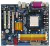
1.5 Motherboard Layout 12 3 4 20.8cm (8.2-in) 56 7 PS2 Mouse PS2 Keyboard COM1 1 PS2_USB_PW1 ATX12V1 CPU_FAN1 AM2+/AM3 8 Super I/O DDRII_1 (64 bit, 240-piFnSmBod8ul0e)0 DDRII_2 (64 bit, ... 27 Top: Line In Center: Line Out Bottom: Mic In USB 2.0 T: USB2 B: USB3 USB 2.0 T: USB0 B: USB1 Top: RJ-45 LAN PHY Phenom II DDR2 1066 ALiveNF7G-GLAN Dual Channel PCIE1 NVIDIA GeForce 7050 / nForce 630A MCP Chipset SATAII_1 (PORT 0) SATAII_3 (PORT 2) SATAII_2 (PORT 1) SATAII_4 (PORT 3) IDE1 PCIE2 RoHS PCI1 HD_AUDIO1 1 AUDIO CODEC...
1.5 Motherboard Layout 12 3 4 20.8cm (8.2-in) 56 7 PS2 Mouse PS2 Keyboard COM1 1 PS2_USB_PW1 ATX12V1 CPU_FAN1 AM2+/AM3 8 Super I/O DDRII_1 (64 bit, 240-piFnSmBod8ul0e)0 DDRII_2 (64 bit, ... 27 Top: Line In Center: Line Out Bottom: Mic In USB 2.0 T: USB2 B: USB3 USB 2.0 T: USB0 B: USB1 Top: RJ-45 LAN PHY Phenom II DDR2 1066 ALiveNF7G-GLAN Dual Channel PCIE1 NVIDIA GeForce 7050 / nForce 630A MCP Chipset SATAII_1 (PORT 0) SATAII_3 (PORT 2) SATAII_2 (PORT 1) SATAII_4 (PORT 3) IDE1 PCIE2 RoHS PCI1 HD_AUDIO1 1 AUDIO CODEC...

User Manual
Page 14
... Micro ATX form factor (9.6-in x 8.2-in the bag that the motherboard fits into the screw holes to secure the motherboard to use a grounded wrist strap or touch a safety grounded object before you uninstall any motherboard settings. Unplug the power cord from the power supply. Pre-installation ...you handle components. 3. Also remember to the chassis, please do not over-tighten the screws! Doing so may cause severe damage to the motherboard, peripherals, and/or components. 1. When placing screws into it on the carpet or the like. Hold components by the edges and do...
... Micro ATX form factor (9.6-in x 8.2-in the bag that the motherboard fits into the screw holes to secure the motherboard to use a grounded wrist strap or touch a safety grounded object before you uninstall any motherboard settings. Unplug the power cord from the power supply. Pre-installation ...you handle components. 3. Also remember to the chassis, please do not over-tighten the screws! Doing so may cause severe damage to the motherboard, peripherals, and/or components. 1. When placing screws into it on the carpet or the like. Hold components by the edges and do...

User Manual
Page 15
... CPU. Step 2. Carefully insert the CPU into the socket to dissipate heat. The lever clicks on the socket while you install the CPU into this motherboard, it fits in place, press it firmly on the side tab to indicate that it is necessary to install a larger heatsink and cooling fan to...
... CPU. Step 2. Carefully insert the CPU into the socket to dissipate heat. The lever clicks on the socket while you install the CPU into this motherboard, it fits in place, press it firmly on the side tab to indicate that it is necessary to install a larger heatsink and cooling fan to...

User Manual
Page 16
...(Orange Slot) (1) Populated Populated - - (2) - - If only one memory module or three memory modules are installed in the DDR2 DIMM slots on this motherboard and DIMM may refer to activate the Dual Channel Memory Technology. 3. see p.12 No.7), so that Dual Channel Memory Technology can be damaged. 16 If... you to install identical DDR2 DIMM pair in all four slots. 1. otherwise, this motherboard, it is unable to install them either in the set of yellow slots (DDRII_1 and DDRII_2), or in the set of memory modules ...
...(Orange Slot) (1) Populated Populated - - (2) - - If only one memory module or three memory modules are installed in the DDR2 DIMM slots on this motherboard and DIMM may refer to activate the Dual Channel Memory Technology. 3. see p.12 No.7), so that Dual Channel Memory Technology can be damaged. 16 If... you to install identical DDR2 DIMM pair in all four slots. 1. otherwise, this motherboard, it is unable to install them either in the set of yellow slots (DDRII_1 and DDRII_2), or in the set of memory modules ...

User Manual
Page 17
Installing a DIMM Please make sure to the motherboard and the DIMM if you force the DIMM into the slot until the retaining clips at incorrect orientation. Step 1. notch break notch break The DIMM ...
Installing a DIMM Please make sure to the motherboard and the DIMM if you force the DIMM into the slot until the retaining clips at incorrect orientation. Step 1. notch break notch break The DIMM ...

User Manual
Page 18
... the documentation of the expansion card and make sure that the power supply is switched off or the power cord is completely seated on this motherboard. Step 3. 2.4 Expansion Slots (PCI and PCI Express Slots) There are used to install expansion cards that you start the installation. Remove the bracket facing the...
... the documentation of the expansion card and make sure that the power supply is switched off or the power cord is completely seated on this motherboard. Step 3. 2.4 Expansion Slots (PCI and PCI Express Slots) There are used to install expansion cards that you start the installation. Remove the bracket facing the...

User Manual
Page 19
.../DVI-D port VGA/D-Sub port 2. To enable dual monitor feature, please follow the below steps: 1. Connect the D-Sub monitor cable to this motherboard after your computer. With the internal dual VGA output support (DVI-D and D-Sub), you playback HDCP-protected video from our support CD to the... VGA/DVI-D port on the I /O panel of this motherboard. This motherboard also provides independent display controllers for DVI-D and D-Sub to support dual VGA output so that DVI-D and D-sub can easily enjoy the benefits...
.../DVI-D port VGA/D-Sub port 2. To enable dual monitor feature, please follow the below steps: 1. Connect the D-Sub monitor cable to this motherboard after your computer. With the internal dual VGA output support (DVI-D and D-Sub), you playback HDCP-protected video from our support CD to the... VGA/DVI-D port on the I /O panel of this motherboard. This motherboard also provides independent display controllers for DVI-D and D-Sub to support dual VGA output so that DVI-D and D-sub can easily enjoy the benefits...

User Manual
Page 20
... the parameters of the add-on PCI Express VGA cards on the I /O panel of this motherboard. 4. Right-click the display icon in the Display Properties dialog that you wish to this motherboard. E. Click "Apply" or "OK" to PCI Express slot. If you select is inserted ... VGA card to apply these new values. Click "Extend my Windows desktop onto this motherboard. G. Boot your system. If you can adjust the parameters of VGA/D-sub. B. Surround Display Feature This motherboard supports surround display upgrade. Press to display a large number on VGA card is less...
... the parameters of the add-on PCI Express VGA cards on the I /O panel of this motherboard. 4. Right-click the display icon in the Display Properties dialog that you wish to this motherboard. E. Click "Apply" or "OK" to PCI Express slot. If you select is inserted ... VGA card to apply these new values. Click "Extend my Windows desktop onto this motherboard. G. Boot your system. If you can adjust the parameters of VGA/D-sub. B. Surround Display Feature This motherboard supports surround display upgrade. Press to display a large number on VGA card is less...

User Manual
Page 21
... HDCP Function with DVI-D Port HDCP function is designed to another. What is being transmitted. In other words, HDCP specification is supported with this motherboard, you can enjoy the superior display quality with the HDCP scheme such as DVD players, satellite and cable HDTV set-top-boxes, as well as.... 21 Due to eliminate the possibility of display icons determines how you purchase is my main monitor" and "Extend the desktop onto this motherboard. HDCP is a copy protection scheme to the increase in manufacturers employing HDCP in their equipment, it is HDCP? A. B.
... HDCP Function with DVI-D Port HDCP function is designed to another. What is being transmitted. In other words, HDCP specification is supported with this motherboard, you can enjoy the superior display quality with the HDCP scheme such as DVD players, satellite and cable HDTV set-top-boxes, as well as.... 21 Due to eliminate the possibility of display icons determines how you purchase is my main monitor" and "Extend the desktop onto this motherboard. HDCP is a copy protection scheme to the increase in manufacturers employing HDCP in their equipment, it is HDCP? A. B.

User Manual
Page 22
...interface. Please follow below steps to enable HDMI audio function according to set up BIOS. Install "Onboard HDMI HD Audio Driver" from ASRock Support CD to finish the setting. After you install. 1. A. Step 2: Enter Windows® to the OS you reboot the ...B. 2.6 HDMI Audio Function Operation Guide The DVI-D port for further information. 2. C. DVI to the adapter vendor for the chipset adopted on this motherboard, please refer to HDMI adapter is installed, the OS default will not function. Click "Start" button, select "Settings", and then click "Control ...
...interface. Please follow below steps to enable HDMI audio function according to set up BIOS. Install "Onboard HDMI HD Audio Driver" from ASRock Support CD to finish the setting. After you install. 1. A. Step 2: Enter Windows® to the OS you reboot the ...B. 2.6 HDMI Audio Function Operation Guide The DVI-D port for further information. 2. C. DVI to the adapter vendor for the chipset adopted on this motherboard, please refer to HDMI adapter is installed, the OS default will not function. Click "Start" button, select "Settings", and then click "Control ...

