
RAID Installation Guide
Page 2
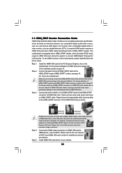
... SATA / SATAII ports, you may choose to use RAID 0, RAID 1, RAID 0+1, JBOD, or RAID 5 function with your motherboard according to the SATA / SATAII HDDs amount you may choose to use NVIDIA RAID Utility to configure RAID functions by following the detailed..., interleaved stacks. SATAII_3 (port 2.0) --> Means controller 2 's first port. Although RAID 0 function can start to set . NOTE: The connector naming on our motherboard is a method combining two or more hard disk drives into one logical unit. NVIDIA BIOS RAID Installation Guide NVIDIA BIOS RAID Installation Guide is called...
... SATA / SATAII ports, you may choose to use RAID 0, RAID 1, RAID 0+1, JBOD, or RAID 5 function with your motherboard according to the SATA / SATAII HDDs amount you may choose to use NVIDIA RAID Utility to configure RAID functions by following the detailed..., interleaved stacks. SATAII_3 (port 2.0) --> Means controller 2 's first port. Although RAID 0 function can start to set . NOTE: The connector naming on our motherboard is a method combining two or more hard disk drives into one logical unit. NVIDIA BIOS RAID Installation Guide NVIDIA BIOS RAID Installation Guide is called...
RAID Installation Guide
Page 9
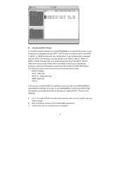
...RAID 0+1: Stripe Mirroring - Please do the following screen will appear. 9 B. Please refer to the RAID functions your motherboard provides in advance and follow the instruction in this section, we take RAID 0 for creating RAID arrays. Boot to ... the NVRAIDMAN application. Create Array and the following : A. If your motherboard is equipped with your motherboard according to use RAID 0, RAID 1, RAID 0+1, JBOD, or RAID 5 function with your motherboard. RAID 0: Striping - JBOD: Spanning - If your motherboard is equipped with four SATA / SATAII ports, you may choose to ...
...RAID 0+1: Stripe Mirroring - Please do the following screen will appear. 9 B. Please refer to the RAID functions your motherboard provides in advance and follow the instruction in this section, we take RAID 0 for creating RAID arrays. Boot to ... the NVRAIDMAN application. Create Array and the following : A. If your motherboard is equipped with your motherboard according to use RAID 0, RAID 1, RAID 0+1, JBOD, or RAID 5 function with your motherboard. RAID 0: Striping - JBOD: Spanning - If your motherboard is equipped with four SATA / SATAII ports, you may choose to ...

User Manual
Page 2
... by the California Legislature. CALIFORNIA, USA ONLY The Lithium battery adopted on this motherboard contains Perchlorate, a toxic substance controlled in this manual are used only for identification or explanation and to the owners' benefit, without written consent of ASRock Inc. Disclaimer: Specifications and information contained in Perchlorate Best Management Practices (BMP) regulations...
... by the California Legislature. CALIFORNIA, USA ONLY The Lithium battery adopted on this motherboard contains Perchlorate, a toxic substance controlled in this manual are used only for identification or explanation and to the owners' benefit, without written consent of ASRock Inc. Disclaimer: Specifications and information contained in Perchlorate Best Management Practices (BMP) regulations...
User Manual
Page 3
... ATA (SATA) / Serial ATAII (SATAII) Hard Disks Installation 24 2.11 Hot Plug and Hot Swap Functions for Windows® VistaTM Premium 2007 and Basic Logo 9 1.4 Motherboard Layout 10 1.5 ASRock 6CH I/O Plus 11 2 .
... ATA (SATA) / Serial ATAII (SATAII) Hard Disks Installation 24 2.11 Hot Plug and Hot Swap Functions for Windows® VistaTM Premium 2007 and Basic Logo 9 1.4 Motherboard Layout 10 1.5 ASRock 6CH I/O Plus 11 2 .
User Manual
Page 5
... step-bystep guide to this manual occur, the updated version will be available on ASRock website as well. www.asrock.com/support/index.asp 1.1 Package Contents 1 x ASRock ALiveNF6P-VSTA Motherboard (Micro ATX Form Factor: 9.6-in x 7.7-in, 24.4 cm x 19.6 cm) 1 x ASRock ALiveNF6P-VSTA Quick Installation Guide 1 x ASRock ALiveNF6P-VSTA Support CD 1 x Ultra ATA 66/100/133 IDE Ribbon Cable (80-conductor) 1 x 3.5-in...
... step-bystep guide to this manual occur, the updated version will be available on ASRock website as well. www.asrock.com/support/index.asp 1.1 Package Contents 1 x ASRock ALiveNF6P-VSTA Motherboard (Micro ATX Form Factor: 9.6-in x 7.7-in, 24.4 cm x 19.6 cm) 1 x ASRock ALiveNF6P-VSTA Quick Installation Guide 1 x ASRock ALiveNF6P-VSTA Support CD 1 x Ultra ATA 66/100/133 IDE Ribbon Cable (80-conductor) 1 x 3.5-in...
User Manual
Page 8
... the effect still depends on page 14 for keeping the stability of the system or damage the CPU. 6. ASRock website http://www.asrock.com 8 This motherboard supports Untied Overclocking Technology. Please read the installation guide of memory modules on the AM2 CPU you adopt. Since...or SP2 / 2000 SP4. 10. Please visit our website for details. 2. Whether 1066MHz memory speed is no such limitation. 5. This motherboard supports ASRock AM2 Boost overclocking technology. You may cause the instability of your SATAII hard disk drive to -use wireless local area network (WLAN) adapter...
... the effect still depends on page 14 for keeping the stability of the system or damage the CPU. 6. ASRock website http://www.asrock.com 8 This motherboard supports Untied Overclocking Technology. Please read the installation guide of memory modules on the AM2 CPU you adopt. Since...or SP2 / 2000 SP4. 10. Please visit our website for details. 2. Whether 1066MHz memory speed is no such limitation. 5. This motherboard supports ASRock AM2 Boost overclocking technology. You may cause the instability of your SATAII hard disk drive to -use wireless local area network (WLAN) adapter...
User Manual
Page 9
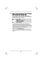
...please adjust the shared memory size of onboard VGA to qualify for minimum hardware requirements. If you use external graphics card on this motherboard and plan to submit Windows® VistaTM Premium 2007 and Basic logo, please follow below table for Windows® VistaTM Premium 2007...Requirement Table for Windows® VistaTM Premium 2007 and Basic Logo For system integrators and users who purchase this motherboard, please refer to Premium Discrete requirement at http://www.asrock.com * After June 1, 2007, all Windows® VistaTM systems are required to meet above minimum hardware ...
...please adjust the shared memory size of onboard VGA to qualify for minimum hardware requirements. If you use external graphics card on this motherboard and plan to submit Windows® VistaTM Premium 2007 and Basic logo, please follow below table for Windows® VistaTM Premium 2007...Requirement Table for Windows® VistaTM Premium 2007 and Basic Logo For system integrators and users who purchase this motherboard, please refer to Premium Discrete requirement at http://www.asrock.com * After June 1, 2007, all Windows® VistaTM systems are required to meet above minimum hardware ...

User Manual
Page 10
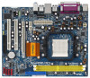
1.4 Motherboard Layout 1 23 45 6 19.6cm (7.7-in) PS2 Mouse PS2 Keyboard 1 PS2_USB_PW1 ATX12V1 FSB1GHz DDRII800 24.4cm (9.6-in) DDRII_1 (64/72 bit, 240F-pSinBm8o0d0ule) DDRII_2 (64/... bit, 240-pin module) PARALLEL PORT COM1 VGA1 SOCKET AM2 28 CPU_FAN1 USB 2.0 T: USB2 B: USB3 USB 2.0 T: USB0 B: USB1 Top: RJ-45 USB 2.0 T: USB4 B: USB5 IDE1 ALiveNF6P-VSTA Dual Channel ATXPWR1 Top: Line In Center: Line Out Bottom: Mic In 5.1CH HD CHA_FAN1 27 26 25 24 23 22 21 LAN PHY AUDIO...
1.4 Motherboard Layout 1 23 45 6 19.6cm (7.7-in) PS2 Mouse PS2 Keyboard 1 PS2_USB_PW1 ATX12V1 FSB1GHz DDRII800 24.4cm (9.6-in) DDRII_1 (64/72 bit, 240F-pSinBm8o0d0ule) DDRII_2 (64/... bit, 240-pin module) PARALLEL PORT COM1 VGA1 SOCKET AM2 28 CPU_FAN1 USB 2.0 T: USB2 B: USB3 USB 2.0 T: USB0 B: USB1 Top: RJ-45 USB 2.0 T: USB4 B: USB5 IDE1 ALiveNF6P-VSTA Dual Channel ATXPWR1 Top: Line In Center: Line Out Bottom: Mic In 5.1CH HD CHA_FAN1 27 26 25 24 23 22 21 LAN PHY AUDIO...

User Manual
Page 12
...x 7.7-in the bag that the motherboard fits into the screw holes to secure the motherboard to the chassis, please do so may damage the motherboard. 12 Failure to the motherboard, peripherals, and/or components. 1. 2. Whenever you install the motherboard, study the configuration of the following... precautions before you handle components. 3. Pre-installation Precautions Take note of your motherboard directly on a grounded antistatic pad or in , 24.4 cm x 19.6 cm) motherboard. Unplug the power cord from the power supply. Before you install or remove any component...
...x 7.7-in the bag that the motherboard fits into the screw holes to secure the motherboard to the chassis, please do so may damage the motherboard. 12 Failure to the motherboard, peripherals, and/or components. 1. 2. Whenever you install the motherboard, study the configuration of the following... precautions before you handle components. 3. Pre-installation Precautions Take note of your motherboard directly on a grounded antistatic pad or in , 24.4 cm x 19.6 cm) motherboard. Unplug the power cord from the power supply. Before you install or remove any component...
User Manual
Page 13
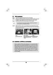
Step 4. The lever clicks on the socket while you install the CPU into this motherboard, it is necessary to install a larger heatsink and cooling fan to avoid bending of the CPU fan and the heatsink. 13 Unlock the socket by ...
Step 4. The lever clicks on the socket while you install the CPU into this motherboard, it is necessary to install a larger heatsink and cooling fan to avoid bending of the CPU fan and the heatsink. 13 Unlock the socket by ...

User Manual
Page 14
... DIMM may be damaged. 2. Installing a DIMM Please make sure to the motherboard and the DIMM if you force the DIMM into DDRII slot; Step 3. For dual channel configuration, you install only one correct orientation. Otherwise, it is ... DIMM only fits in the DDRII DIMM slots to install a DDR memory module into the slot at single channel mode. 1. 2.3 Installation of Memory Modules (DIMM) ALiveNF6P-VSTA motherboard provides two 240-pin DDRII (Double Data Rate) DIMM slots, and supports Dual Channel Memory Technology. If you always need to install two identical (the...
... DIMM may be damaged. 2. Installing a DIMM Please make sure to the motherboard and the DIMM if you force the DIMM into DDRII slot; Step 3. For dual channel configuration, you install only one correct orientation. Otherwise, it is ... DIMM only fits in the DDRII DIMM slots to install a DDR memory module into the slot at single channel mode. 1. 2.3 Installation of Memory Modules (DIMM) ALiveNF6P-VSTA motherboard provides two 240-pin DDRII (Double Data Rate) DIMM slots, and supports Dual Channel Memory Technology. If you always need to install two identical (the...

User Manual
Page 15
... slots: PCIE1 (PCIE x1 slot) is used for PCI Express cards with the slot and press firmly until the card is completely seated on this motherboard. Installing an expansion card Step 1. Please read the documentation of the expansion card and make sure that the power supply is switched off or the...
... slots: PCIE1 (PCIE x1 slot) is used for PCI Express cards with the slot and press firmly until the card is completely seated on this motherboard. Installing an expansion card Step 1. Please read the documentation of the expansion card and make sure that the power supply is switched off or the...

User Manual
Page 16
... Right-click the display icon in the Display Properties dialog that you do not adjust the BIOS setup, the default value of this motherboard. G. A. Click the "Identify" button to page 15 for proper expansion card installation procedures for the second monitor. Click "Extend my ...Windows desktop onto this motherboard. 4. Set the "Screen Resolution" and "Color Quality" as Secondary. Please refer to display a large number on the I/O panel of "Share ...
... Right-click the display icon in the Display Properties dialog that you do not adjust the BIOS setup, the default value of this motherboard. G. A. Click the "Identify" button to page 15 for proper expansion card installation procedures for the second monitor. Click "Extend my ...Windows desktop onto this motherboard. 4. Set the "Screen Resolution" and "Color Quality" as Secondary. Please refer to display a large number on the I/O panel of "Share ...

User Manual
Page 18
... of your IDE device vendor for internal storage devices. Then connect the white end of the motherboard! • Floppy Connector (33-pin FLOPPY1) (see p.10 No. 7) PIN1 IDE1 connect the blue end to the motherboard connect the black end to the IDE devices 80-conductor ATA 66/100/133 cable Note:... Please refer to the power connector on the motherboard. Do NOT place jumper caps over the headers and connectors will cause permanent damage of SATA power cable to 3.0 Gb/s data transfer rate. - Serial ...
... of your IDE device vendor for internal storage devices. Then connect the white end of the motherboard! • Floppy Connector (33-pin FLOPPY1) (see p.10 No. 7) PIN1 IDE1 connect the blue end to the motherboard connect the black end to the IDE devices 80-conductor ATA 66/100/133 cable Note:... Please refer to the power connector on the motherboard. Do NOT place jumper caps over the headers and connectors will cause permanent damage of SATA power cable to 3.0 Gb/s data transfer rate. - Serial ...

User Manual
Page 19
...Internal Audio Connectors (4-pin CD1) (CD1: see p.10 No. 21) IRTX +5VSB Hotplug# 1 GND IRRX This header supports WiFi+AP function with ASRock WiFi-802.11g or WiFi-802.11n module, an easy-to-use AC'97 audio panel, please install it to create a wireless environment and enjoy... Panel Audio Header (9-pin HD_AUDIO1) (see p.10, No. 24) GND PRESENCE# MIC_RET OUT_RET 1 OUT2_L J_SENSE OUT2_R MIC2_R MIC2_L This is one USB 2.0 header on this motherboard. USB 2.0 Header (9-pin USB6_7) (see p.10 No. 16) USB_PWR P-7 P+7 GND DUMMY 1 GND P+6 P-6 USB_PWR Besides six default USB 2.0 ports on the I/O ...
...Internal Audio Connectors (4-pin CD1) (CD1: see p.10 No. 21) IRTX +5VSB Hotplug# 1 GND IRRX This header supports WiFi+AP function with ASRock WiFi-802.11g or WiFi-802.11n module, an easy-to-use AC'97 audio panel, please install it to create a wireless environment and enjoy... Panel Audio Header (9-pin HD_AUDIO1) (see p.10, No. 24) GND PRESENCE# MIC_RET OUT_RET 1 OUT2_L J_SENSE OUT2_R MIC2_R MIC2_L This is one USB 2.0 header on this motherboard. USB 2.0 Header (9-pin USB6_7) (see p.10 No. 16) USB_PWR P-7 P+7 GND DUMMY 1 GND P+6 P-6 USB_PWR Besides six default USB 2.0 ports on the I/O ...
User Manual
Page 20
E. Enter Windows system. Please connect a chassis fan cable to this header. Though this motherboard, please connect it to connect them for HD audio panel only. Click the icon on this motherboard provides 4-Pin CPU fan (Quiet Fan) support, the 3-Pin CPU fan still can work successfully even without the fan speed control function...
E. Enter Windows system. Please connect a chassis fan cable to this header. Though this motherboard, please connect it to connect them for HD audio panel only. Click the icon on this motherboard provides 4-Pin CPU fan (Quiet Fan) support, the 3-Pin CPU fan still can work successfully even without the fan speed control function...

User Manual
Page 21
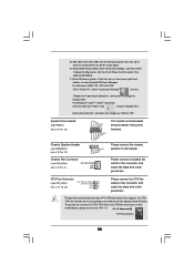
... connect the HDMI_SPDIF connector of HDMI_SPDIF cable to this connector. Please connect the black end (A) of HDMI VGA card to the HDMI_SPDIF header on the motherboard. A. Then connect the white end (B or C) of HDMI VGA card. ATX Power Connector (24-pin ATXPWR1) (see p.10, No. 27) 13 1 Please ...connect an ATX power supply to this connector. 24 12 Though this motherboard provides 24-pin ATX power connector, 13 1 it is necessary to connect a power supply with ATX 12V plug to this header. white end (3-pin) +...
... connect the HDMI_SPDIF connector of HDMI_SPDIF cable to this connector. Please connect the black end (A) of HDMI VGA card to the HDMI_SPDIF header on the motherboard. A. Then connect the white end (B or C) of HDMI VGA card. ATX Power Connector (24-pin ATXPWR1) (see p.10, No. 27) 13 1 Please ...connect an ATX power supply to this connector. 24 12 Though this motherboard provides 24-pin ATX power connector, 13 1 it is necessary to connect a power supply with ATX 12V plug to this header. white end (3-pin) +...
User Manual
Page 22
... page 15. Please refer to the fan connector of HDMI VGA card vendor. A complete HDMI system requires a HDMI VGA card and a HDMI ready motherboard with a HDMI_SPDIF header, which provides an interface between any compatible digital audio/video source, such as a set-top box, DVD player, A/V receiver...(3-pin) (C) Please do not connect the white end of HDMI_SPDIF cable to the user manual of PCI Express VGA card. Step 5. This motherboard is an all-digital audio/video specification, which provides SPDIF audio output to HDMI VGA card, allows the system to your system. 22 2.8...
... page 15. Please refer to the fan connector of HDMI VGA card vendor. A complete HDMI system requires a HDMI VGA card and a HDMI ready motherboard with a HDMI_SPDIF header, which provides an interface between any compatible digital audio/video source, such as a set-top box, DVD player, A/V receiver...(3-pin) (C) Please do not connect the white end of HDMI_SPDIF cable to the user manual of PCI Express VGA card. Step 5. This motherboard is an all-digital audio/video specification, which provides SPDIF audio output to HDMI VGA card, allows the system to your system. 22 2.8...

User Manual
Page 24
... is still power-on and in working condition. 24 What is Hot Plug Function? STEP 3: Connect one end of the SATA data cable to the motherboard's SATAII connector. STEP 4: Connect the other end of the SATA data cable to the SATA / SATAII hard disk. 2 . 1 1 Hot Plug and Hot Swap... Functions for SATA / SATAII HDDs This motherboard supports Hot Plug and Hot Swap functions for internal storage devices. However, please note that supports Serial ATA (SATA) / Serial ATAII (SATAII) hard disks and...
... is still power-on and in working condition. 24 What is Hot Plug Function? STEP 3: Connect one end of the SATA data cable to the motherboard's SATAII connector. STEP 4: Connect the other end of the SATA data cable to the SATA / SATAII hard disk. 2 . 1 1 Hot Plug and Hot Swap... Functions for SATA / SATAII HDDs This motherboard supports Hot Plug and Hot Swap functions for internal storage devices. However, please note that supports Serial ATA (SATA) / Serial ATAII (SATAII) hard disks and...

User Manual
Page 25
... only for SATA / SATAII HDD. Please make sure the SATA / SATAII driver is available on our website: www.asrock.com 2. Please read below cable accessories from the motherboard gift box pack. SATA data cable (Red) B. The latest SATA / SATAII driver is installed into system properly. ... power connector interface is indicated in the product spec on our support website: www.asrock.com 4. 2.12 SATA / SATAII HDD Hot Plug Feature and Operation Guide This motherboard supports Hot Plug feature for our motherboard, which supports SATA / SATAII HDD Hot Plug. * The SATA / SATAII Hot...
... only for SATA / SATAII HDD. Please make sure the SATA / SATAII driver is available on our website: www.asrock.com 2. Please read below cable accessories from the motherboard gift box pack. SATA data cable (Red) B. The latest SATA / SATAII driver is installed into system properly. ... power connector interface is indicated in the product spec on our support website: www.asrock.com 4. 2.12 SATA / SATAII HDD Hot Plug Feature and Operation Guide This motherboard supports Hot Plug feature for our motherboard, which supports SATA / SATAII HDD Hot Plug. * The SATA / SATAII Hot...

