
User Manual
Page 3
...CPU Fan and Heatsink 14 2.3 Installation of Memory Modules (DIMM 15 2.4 Expansion Slots (PCI Express, PCI, and HDMR Slots 17 2.5 Easy Dual Monitor Feature (ALiveNF6G-DVI 18 2.6 Easy Multi Monitor Feature (ALiveNF6G-DVI / ALiveNF6G-VSTA 20 2.7 Jumpers Setup 21 2.8 ... 2.12 Hot Plug and Hot Swap Functions for Windows® VistaTM Premium and Basic Logo 9 1.4 Motherboard Layout (ALiveNF6G-DVI 10 1.5 Motherboard Layout (ALiveNF6G-VSTA 11 1.6 HD 8CH I/O (ALiveNF6G-DVI / ALiveNF6G-VSTA 12 2 . Contents 1 . BIOS SETUP UTILITY 32 3.1 Introduction 32 3.1.1 BIOS Menu Bar 32 3.1.2 Navigation...
...CPU Fan and Heatsink 14 2.3 Installation of Memory Modules (DIMM 15 2.4 Expansion Slots (PCI Express, PCI, and HDMR Slots 17 2.5 Easy Dual Monitor Feature (ALiveNF6G-DVI 18 2.6 Easy Multi Monitor Feature (ALiveNF6G-DVI / ALiveNF6G-VSTA 20 2.7 Jumpers Setup 21 2.8 ... 2.12 Hot Plug and Hot Swap Functions for Windows® VistaTM Premium and Basic Logo 9 1.4 Motherboard Layout (ALiveNF6G-DVI 10 1.5 Motherboard Layout (ALiveNF6G-VSTA 11 1.6 HD 8CH I/O (ALiveNF6G-DVI / ALiveNF6G-VSTA 12 2 . Contents 1 . BIOS SETUP UTILITY 32 3.1 Introduction 32 3.1.1 BIOS Menu Bar 32 3.1.2 Navigation...
User Manual
Page 6
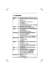
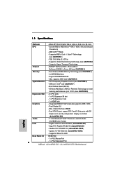
...; GeForce 6100 / nForce 430 or GeForce 6150SE / nForce 430 (see CAUTION 2) - Dual Channel DDRII Memory Technology (see CAUTION 6) - Max. CPU Frequency Stepless Control (see CAUTION 4) - 4 x DDRII DIMM slots - ASRock U-COP (see CAUTION 1) - shared memory 256MB - Giga PHY Realtek RTL8211B (ALiveNF6G-DVI) - Supports Wake-On-LAN HD 8CH I /O - Supports AMD's Cool 'n' QuietTM Technology (see CAUTION 7) - FSB...
...; GeForce 6100 / nForce 430 or GeForce 6150SE / nForce 430 (see CAUTION 2) - Dual Channel DDRII Memory Technology (see CAUTION 6) - Max. CPU Frequency Stepless Control (see CAUTION 4) - 4 x DDRII DIMM slots - ASRock U-COP (see CAUTION 1) - shared memory 256MB - Giga PHY Realtek RTL8211B (ALiveNF6G-DVI) - Supports Wake-On-LAN HD 8CH I /O - Supports AMD's Cool 'n' QuietTM Technology (see CAUTION 7) - FSB...
User Manual
Page 8
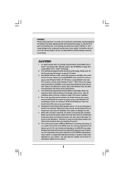
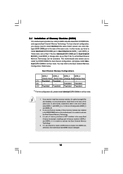
...all CPU/DRAM configurations. Before you implement Dual Channel Memory Technology, make sure to read "Untied Overclocking Technology" on page 50 to enable AMD's Cool 'n' QuietTM technology. 2. This motherboard supports ASRock AM2 Boost overclocking technology. Enabling this function will ...and devices of your own risk and expense. This motherboard supports Untied Overclocking Technology. This motherboard supports Dual Channel Memory Technology. Although this function for proper installation. 5. If your system is unstable after AM2 Boost function is enabled...
...all CPU/DRAM configurations. Before you implement Dual Channel Memory Technology, make sure to read "Untied Overclocking Technology" on page 50 to enable AMD's Cool 'n' QuietTM technology. 2. This motherboard supports ASRock AM2 Boost overclocking technology. Enabling this function will ...and devices of your own risk and expense. This motherboard supports Untied Overclocking Technology. This motherboard supports Dual Channel Memory Technology. Although this function for proper installation. 5. If your system is unstable after AM2 Boost function is enabled...
User Manual
Page 9
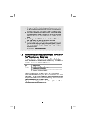
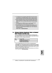
...to adjust your SATAII hard disk drive to Premium Discrete requirement at http://www.asrock.com 9 Please visit our website for proper connection. 10. If you plan to use onboard VGA with total system memory size above . * If you use external graphics card on updating now. ...driver, we will update it to submit Windows® VistaTM Premium and Basic logo, please follow the below table for minimum hardware requirement. ASRock website http://www.asrock.com 1.3 Minimum Hardware Requirement Table for USB 2.0 works fine under Microsoft® Windows® VistaTM 64-bit / VistaTM / XP ...
...to adjust your SATAII hard disk drive to Premium Discrete requirement at http://www.asrock.com 9 Please visit our website for proper connection. 10. If you plan to use onboard VGA with total system memory size above . * If you use external graphics card on updating now. ...driver, we will update it to submit Windows® VistaTM Premium and Basic logo, please follow the below table for minimum hardware requirement. ASRock website http://www.asrock.com 1.3 Minimum Hardware Requirement Table for USB 2.0 works fine under Microsoft® Windows® VistaTM 64-bit / VistaTM / XP ...
User Manual
Page 10
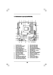
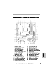
...28 27 Top: LINE IN Center: FRONT Bottom: MIC IN LAN PHY CD1 AUDIO CODEC HDMI_SPDIF1 1 1 HD_AUDIO1 ` PCIE1 PCI EXPRESS RAID ALiveNF6G-DVI PCI1 PCI2 PCIE2 7.1CH HD HDMR1 CMOS BATTERY CLRCMOS1 1 NVIDIA GeForce 6100 / nForce 430 or GeForce 6150SE / nForce 430 Chipset RoHS ... Orange) 8 Infrared Module Header (IR1) 9 Game Port Header (GAME1) 10 Floppy Connector (FLOPPY1) 11 Primary IDE Connector (IDE1, Blue) 12 Flash Memory 13 Fourth SATAII Connector (SATAII_4, Red) 14 Third SATAII Connector (SATAII_3, Red) 15 Chassis Fan Connector (CHA_FAN1) 16 Primary SATAII Connector (SATAII_1, Red)...
...28 27 Top: LINE IN Center: FRONT Bottom: MIC IN LAN PHY CD1 AUDIO CODEC HDMI_SPDIF1 1 1 HD_AUDIO1 ` PCIE1 PCI EXPRESS RAID ALiveNF6G-DVI PCI1 PCI2 PCIE2 7.1CH HD HDMR1 CMOS BATTERY CLRCMOS1 1 NVIDIA GeForce 6100 / nForce 430 or GeForce 6150SE / nForce 430 Chipset RoHS ... Orange) 8 Infrared Module Header (IR1) 9 Game Port Header (GAME1) 10 Floppy Connector (FLOPPY1) 11 Primary IDE Connector (IDE1, Blue) 12 Flash Memory 13 Fourth SATAII Connector (SATAII_4, Red) 14 Third SATAII Connector (SATAII_3, Red) 15 Chassis Fan Connector (CHA_FAN1) 16 Primary SATAII Connector (SATAII_1, Red)...

User Manual
Page 11
...FLOPPY1) 28 PCI Express x1 Slot (PCIE2) 11 Primary IDE Connector (IDE1, Blue) 29 Internal Audio Connector: CD1 (Black) 12 Flash Memory 30 PCI Slots (PCI1- 2) 13 Fourth SATAII Connector (SATAII_4, Red) 31 PCI Express x16 Slot (PCIE1) 14 Third SATAII Connector (...ATX Power Connector (ATXPWR1) 15 Chassis Fan Connector (CHA_FAN1) 33 Serial Port Connector (COM1) 16 Primary SATAII Connector (SATAII_1, Red) 11 1.5 Motherboard Layout (ALiveNF6G-VSTA) 1 2 34 5 67 8 24.4cm (9.6-in) PS2 Keyboard PS2 Mouse 1 PS2_USB_PW1 ATX12V1 CPU_FAN1 IR1 1 9 Super I/O GAME1 1 Dual Core...
...FLOPPY1) 28 PCI Express x1 Slot (PCIE2) 11 Primary IDE Connector (IDE1, Blue) 29 Internal Audio Connector: CD1 (Black) 12 Flash Memory 30 PCI Slots (PCI1- 2) 13 Fourth SATAII Connector (SATAII_4, Red) 31 PCI Express x16 Slot (PCIE1) 14 Third SATAII Connector (...ATX Power Connector (ATXPWR1) 15 Chassis Fan Connector (CHA_FAN1) 33 Serial Port Connector (COM1) 16 Primary SATAII Connector (SATAII_1, Red) 11 1.5 Motherboard Layout (ALiveNF6G-VSTA) 1 2 34 5 67 8 24.4cm (9.6-in) PS2 Keyboard PS2 Mouse 1 PS2_USB_PW1 ATX12V1 CPU_FAN1 IR1 1 9 Super I/O GAME1 1 Dual Core...
User Manual
Page 15
... dual channel configuration, and please install identical DDRII DIMMs in the DDRII DIMM slots on this motherboard and DIMM may refer to the Dual Channel Memory Configuration Table below. In other words, install them in DDRII_1 and DDRII_3, it is unable to install identical (the same brand, speed, size ...either in the set of yellow slots (DDRII_1 and DDRII_2), or in all four slots. otherwise, this motherboard, it is unable to install a DDR memory module into DDRII slot; see p.10/p.11 No.6) or identical DDRII DIMM pair in Dual Channel B (DDRII_3 and DDRII_4; If only one...
... dual channel configuration, and please install identical DDRII DIMMs in the DDRII DIMM slots on this motherboard and DIMM may refer to the Dual Channel Memory Configuration Table below. In other words, install them in DDRII_1 and DDRII_3, it is unable to install identical (the same brand, speed, size ...either in the set of yellow slots (DDRII_1 and DDRII_2), or in all four slots. otherwise, this motherboard, it is unable to install a DDR memory module into DDRII slot; see p.10/p.11 No.6) or identical DDRII DIMM pair in Dual Channel B (DDRII_3 and DDRII_4; If only one...

User Manual
Page 20
... to enter BIOS setup. Press to page 17 for proper expansion card installation procedures for the second monitor. Enter "Share Memory" option to adjust the memory capability to [16MB], [32MB], [64MB], [128MB], or [256MB] to your primary monitor, and then select "Primary... Install the onboard VGA driver to enable the function of this step are under Windows® XP environment. 2.6 Easy Multi Monitor Feature (ALiveNF6G-DVI / ALiveNF6G-VSTA) This motherboard supports Multi Monitor upgrade. Please refer to the following steps to display a large number on the I/O panel of onboard ...
... to enter BIOS setup. Press to page 17 for proper expansion card installation procedures for the second monitor. Enter "Share Memory" option to adjust the memory capability to [16MB], [32MB], [64MB], [128MB], or [256MB] to your primary monitor, and then select "Primary... Install the onboard VGA driver to enable the function of this step are under Windows® XP environment. 2.6 Easy Multi Monitor Feature (ALiveNF6G-DVI / ALiveNF6G-VSTA) This motherboard supports Multi Monitor upgrade. Please refer to the following steps to display a large number on the I/O panel of onboard ...

User Manual
Page 32
3. The Flash Memory on . You may also restart by pressing the reset button on the menu bar, and then press to configure your screen. 3.1.1 BIOS Menu Bar The ...
3. The Flash Memory on . You may also restart by pressing the reset button on the menu bar, and then press to configure your screen. 3.1.1 BIOS Menu Bar The ...
User Manual
Page 33
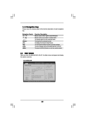
...] [Wed 07/12/2006] BIOS Version : ALiveNF6G-DVI BIOS P1.0 Processor Type : AMD Athlon(tm) 64 Processor 3400+ (64bit supported) Processor Speed : 2200 MHz Microcode Update : F7A/3A L1 Cache Size : 128KB L2 Cache Size : 512KB Total Memory DDRII 1 DDRII 2 DDRII 3 DDRII 4 : 512MB with 64MB shared memory Dual-Channel Memory Mode : 256MB/266MHz (DDRII533) : 256MB...
...] [Wed 07/12/2006] BIOS Version : ALiveNF6G-DVI BIOS P1.0 Processor Type : AMD Athlon(tm) 64 Processor 3400+ (64bit supported) Processor Speed : 2200 MHz Microcode Update : F7A/3A L1 Cache Size : 128KB L2 Cache Size : 512KB Total Memory DDRII 1 DDRII 2 DDRII 3 DDRII 4 : 512MB with 64MB shared memory Dual-Channel Memory Mode : 256MB/266MHz (DDRII533) : 256MB...
User Manual
Page 34
...items: CPU Configuration, Chipset Configuration, ACPI Configuration, IDE Configuration, PCIPnP Configuration, Floppy Configuration, SuperIO Configuration, and USB Configuration. ALiveNF6G-VSTA BIOS SETUP UTILITY Main Advanced H/W Monitor Boot Security Exit System Overview System Time System Date [17:00:09] [Wed... Speed : 2200 MHz Microcode Update : F7A/3A L1 Cache Size : 128KB L2 Cache Size : 512KB Total Memory DDRII 1 DDRII 2 DDRII 3 DDRII 4 : 512MB with 64MB shared memory Dual-Channel Memory Mode : 256MB/266MHz (DDRII533) : 256MB/266MHz (DDRII533) : None : None Use [Enter], [TAB] or...
...items: CPU Configuration, Chipset Configuration, ACPI Configuration, IDE Configuration, PCIPnP Configuration, Floppy Configuration, SuperIO Configuration, and USB Configuration. ALiveNF6G-VSTA BIOS SETUP UTILITY Main Advanced H/W Monitor Boot Security Exit System Overview System Time System Date [17:00:09] [Wed... Speed : 2200 MHz Microcode Update : F7A/3A L1 Cache Size : 128KB L2 Cache Size : 512KB Total Memory DDRII 1 DDRII 2 DDRII 3 DDRII 4 : 512MB with 64MB shared memory Dual-Channel Memory Mode : 256MB/266MHz (DDRII533) : 256MB/266MHz (DDRII533) : None : None Use [Enter], [TAB] or...
User Manual
Page 35
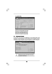
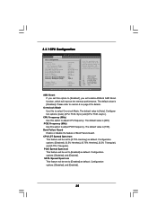
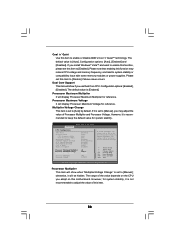
...to [Enabled] as default. PCIE Frequency (MHz) Use this option to [Enabled], you will enable ASRock AM2 Boost function, which will improve the memory performance. SATA Spread Spectrum This feature will be left at the rated frequency/voltage. 3.3.1 CPU Configuration... Guard CPU/LDT Spread Spectrum PCIE Spread Spectrum SATA Spread Spectrum Cool' n' Quiet Dual Core Support Processor Maximum Multiplier Processor Maximum Voltage Multiplier/Voltage Change Memory Clock Flexibility Option CAS Latency TRAS [Disabled] [Auto] [200] [100] [Enabled] [0.75% Hershey] [Enabled] [Enabled] [Auto] [Enabled] ...
...to [Enabled] as default. PCIE Frequency (MHz) Use this option to [Enabled], you will enable ASRock AM2 Boost function, which will improve the memory performance. SATA Spread Spectrum This feature will be left at the rated frequency/voltage. 3.3.1 CPU Configuration... Guard CPU/LDT Spread Spectrum PCIE Spread Spectrum SATA Spread Spectrum Cool' n' Quiet Dual Core Support Processor Maximum Multiplier Processor Maximum Voltage Multiplier/Voltage Change Memory Clock Flexibility Option CAS Latency TRAS [Disabled] [Auto] [200] [100] [Enabled] [0.75% Hershey] [Enabled] [Enabled] [Auto] [Enabled] ...
User Manual
Page 36
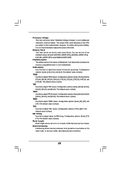
... will be left at the rated frequency/voltage. otherwise, it is set to [Manual], you may reduce CPU voltage and memory frequency, and lead to system stability or compatibility issue with some memory modules or power supplies. Please set this item to [Disable] if above issue occurs. Configuration optiona: [Enabled], [Disabled]. The...
... will be left at the rated frequency/voltage. otherwise, it is set to [Manual], you may reduce CPU voltage and memory frequency, and lead to system stability or compatibility issue with some memory modules or power supplies. Please set this item to [Disable] if above issue occurs. Configuration optiona: [Enabled], [Disabled]. The...
User Manual
Page 37
.... Burst Length Burst length can be hidden. It will allow better tolerance for MA timing. TRAS Use this to adjust values for memory compatibility when it will be set to adjust the means of this motherboard. TRP Use this item to [Enabled]. Configuration options: ... use the 4 beats. Configuration options: [Auto], [2.0], [3.0], and [2.5]. Configuration options: [Auto], [2T], [3T], and [4T]. The default value is [Auto]. Memory Clock This item can set one of the value depends on the CPU you adopt on the same node, or accross nodes, decreasing access contention...
.... Burst Length Burst length can be hidden. It will allow better tolerance for MA timing. TRAS Use this to adjust values for memory compatibility when it will be set to adjust the means of this motherboard. TRP Use this item to [Enabled]. Configuration options: ... use the 4 beats. Configuration options: [Auto], [2.0], [3.0], and [2.5]. Configuration options: [Auto], [2T], [3T], and [4T]. The default value is [Auto]. Memory Clock This item can set one of the value depends on the CPU you adopt on the same node, or accross nodes, decreasing access contention...

User Manual
Page 38
... item to select the type of Primary VGA in case of multiple video controllers. NB Link Width This feature allows you to NB link width. Memory Hole Use this feature is [Disabled]. It allows you to NB link frequency. Configuration options: [PCI], [Onboard] and [PCI Express]. CPU - CPU... - Configuration options: [Auto], [8 bit], and [16 bit]. 38 OnBoard LAN This allows you to enable or disable memory hole. NB Link Speed This feature allows you select [Auto], the onboard HD Audio will switch the PCI Bus scanning order while searching for video...
... item to select the type of Primary VGA in case of multiple video controllers. NB Link Width This feature allows you to NB link width. Memory Hole Use this feature is [Disabled]. It allows you to NB link frequency. Configuration options: [PCI], [Onboard] and [PCI Express]. CPU - CPU... - Configuration options: [Auto], [8 bit], and [16 bit]. 38 OnBoard LAN This allows you to enable or disable memory hole. NB Link Speed This feature allows you select [Auto], the onboard HD Audio will switch the PCI Bus scanning order while searching for video...

Quick Installation Guide
Page 2
...Module Header (IR1) 9 Game Port Header (GAME1) 10 Floppy Connector (FLOPPY1) 11 Primary IDE Connector (IDE1, Blue) 12 Flash Memory 13 Fourth SATAII Connector (SATAII_4, Red) 14 Third SATAII Connector (SATAII_3, Red) 15 Chassis Fan Connector (CHA_FAN1) 16 Primary SATAII ...Slots (PCI1- 2) 31 PCI Express x16 Slot (PCIE1) 32 ATX Power Connector (ATXPWR1) 33 Serial Port Connector (COM1) 2 ASRock ALiveNF6G-DVI / ALiveNF6G-VSTA Motherboard Motherboard Layout (ALiveNF6G-DVI) English 1 PS2_USB_PW1 Jumper 2 ATX 12V Power Connector (ATX12V1) 3 CPU Heatsink Retention Module 4 AM2 940-Pin CPU Socket 5 CPU...
...Module Header (IR1) 9 Game Port Header (GAME1) 10 Floppy Connector (FLOPPY1) 11 Primary IDE Connector (IDE1, Blue) 12 Flash Memory 13 Fourth SATAII Connector (SATAII_4, Red) 14 Third SATAII Connector (SATAII_3, Red) 15 Chassis Fan Connector (CHA_FAN1) 16 Primary SATAII ...Slots (PCI1- 2) 31 PCI Express x16 Slot (PCIE1) 32 ATX Power Connector (ATXPWR1) 33 Serial Port Connector (COM1) 2 ASRock ALiveNF6G-DVI / ALiveNF6G-VSTA Motherboard Motherboard Layout (ALiveNF6G-DVI) English 1 PS2_USB_PW1 Jumper 2 ATX 12V Power Connector (ATX12V1) 3 CPU Heatsink Retention Module 4 AM2 940-Pin CPU Socket 5 CPU...
Quick Installation Guide
Page 3
...Header (IR1) 9 Game Port Header (GAME1) 10 Floppy Connector (FLOPPY1) 11 Primary IDE Connector (IDE1, Blue) 12 Flash Memory 13 Fourth SATAII Connector (SATAII_4, Red) 14 Third SATAII Connector (SATAII_3, Red) 15 Chassis Fan Connector (CHA_FAN1) 16 Primary ... x16 Slot (PCIE1) 32 ATX Power Connector (ATXPWR1) 33 Serial Port Connector (COM1) 3 ASRock ALiveNF6G-DVI / ALiveNF6G-VSTA Motherboard Yellow) 7 2 x 240-pin DDRII DIMM Slots (Dual Channel B: DDRII_3, DDRII_4; Motherboard Layout (ALiveNF6G-VSTA) English 1 PS2_USB_PW1 Jumper 2 ATX 12V Power Connector (ATX12V1) 3 CPU Heatsink Retention Module...
...Header (IR1) 9 Game Port Header (GAME1) 10 Floppy Connector (FLOPPY1) 11 Primary IDE Connector (IDE1, Blue) 12 Flash Memory 13 Fourth SATAII Connector (SATAII_4, Red) 14 Third SATAII Connector (SATAII_3, Red) 15 Chassis Fan Connector (CHA_FAN1) 16 Primary ... x16 Slot (PCIE1) 32 ATX Power Connector (ATXPWR1) 33 Serial Port Connector (COM1) 3 ASRock ALiveNF6G-DVI / ALiveNF6G-VSTA Motherboard Yellow) 7 2 x 240-pin DDRII DIMM Slots (Dual Channel B: DDRII_3, DDRII_4; Motherboard Layout (ALiveNF6G-VSTA) English 1 PS2_USB_PW1 Jumper 2 ATX 12V Power Connector (ATX12V1) 3 CPU Heatsink Retention Module...
Quick Installation Guide
Page 6
... I/O - 1 x PS/2 Mouse Port - 1 x PS/2 Keyboard Port 6 ASRock ALiveNF6G-DVI / ALiveNF6G-VSTA Motherboard English 1.2 Specifications Platform - Supports AMD's Cool 'n' QuietTM Technology (see CAUTION 7) - Support DDRII800/667/533 - shared memory 256MB - Gigabit LAN 10/100/1000 Mb/s (ALiveNF6G-DVI) - FSB 1000 MHz (2.0 GT/s) - Dual Channel DDRII Memory Technology (see CAUTION 3) Memory - Max. Realtek PHY RTL8201CL (ALiveNF6G-VSTA) - NVIDIA® GeForce 6100 / nForce...
... I/O - 1 x PS/2 Mouse Port - 1 x PS/2 Keyboard Port 6 ASRock ALiveNF6G-DVI / ALiveNF6G-VSTA Motherboard English 1.2 Specifications Platform - Supports AMD's Cool 'n' QuietTM Technology (see CAUTION 7) - Support DDRII800/667/533 - shared memory 256MB - Gigabit LAN 10/100/1000 Mb/s (ALiveNF6G-DVI) - FSB 1000 MHz (2.0 GT/s) - Dual Channel DDRII Memory Technology (see CAUTION 3) Memory - Max. Realtek PHY RTL8201CL (ALiveNF6G-VSTA) - NVIDIA® GeForce 6100 / nForce...
Quick Installation Guide
Page 8
..., the difference in device name under Windows® XP and Windows® VistaTM. Before you implement Dual Channel Memory Technology, make sure to spray thermal grease between the CPU and the heatsink when you adopt. Enabling this motherboard....430. This motherboard supports ASRock AM2 Boost overclocking technology. This motherboard supports Dual Channel Memory Technology. To improve heat dissipation, remember to read "Untied Overclocking Technology" on page 11 for keeping the stability of your system. 8 ASRock ALiveNF6G-DVI / ALiveNF6G-VSTA Motherboard English If...
..., the difference in device name under Windows® XP and Windows® VistaTM. Before you implement Dual Channel Memory Technology, make sure to spray thermal grease between the CPU and the heatsink when you adopt. Enabling this motherboard....430. This motherboard supports ASRock AM2 Boost overclocking technology. This motherboard supports Dual Channel Memory Technology. To improve heat dissipation, remember to read "Untied Overclocking Technology" on page 11 for keeping the stability of your system. 8 ASRock ALiveNF6G-DVI / ALiveNF6G-VSTA Motherboard English If...
Quick Installation Guide
Page 9
... to SATAII mode. Power Management for Microsoft® Windows® VistaTM / VistaTM 64-bit driver and related information. ASRock website http://www.asrock.com 1.3 Minimum Hardware Requirement Table for Windows® VistaTM Premium and Basic Logo For system integrators and users who purchase...onboard VGA with total system memory size above 512MB and plan to submit Windows® VistaTM Premium or Basic logo, please adjust the shared memory size of onboard VGA to Premium Discrete requirement at http://www.asrock.com English 9 ASRock ALiveNF6G-DVI / ALiveNF6G-VSTA Motherboard You can ...
... to SATAII mode. Power Management for Microsoft® Windows® VistaTM / VistaTM 64-bit driver and related information. ASRock website http://www.asrock.com 1.3 Minimum Hardware Requirement Table for Windows® VistaTM Premium and Basic Logo For system integrators and users who purchase...onboard VGA with total system memory size above 512MB and plan to submit Windows® VistaTM Premium or Basic logo, please adjust the shared memory size of onboard VGA to Premium Discrete requirement at http://www.asrock.com English 9 ASRock ALiveNF6G-DVI / ALiveNF6G-VSTA Motherboard You can ...

