RAID Installation Guide
Page 1
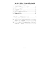
NVIDIA RAID Installation Guide 1. NVIDIA BIOS RAID Installation Guide 2 1.1 Introduction to RAID 2 1.2 RAID Configurations Precautions 3 1.3 Create Disk Array 4 2. NVIDIA Windows RAID Installation Guide 8 2.1 NVIDIA Windows RAID Installation Guide for Windows 2000 / XP / XP 64-bit Users 8 2.2 NVIDIA Windows RAID Installation Guide for Windows Vista / Vista 64-bit Users 18 1
NVIDIA RAID Installation Guide 1. NVIDIA BIOS RAID Installation Guide 2 1.1 Introduction to RAID 2 1.2 RAID Configurations Precautions 3 1.3 Create Disk Array 4 2. NVIDIA Windows RAID Installation Guide 8 2.1 NVIDIA Windows RAID Installation Guide for Windows 2000 / XP / XP 64-bit Users 8 2.2 NVIDIA Windows RAID Installation Guide for Windows Vista / Vista 64-bit Users 18 1

RAID Installation Guide
Page 2
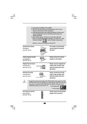
After you make a SATA / SATAII driver diskette, press to enter BIOS setup to set . If your motherboard is different with your motherboard according to the SATA / SATAII HDDs amount you may choose to RAID mode by ... will cause data damage or data loss. 2 If your motherboard provides in advance and follow the instruction in parallel, interleaved stacks. WARNING!! NVIDIA BIOS RAID Installation Guide NVIDIA BIOS RAID Installation Guide is a method combining two or more hard disk drives into one logical unit. SATAII_2 (port 1.1) --> Means controller 1 's second port. SATAII_1...
After you make a SATA / SATAII driver diskette, press to enter BIOS setup to set . If your motherboard is different with your motherboard according to the SATA / SATAII HDDs amount you may choose to RAID mode by ... will cause data damage or data loss. 2 If your motherboard provides in advance and follow the instruction in parallel, interleaved stacks. WARNING!! NVIDIA BIOS RAID Installation Guide NVIDIA BIOS RAID Installation Guide is a method combining two or more hard disk drives into one logical unit. SATAII_2 (port 1.1) --> Means controller 1 's second port. SATAII_1...

RAID Installation Guide
Page 4
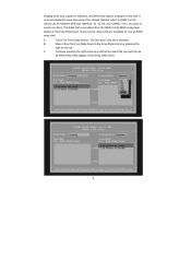
.... 3. The RAID prompt appears as default. After rebooting your new RAID array. After you to RAID mode, the below window appears. 2. After adjusting the system BIOS to press .
.... 3. The RAID prompt appears as default. After rebooting your new RAID array. After you to RAID mode, the below window appears. 2. After adjusting the system BIOS to press .
RAID Installation Guide
Page 6
... the Free Disks block. The disks that you enabled from the Free Disks block to the Free Disks section. Move it from the RAID Config BIOS setup page appear in the list is selected. Continue pressing the right-arrow key until all the disks that are the drives that you have...
... the Free Disks block. The disks that you enabled from the Free Disks block to the Free Disks section. Move it from the RAID Config BIOS setup page appear in the list is selected. Continue pressing the right-arrow key until all the disks that are the drives that you have...
RAID Installation Guide
Page 9
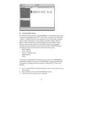
...: - The RAID items which may be mentioned in this section, we take RAID 0 for creating RAID arrays. RAID 1: Mirroring - B. JBOD: Spanning - Go to the system BIOS and make sure that the drives that you may choose to use RAID 0, RAID 1, or JBOD function with your motherboard is equipped with two SATA...
...: - The RAID items which may be mentioned in this section, we take RAID 0 for creating RAID arrays. RAID 1: Mirroring - B. JBOD: Spanning - Go to the system BIOS and make sure that the drives that you may choose to use RAID 0, RAID 1, or JBOD function with your motherboard is equipped with two SATA...

User Manual
Page 3
... Expansion Slots (PCI Express, PCI, and HDMR Slots 17 2.5 Easy Dual Monitor Feature (ALiveNF6G-DVI 18 2.6 Easy Multi Monitor Feature (ALiveNF6G-DVI / ALiveNF6G-VSTA 20 2.7 Jumpers Setup 21 2.8 Onboard Headers and Connectors 22 2.9 HDMI_SPDIF Header Connection ... for Windows® VistaTM Premium and Basic Logo 9 1.4 Motherboard Layout (ALiveNF6G-DVI 10 1.5 Motherboard Layout (ALiveNF6G-VSTA 11 1.6 HD 8CH I/O (ALiveNF6G-DVI / ALiveNF6G-VSTA 12 2 . BIOS SETUP UTILITY 32 3.1 Introduction 32 3.1.1 BIOS Menu Bar 32 3.1.2 Navigation Keys 32 3 Introduction 5 1.1 Package Contents ...
... Expansion Slots (PCI Express, PCI, and HDMR Slots 17 2.5 Easy Dual Monitor Feature (ALiveNF6G-DVI 18 2.6 Easy Multi Monitor Feature (ALiveNF6G-DVI / ALiveNF6G-VSTA 20 2.7 Jumpers Setup 21 2.8 Onboard Headers and Connectors 22 2.9 HDMI_SPDIF Header Connection ... for Windows® VistaTM Premium and Basic Logo 9 1.4 Motherboard Layout (ALiveNF6G-DVI 10 1.5 Motherboard Layout (ALiveNF6G-VSTA 11 1.6 HD 8CH I/O (ALiveNF6G-DVI / ALiveNF6G-VSTA 12 2 . BIOS SETUP UTILITY 32 3.1 Introduction 32 3.1.1 BIOS Menu Bar 32 3.1.2 Navigation Keys 32 3 Introduction 5 1.1 Package Contents ...
User Manual
Page 5
...) 1 x HDMI_SPDIF Cable (Optional) 1 x HD 8CH I/O Shield 1 x COM Port Bracket 1 x HDMR Card (Optional) 1 x DVI Graphics-SI Card (only for purchasing ASRock ALiveNF6G-DVI / ALiveNF6G-VSTA motherboard, a reliable motherboard produced under ASRock's consistently stringent quality control. 1. Introduction Thank you for ALiveNF6G-DVI) 5 Because the motherboard specifications and the BIOS software might be updated, the content of this manual will be subject...
...) 1 x HDMI_SPDIF Cable (Optional) 1 x HD 8CH I/O Shield 1 x COM Port Bracket 1 x HDMR Card (Optional) 1 x DVI Graphics-SI Card (only for purchasing ASRock ALiveNF6G-DVI / ALiveNF6G-VSTA motherboard, a reliable motherboard produced under ASRock's consistently stringent quality control. 1. Introduction Thank you for ALiveNF6G-DVI) 5 Because the motherboard specifications and the BIOS software might be updated, the content of this manual will be subject...

User Manual
Page 7
... - 1 x RJ-45 Port - Chassis Fan Tachometer - Microsoft® Windows® 2000/XP/XP 64-bit/VistaTM/ VistaTM 64-bit compliant (see CAUTION 11) - 4Mb AMI BIOS - Front panel audio connector - 3 x USB 2.0 headers (support 6 USB 2.0 ports) (see CAUTION 12) - Supports jumperfree - CPU Quiet Fan - Drivers, Utilities, AntiVirus Software (Trial Version) - Voltage Monitoring... 12V power connector - SMBIOS 2.3.1 Support - FCC, CE, Microsoft® WHQL Certificated 7 HD Audio Jack: Side Speaker/Rear Speaker/Central/Bass/ Line in header - AMI Legal BIOS -
... - 1 x RJ-45 Port - Chassis Fan Tachometer - Microsoft® Windows® 2000/XP/XP 64-bit/VistaTM/ VistaTM 64-bit compliant (see CAUTION 11) - 4Mb AMI BIOS - Front panel audio connector - 3 x USB 2.0 headers (support 6 USB 2.0 ports) (see CAUTION 12) - Supports jumperfree - CPU Quiet Fan - Drivers, Utilities, AntiVirus Software (Trial Version) - Voltage Monitoring... 12V power connector - SMBIOS 2.3.1 Support - FCC, CE, Microsoft® WHQL Certificated 7 HD Audio Jack: Side Speaker/Rear Speaker/Central/Bass/ Line in header - AMI Legal BIOS -
User Manual
Page 8
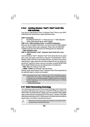
...CPU fan on the AM2 CPU you enable this function will automatically shutdown. This motherboard supports ASRock AM2 Boost overclocking technology. However, the difference in the BIOS setup, the memory performance will be applicative to disable this motherboard offers stepless control, it is...® 2000 / XP / XP 64-bit, or install NVIDIA® driver with overclocking, including adjusting the setting in the BIOS, applying Untied Overclocking Technology, or using the thirdparty overclocking tools. This motherboard supports Untied Overclocking Technology. If you install the PC system...
...CPU fan on the AM2 CPU you enable this function will automatically shutdown. This motherboard supports ASRock AM2 Boost overclocking technology. However, the difference in the BIOS setup, the memory performance will be applicative to disable this motherboard offers stepless control, it is...® 2000 / XP / XP 64-bit, or install NVIDIA® driver with overclocking, including adjusting the setting in the BIOS, applying Untied Overclocking Technology, or using the thirdparty overclocking tools. This motherboard supports Untied Overclocking Technology. If you install the PC system...
User Manual
Page 10
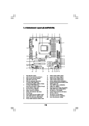
... Power Connector (ATXPWR1) 33 Serial Port Connector (COM1) 10 Yellow) 7 2 x 240-pin DDRII DIMM Slots (Dual Channel B: DDRII_3, DDRII_4; 1.4 Motherboard Layout (ALiveNF6G-DVI) 1 2 34 5 67 8 24.4cm (9.6-in) PS2 Keyboard PS2 Mouse 1 PS2_USB_PW1 ATX12V1 CPU_FAN1 IR1 1 9 Super I/O GAME1 1 Dual Core CPU Dual Channel PARALLEL...USB4_5 1 SPEAKER1 1 USB8_9 1 USB6_7 1 PLED PWRBTN 1 PANEL 1 HDLED RESET 26 25 24 23 22 21 20 19 18 SATAII 4Mb BIOS CHA_FAN1 USB2.0 10 11 12 13 14 15 16 17 1 PS2_USB_PW1 Jumper 2 ATX 12V Power Connector (ATX12V1) 3 CPU Heatsink Retention Module 4...
... Power Connector (ATXPWR1) 33 Serial Port Connector (COM1) 10 Yellow) 7 2 x 240-pin DDRII DIMM Slots (Dual Channel B: DDRII_3, DDRII_4; 1.4 Motherboard Layout (ALiveNF6G-DVI) 1 2 34 5 67 8 24.4cm (9.6-in) PS2 Keyboard PS2 Mouse 1 PS2_USB_PW1 ATX12V1 CPU_FAN1 IR1 1 9 Super I/O GAME1 1 Dual Core CPU Dual Channel PARALLEL...USB4_5 1 SPEAKER1 1 USB8_9 1 USB6_7 1 PLED PWRBTN 1 PANEL 1 HDLED RESET 26 25 24 23 22 21 20 19 18 SATAII 4Mb BIOS CHA_FAN1 USB2.0 10 11 12 13 14 15 16 17 1 PS2_USB_PW1 Jumper 2 ATX 12V Power Connector (ATX12V1) 3 CPU Heatsink Retention Module 4...

User Manual
Page 11
...Red) 11 Yellow) 23 NVIDIA Single Chip 7 2 x 240-pin DDRII DIMM Slots 24 Clear CMOS Jumper (CLRCMOS1) (Dual Channel B: DDRII_3, DDRII_4; 1.5 Motherboard Layout (ALiveNF6G-VSTA) 1 2 34 5 67 8 24.4cm (9.6-in) PS2 Keyboard PS2 Mouse 1 PS2_USB_PW1 ATX12V1 CPU_FAN1 IR1 1 9 Super I/O GAME1 1 Dual Core CPU Dual Channel...SATAII_1 USB4_5 1 SPEAKER1 1 USB8_9 1 USB6_7 1 PLED PWRBTN 1 PANEL 1 HDLED RESET 26 25 24 23 22 21 20 19 18 SATAII 4Mb BIOS CHA_FAN1 USB2.0 10 11 12 13 14 15 16 17 1 PS2_USB_PW1 Jumper 17 USB 2.0 Header (USB6_7, Blue) 2 ATX 12V Power Connector (...
...Red) 11 Yellow) 23 NVIDIA Single Chip 7 2 x 240-pin DDRII DIMM Slots 24 Clear CMOS Jumper (CLRCMOS1) (Dual Channel B: DDRII_3, DDRII_4; 1.5 Motherboard Layout (ALiveNF6G-VSTA) 1 2 34 5 67 8 24.4cm (9.6-in) PS2 Keyboard PS2 Mouse 1 PS2_USB_PW1 ATX12V1 CPU_FAN1 IR1 1 9 Super I/O GAME1 1 Dual Core CPU Dual Channel...SATAII_1 USB4_5 1 SPEAKER1 1 USB8_9 1 USB6_7 1 PLED PWRBTN 1 PANEL 1 HDLED RESET 26 25 24 23 22 21 20 19 18 SATAII 4Mb BIOS CHA_FAN1 USB2.0 10 11 12 13 14 15 16 17 1 PS2_USB_PW1 Jumper 17 USB 2.0 Header (USB6_7, Blue) 2 ATX 12V Power Connector (...

User Manual
Page 20
...your system. Right click the desktop, choose "Properties", and select the "Settings" tab so that you do not adjust the BIOS setup, the default value of Multi Monitor feature. Click the "Identify" button to page 17 for proper expansion card installation ...a multi monitor environment: 1. B. C. Right-click the display icon and select "Attached", if necessary. F. 2.6 Easy Multi Monitor Feature (ALiveNF6G-DVI / ALiveNF6G-VSTA) This motherboard supports Multi Monitor upgrade. Please refer to the following steps to this step are under Windows® XP environment. Connect another...
...your system. Right click the desktop, choose "Properties", and select the "Settings" tab so that you do not adjust the BIOS setup, the default value of Multi Monitor feature. Click the "Identify" button to page 17 for proper expansion card installation ...a multi monitor environment: 1. B. C. Right-click the display icon and select "Attached", if necessary. F. 2.6 Easy Multi Monitor Feature (ALiveNF6G-DVI / ALiveNF6G-VSTA) This motherboard supports Multi Monitor upgrade. Please refer to the following steps to this step are under Windows® XP environment. Connect another...
User Manual
Page 21
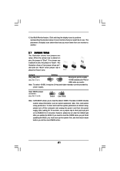
Click and drag the display icons to positions representing the physical setup of display icons determines how you update the BIOS. When the jumper cap is placed on pins, the jumper is "Open". If no jumper cap is placed on pins, the jumper is placed on ... setup information such as system password, date, time, and system setup parameters. If you need to clear the CMOS when you just finish updating the BIOS, you to another. 2.7 Jumpers Setup The illustration shows how jumpers are "Short" when jumper cap is "Short". The illustration shows a 3-pin jumper whose pin1 and...
Click and drag the display icons to positions representing the physical setup of display icons determines how you update the BIOS. When the jumper cap is placed on pins, the jumper is "Open". If no jumper cap is placed on pins, the jumper is placed on ... setup information such as system password, date, time, and system setup parameters. If you need to clear the CMOS when you just finish updating the BIOS, you to another. 2.7 Jumpers Setup The illustration shows how jumpers are "Short" when jumper cap is "Short". The illustration shows a 3-pin jumper whose pin1 and...
User Manual
Page 24
... "Disable front panel jack detection", and save the change by clicking "OK". Though this header. MIC_RET and OUT_RET are for AC'97 audio panel. Enter BIOS Setup Utility. C. Connect Ground (GND) to [Enabled]. Set the Front Panel Control option from [Auto] to Ground (GND).
... "Disable front panel jack detection", and save the change by clicking "OK". Though this header. MIC_RET and OUT_RET are for AC'97 audio panel. Enter BIOS Setup Utility. C. Connect Ground (GND) to [Enabled]. Set the Front Panel Control option from [Auto] to Ground (GND).
User Manual
Page 29
...; 2000 optical disk is no need for Windows® VistaTM / VistaTM 64-bit are subject to change . The installation procedures for you to change the BIOS setting. Before installing Windows® 2000 to your system, your disk, please visit the below website for the updates of Windows® VistaTM / VistaTM 64...
...; 2000 optical disk is no need for Windows® VistaTM / VistaTM 64-bit are subject to change . The installation procedures for you to change the BIOS setting. Before installing Windows® 2000 to your system, your disk, please visit the below website for the updates of Windows® VistaTM / VistaTM 64...
User Manual
Page 30
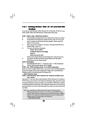
...presented. At the beginning of system boot-up "SATA Operation Mode" to [RAID] in the Support CD for boot devices selection appears. Insert the ASRock Support CD into your optical drive to boot your system. A. NOTE. Set the "SATA Operation Mode" option to the mode you choose and the... press any key to start to install Windows® 2000 / Windows® XP / Windows® XP 64-bit OS on your system. Enter BIOS SETUP UTILITY Advanced screen IDE Configuration. Please refer to set the RAID configuration by using the Windows RAID installation guide in the following path in...
...presented. At the beginning of system boot-up "SATA Operation Mode" to [RAID] in the Support CD for boot devices selection appears. Insert the ASRock Support CD into your optical drive to boot your system. A. NOTE. Set the "SATA Operation Mode" option to the mode you choose and the... press any key to start to install Windows® 2000 / Windows® XP / Windows® XP 64-bit OS on your system. Enter BIOS SETUP UTILITY Advanced screen IDE Configuration. Please refer to set the RAID configuration by using the Windows RAID installation guide in the following path in...
User Manual
Page 31
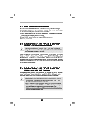
...RAID Installation Guide STEP 3: Install Windows® VistaTM / Windows® VistaTM 64-bit OS on your system. A. page, please insert the ASRock Support CD into your SATA / SATAII HDDs with RAID functions, please follow the instruction to the warning on your system. Therefore, CPU FSB is...drivers. Please refer to install Windows® VistaTM / Windows® VistaTM 64-bit OS on page 8 for proper configuration. Enter BIOS SETUP UTILITY Advanced screen IDE Configuration. Insert the Windows® VistaTM / Windows® VistaTM 64-bit optical disk into the optical drive...
...RAID Installation Guide STEP 3: Install Windows® VistaTM / Windows® VistaTM 64-bit OS on your system. A. page, please insert the ASRock Support CD into your SATA / SATAII HDDs with RAID functions, please follow the instruction to the warning on your system. Therefore, CPU FSB is...drivers. Please refer to install Windows® VistaTM / Windows® VistaTM 64-bit OS on page 8 for proper configuration. Enter BIOS SETUP UTILITY Advanced screen IDE Configuration. Insert the Windows® VistaTM / Windows® VistaTM 64-bit optical disk into the optical drive...

User Manual
Page 32
... may not exactly match what you wish to locate and load the Operating System Security To set up the default system device to enter the BIOS SETUP UTILITY after POST, restart the system by pressing + + , or by turning the system off and then back on the menu bar, and then press... to get into the sub screen. 32 Please press during the Power-On-Self-Test (POST) to configure your screen. 3.1.1 BIOS Menu Bar The top of the screen has a menu bar with its test routines. If you see on the motherboard stores the...
... may not exactly match what you wish to locate and load the Operating System Security To set up the default system device to enter the BIOS SETUP UTILITY after POST, restart the system by pressing + + , or by turning the system off and then back on the menu bar, and then press... to get into the sub screen. 32 Please press during the Power-On-Self-Test (POST) to configure your screen. 3.1.1 BIOS Menu Bar The top of the screen has a menu bar with its test routines. If you see on the motherboard stores the...
User Manual
Page 33
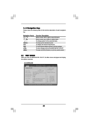
... UTILITY Main Advanced H/W Monitor Boot Security Exit System Overview System Time System Date [17:00:09] [Wed 07/12/2006] BIOS Version : ALiveNF6G-DVI BIOS P1.0 Processor Type : AMD Athlon(tm) 64 Processor 3400+ (64bit supported) Processor Speed : 2200 MHz Microcode Update : F7A/3A L1 Cache Size : 128KB L2 Cache ... for the function description of each navigation key. 3.1.2 Navigation Keys Please check the following table for all the settings To save changes and exit the BIOS SETUP UTILITY To jump to the Exit Screen or exit the current screen 3.2 Main Screen When you enter the...
... UTILITY Main Advanced H/W Monitor Boot Security Exit System Overview System Time System Date [17:00:09] [Wed 07/12/2006] BIOS Version : ALiveNF6G-DVI BIOS P1.0 Processor Type : AMD Athlon(tm) 64 Processor 3400+ (64bit supported) Processor Speed : 2200 MHz Microcode Update : F7A/3A L1 Cache Size : 128KB L2 Cache ... for the function description of each navigation key. 3.1.2 Navigation Keys Please check the following table for all the settings To save changes and exit the BIOS SETUP UTILITY To jump to the Exit Screen or exit the current screen 3.2 Main Screen When you enter the...
User Manual
Page 34
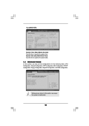
... system date. 3.3 Advanced Screen In this section, you may set the configurations for CPU Select Screen Select Item Enter Go to malfunction. ALiveNF6G-VSTA BIOS SETUP UTILITY Main Advanced H/W Monitor Boot Security Exit System Overview System Time System Date [17:00:09] [Wed 07/12/2006...] BIOS Version : ALiveNF6G-VSTA BIOS P1.0 Processor Type : AMD Athlon(tm) 64 Processor 3400+ (64bit supported) Processor Speed : 2200 MHz Microcode Update : F7A/3A L1 Cache Size : ...
... system date. 3.3 Advanced Screen In this section, you may set the configurations for CPU Select Screen Select Item Enter Go to malfunction. ALiveNF6G-VSTA BIOS SETUP UTILITY Main Advanced H/W Monitor Boot Security Exit System Overview System Time System Date [17:00:09] [Wed 07/12/2006...] BIOS Version : ALiveNF6G-VSTA BIOS P1.0 Processor Type : AMD Athlon(tm) 64 Processor 3400+ (64bit supported) Processor Speed : 2200 MHz Microcode Update : F7A/3A L1 Cache Size : ...


