
User Manual
Page 5
... better performance in Windows® 7 / 7 64-bit / VistaTM / VistaTM 64 bit, it is recommended to set the BIOS option in , 22.6 cm x 21.6 cm) ASRock A75M-HVS Quick Installation Guide ASRock A75M-HVS Support CD 2 x Serial ATA (SATA) Data Cables (Optional) 1 x I/O Panel Shield ASRock Reminds You... You may nd the latest VGA cards and CPU support lists on...
... better performance in Windows® 7 / 7 64-bit / VistaTM / VistaTM 64 bit, it is recommended to set the BIOS option in , 22.6 cm x 21.6 cm) ASRock A75M-HVS Quick Installation Guide ASRock A75M-HVS Support CD 2 x Serial ATA (SATA) Data Cables (Optional) 1 x I/O Panel Shield ASRock Reminds You... You may nd the latest VGA cards and CPU support lists on...

User Manual
Page 7
... header - 1 x COM port header - Front panel audio connector - 3 x USB 2.0 headers (support 6 USB 2.0 ports) - 32Mb AMI UEFI Legal BIOS with LED (ACT/LINK LED and SPEED LED) - ASRock Extreme Tuning Utility (AXTU) (see CAUTION 10) 7 ASRock XFast USB (see CAUTION 6) - CPU/Chassis/Power FAN connector - 24 pin ATX power connector - 8 pin 12V power connector...
... header - 1 x COM port header - Front panel audio connector - 3 x USB 2.0 headers (support 6 USB 2.0 ports) - 32Mb AMI UEFI Legal BIOS with LED (ACT/LINK LED and SPEED LED) - ASRock Extreme Tuning Utility (AXTU) (see CAUTION 10) 7 ASRock XFast USB (see CAUTION 6) - CPU/Chassis/Power FAN connector - 24 pin ATX power connector - 8 pin 12V power connector...

User Manual
Page 8
...caused by overclocking. 8 Chassis Temperature Sensing - CPU Temperature Sensing Monitor - ASRock U-COP (see CAUTION 12) * For detailed product information, please visit our website: http://www.asrock.com WARNING Please realize that there is a certain risk involved with overclocking, ...including adjusting the setting in the BIOS, applying Untied Overclocking Technology, or using the third-party overclocking tools....
...caused by overclocking. 8 Chassis Temperature Sensing - CPU Temperature Sensing Monitor - ASRock U-COP (see CAUTION 12) * For detailed product information, please visit our website: http://www.asrock.com WARNING Please realize that there is a certain risk involved with overclocking, ...including adjusting the setting in the BIOS, applying Untied Overclocking Technology, or using the third-party overclocking tools....

User Manual
Page 9
...®. In Hardware Monitor, it shows the fan speed and temperature for the latest information. 5. ASRock Extreme Tuning Utility (AXTU) is an all-in a user-friendly interface, which is a BIOS ash utility embedded in EDID. Please visit our website for proper installation. 2. This motherboard supports Dual... the number of memory modules on the CPU you to access ASRock Instant Flash. With this tool and save the new BIOS le to your system. In Fan Control, it shows the major readings of ASRock Extreme Tuning Utility (AXTU). Due to improve efficiency when the CPU...
...®. In Hardware Monitor, it shows the fan speed and temperature for the latest information. 5. ASRock Extreme Tuning Utility (AXTU) is an all-in a user-friendly interface, which is a BIOS ash utility embedded in EDID. Please visit our website for proper installation. 2. This motherboard supports Dual... the number of memory modules on the CPU you to access ASRock Instant Flash. With this tool and save the new BIOS le to your system. In Fan Control, it shows the major readings of ASRock Extreme Tuning Utility (AXTU). Due to improve efficiency when the CPU...

User Manual
Page 11
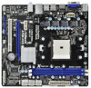
... B: USB3 USB 3.0 T: USB4 B: USB5 USB 2.0 T: USB0 B: USB1 LAN AUDIO CODEC RJ-45 LAN RoHS Dual Graphics ErP/EuP Ready SATA3 6Gb/s USB 3.0 PWR_FAN1 32Mb BIOS PCIE1 A75M-HVS PCIE2 AMD A75 FCH (Hudson-D3) Chipset PCI1 CMOS BATTERY XFast USB Super I/O Designed in Taipei HD_AUDIO1 1 USB10_11 1 USB8_9 1 USB6_7 1 1 CIR1 IR1 1 CHA_FAN1 CLRCMOS1 PANEL...
... B: USB3 USB 3.0 T: USB4 B: USB5 USB 2.0 T: USB0 B: USB1 LAN AUDIO CODEC RJ-45 LAN RoHS Dual Graphics ErP/EuP Ready SATA3 6Gb/s USB 3.0 PWR_FAN1 32Mb BIOS PCIE1 A75M-HVS PCIE2 AMD A75 FCH (Hudson-D3) Chipset PCI1 CMOS BATTERY XFast USB Super I/O Designed in Taipei HD_AUDIO1 1 USB10_11 1 USB8_9 1 USB6_7 1 1 CIR1 IR1 1 CHA_FAN1 CLRCMOS1 PANEL...

User Manual
Page 23
... Jumper (CLRCMOS1) (see p.11, No. 18) Setting Default Clear CMOS Description Note: CLRCMOS1 allows you to clear the CMOS when you just nish updating the BIOS, you must boot up the system rst, and then shut it down before you do not clear the CMOS right after you need to clear... the data in CMOS. If you update the BIOS. When the jumper cap is placed on CLRCMOS1 for 15 seconds, use a jumper cap to default setup, please turn off the computer and unplug the...
... Jumper (CLRCMOS1) (see p.11, No. 18) Setting Default Clear CMOS Description Note: CLRCMOS1 allows you to clear the CMOS when you just nish updating the BIOS, you must boot up the system rst, and then shut it down before you do not clear the CMOS right after you need to clear... the data in CMOS. If you update the BIOS. When the jumper cap is placed on CLRCMOS1 for 15 seconds, use a jumper cap to default setup, please turn off the computer and unplug the...

User Manual
Page 32
... diskette by following section 2.14.1 step 2 on your system. 32 Before you start to con gure RAID function, you want to the BIOS RAID installation guide part of the document in the following path in the Support CD for proper con guration. Before you need to check the...Windows® 7 / 7 64-bit / VistaTM / VistaTM 64-bit OS on your system. At the beginning of Windows® setup, press F6 to the BIOS RAID installation guide part of 2 or more SATA3 HDDs with RAID functions, please follow below steps. Enter UEFI SETUP UTILITY Advanced screen Storage Con guration...
... diskette by following section 2.14.1 step 2 on your system. 32 Before you start to con gure RAID function, you want to the BIOS RAID installation guide part of the document in the following path in the Support CD for proper con guration. Before you need to check the...Windows® 7 / 7 64-bit / VistaTM / VistaTM 64-bit OS on your system. At the beginning of Windows® setup, press F6 to the BIOS RAID installation guide part of 2 or more SATA3 HDDs with RAID functions, please follow below steps. Enter UEFI SETUP UTILITY Advanced screen Storage Con guration...

User Manual
Page 54
... Con guration > SATA Mode. 3. Installing OS on a large size HDD (>2TB). Set AHCI Mode in UEFI Setup Utility > Boot > Boot Option #1. ("xxx" is adopting UEFI BIOS that allows Windows® OS to be installed on a HDD Larger Than 2TB This motherboard is the device which contains your Windows® installation les...
... Con guration > SATA Mode. 3. Installing OS on a large size HDD (>2TB). Set AHCI Mode in UEFI Setup Utility > Boot > Boot Option #1. ("xxx" is adopting UEFI BIOS that allows Windows® OS to be installed on a HDD Larger Than 2TB This motherboard is the device which contains your Windows® installation les...

Quick Installation Guide
Page 2
...USB 3.0 T: USB4 B: USB5 USB 2.0 T: USB0 B: USB1 LAN AUDIO CODEC RJ-45 LAN RoHS Dual Graphics ErP/EuP Ready SATA3 6Gb/s USB 3.0 PWR_FAN1 32Mb BIOS PCIE1 A75M-HVS PCIE2 AMD A75 FCH (Hudson-D3) Chipset PCI1 CMOS BATTERY XFast USB Super I/O Designed in Taipei HD_AUDIO1 1 USB10_11 1 USB8_9 1 USB6_7 1 1 CIR1 IR1 1 CHA_FAN1... 1, White) 29 SPI Flash Memory (32Mb) 14 Southbridge Controller 30 Power Fan Connector (PWR_FAN1) 15 Print Port Header (LPT1, White) English 2 ASRock A75M-HVS Motherboard Blue) 12 SATA3 Connector (SATA_1, White) 28 PCI Express 2.0 x1 Slot (PCIE1;
...USB 3.0 T: USB4 B: USB5 USB 2.0 T: USB0 B: USB1 LAN AUDIO CODEC RJ-45 LAN RoHS Dual Graphics ErP/EuP Ready SATA3 6Gb/s USB 3.0 PWR_FAN1 32Mb BIOS PCIE1 A75M-HVS PCIE2 AMD A75 FCH (Hudson-D3) Chipset PCI1 CMOS BATTERY XFast USB Super I/O Designed in Taipei HD_AUDIO1 1 USB10_11 1 USB8_9 1 USB6_7 1 1 CIR1 IR1 1 CHA_FAN1... 1, White) 29 SPI Flash Memory (32Mb) 14 Southbridge Controller 30 Power Fan Connector (PWR_FAN1) 15 Print Port Header (LPT1, White) English 2 ASRock A75M-HVS Motherboard Blue) 12 SATA3 Connector (SATA_1, White) 28 PCI Express 2.0 x1 Slot (PCIE1;

Quick Installation Guide
Page 4
...; 7 / 7 64-bit / VistaTM / VistaTM 64bit, it is recommended to set the BIOS option in Storage Configuration to the "User Manual" in , 22.6 cm x 21.6 cm) ASRock A75M-HVS Quick Installation Guide ASRock A75M-HVS Support CD 2 x Serial ATA (SATA) Data Cables (Optional) 1 x I/O Panel Shield ASRock Reminds You... You may find the latest VGA cards and...
...; 7 / 7 64-bit / VistaTM / VistaTM 64bit, it is recommended to set the BIOS option in Storage Configuration to the "User Manual" in , 22.6 cm x 21.6 cm) ASRock A75M-HVS Quick Installation Guide ASRock A75M-HVS Support CD 2 x Serial ATA (SATA) Data Cables (Optional) 1 x I/O Panel Shield ASRock Reminds You... You may find the latest VGA cards and...

Quick Installation Guide
Page 6
... (support 6 USB 2.0 ports) - 32Mb AMI UEFI Legal BIOS with LED (ACT/LINK LED and SPEED LED) - Supports jumperfree - ASRock Extreme Tuning Utility (AXTU) (see CAUTION 9) - ASRock SmartView (see CAUTION 6) - ASRock XFast USB (see CAUTION 8) - Supports "Plug and Play" - OEM and Trial) - ASRock APP Charger (see CAUTION 10) ASRock A75M-HVS Motherboard HD Audio Jack: Line in/Front Speaker...
... (support 6 USB 2.0 ports) - 32Mb AMI UEFI Legal BIOS with LED (ACT/LINK LED and SPEED LED) - Supports jumperfree - ASRock Extreme Tuning Utility (AXTU) (see CAUTION 9) - ASRock SmartView (see CAUTION 6) - ASRock XFast USB (see CAUTION 8) - Supports "Plug and Play" - OEM and Trial) - ASRock APP Charger (see CAUTION 10) ASRock A75M-HVS Motherboard HD Audio Jack: Line in/Front Speaker...

Quick Installation Guide
Page 7
...: +12V, +5V, +3.3V, Vcore OS - CPU/Chassis Quiet Fan - FCC, CE, WHQL - Chassis Temperature Sensing - English 7 ASRock A75M-HVS Motherboard CPU Temperature Sensing Monitor - Overclocking may affect your system stability, or even cause damage to the components and devices of your own risk and... expense. ASRock U-COP (see CAUTION 12) * For detailed product information, please visit our website: http://www.asrock.com WARNING Please realize that there is a certain risk involved with overclocking, including...
...: +12V, +5V, +3.3V, Vcore OS - CPU/Chassis Quiet Fan - FCC, CE, WHQL - Chassis Temperature Sensing - English 7 ASRock A75M-HVS Motherboard CPU Temperature Sensing Monitor - Overclocking may affect your system stability, or even cause damage to the components and devices of your own risk and... expense. ASRock U-COP (see CAUTION 12) * For detailed product information, please visit our website: http://www.asrock.com WARNING Please realize that there is a certain risk involved with overclocking, including...

Quick Installation Guide
Page 8
... output phases to update system BIOS without sacrificing computing performance. Deep Color mode will be noted that the USB flash drive or hard drive must use FAT32/16/12 file system. 8 ASRock A75M-HVS Motherboard English ASRock Extreme Tuning Utility (AXTU) is... including Hardware Monitor, Fan Control and IES. ASRock website: http://www.asrock.com 7. ASRock website http://www.asrock.com 3. This motherboard supports Dual Channel Memory Technology. For ...
... output phases to update system BIOS without sacrificing computing performance. Deep Color mode will be noted that the USB flash drive or hard drive must use FAT32/16/12 file system. 8 ASRock A75M-HVS Motherboard English ASRock Extreme Tuning Utility (AXTU) is... including Hardware Monitor, Fan Control and IES. ASRock website: http://www.asrock.com 7. ASRock website http://www.asrock.com 3. This motherboard supports Dual Channel Memory Technology. For ...

Quick Installation Guide
Page 20
... Note: CLRCMOS1 allows you to default setup, please turn off the computer and unplug the power cord from the power supply. If you update the BIOS. After waiting for 15 seconds, use a jumper cap to clear the CMOS when you just finish updating the... BIOS, you must boot up the system first, and then shut it down before you do not clear the CMOS right after you need to short pin2 and pin3 on CLRCMOS1 for 5 seconds. When the jumper cap is placed on pins, the jumper is removed. English 20 ASRock A75M-HVS Motherboard
... Note: CLRCMOS1 allows you to default setup, please turn off the computer and unplug the power cord from the power supply. If you update the BIOS. After waiting for 15 seconds, use a jumper cap to clear the CMOS when you just finish updating the... BIOS, you must boot up the system first, and then shut it down before you do not clear the CMOS right after you need to short pin2 and pin3 on CLRCMOS1 for 5 seconds. When the jumper cap is placed on pins, the jumper is removed. English 20 ASRock A75M-HVS Motherboard

Quick Installation Guide
Page 27
...features. otherwise, POST continues with the motherboard contains necessary drivers and useful utilities that came with its various sub-menus and to enter BIOS Setup after POST, please restart the system by pressing + + , or pressing the reset button on the system chassis. Software ...to scroll through its test routines. It is enabled in the Support CD. 4. For the detailed information about BIOS Setup, please refer to display the menus. 27 ASRock A75M-HVS Motherboard English The Support CD that will display the Main Menu automatically if "AUTORUN" is a menu-driven program...
...features. otherwise, POST continues with the motherboard contains necessary drivers and useful utilities that came with its various sub-menus and to enter BIOS Setup after POST, please restart the system by pressing + + , or pressing the reset button on the system chassis. Software ...to scroll through its test routines. It is enabled in the Support CD. 4. For the detailed information about BIOS Setup, please refer to display the menus. 27 ASRock A75M-HVS Motherboard English The Support CD that will display the Main Menu automatically if "AUTORUN" is a menu-driven program...
Quick Installation Guide
Page 153
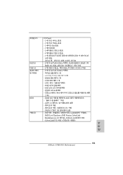
... USB 2.0 헤더 3 개 (6 USB 2.0 2개 ) - 32Mb GUI AMI UEFI 적합형 BIOS ACPI 1.1 SMBIOS 2.3.1 지원 - Explorer, AMD Fusion, CyberLink MediaEspresso 6.5 ASRock CyberLink DVD 세트 ) (OEM 한 국 어 153 ASRock A75M-HVS Motherboard 후면판 I/O SATA3 USB 3.0 BIOS 지원 CD I/O Panel - 1 개 PS/2 1 개 PS/2 1 개의 D-Sub 포트...
... USB 2.0 헤더 3 개 (6 USB 2.0 2개 ) - 32Mb GUI AMI UEFI 적합형 BIOS ACPI 1.1 SMBIOS 2.3.1 지원 - Explorer, AMD Fusion, CyberLink MediaEspresso 6.5 ASRock CyberLink DVD 세트 ) (OEM 한 국 어 153 ASRock A75M-HVS Motherboard 후면판 I/O SATA3 USB 3.0 BIOS 지원 CD I/O Panel - 1 개 PS/2 1 개 PS/2 1 개의 D-Sub 포트...

Quick Installation Guide
Page 154
...;의 8 참조 ) - CPU 계 - FCC, CE, WHQL - ErP/EuP 지원 (ErP/EuP ( 주의 12 참조 ) http://www.asrock.com BIOS Untied Overclocking Technology 한 국 어 154 ASRock A75M-HVS Motherboard CPU - CPU 12V,+5V,+3.3V,Vcore OS Windows® 7/7 64 비트 /VistaTM/ VistaTM 64 비트 /XP SP3/XP...
...;의 8 참조 ) - CPU 계 - FCC, CE, WHQL - ErP/EuP 지원 (ErP/EuP ( 주의 12 참조 ) http://www.asrock.com BIOS Untied Overclocking Technology 한 국 어 154 ASRock A75M-HVS Motherboard CPU - CPU 12V,+5V,+3.3V,Vcore OS Windows® 7/7 64 비트 /VistaTM/ VistaTM 64 비트 /XP SP3/XP...

Quick Installation Guide
Page 163
2.7 3 1-2 점퍼 CMOS 초기화 (CLRCMOS1, 3 2 18 세팅 CMOS 삭제 참고 : CLRCMOS1 CMOS 15 CLRCMOS1 의 핀 2 와 핀 3 을 5 BIOS CMOS BIOS CMOS CMOS CMOS 1394 GUID, MAC 한국어 163 ASRock A75M-HVS Motherboard
2.7 3 1-2 점퍼 CMOS 초기화 (CLRCMOS1, 3 2 18 세팅 CMOS 삭제 참고 : CLRCMOS1 CMOS 15 CLRCMOS1 의 핀 2 와 핀 3 을 5 BIOS CMOS BIOS CMOS CMOS CMOS 1394 GUID, MAC 한국어 163 ASRock A75M-HVS Motherboard

Quick Installation Guide
Page 174
...;照 ) - I /O Panel - Ready-to -Use USB 2.0 ポート x 2 - ASRock ASRock Instant Flash ( 注意 7 参照 ) - PS/2 x 1 - ASRock APP 8 を参照 ) 日本語 174 ASRock A75M-HVS Motherboard PS/2 x 1 - D-Sub ポート x 1 - HDMI ポート x ...に最高 5Gb/s 6 x SATA3 6.0Gb IR x 1 x 1 x 1 - PXE I /O SATA3 USB 3.0 BIOS CD 特徴 - CPU 24 ピン ATX 8 ピン 12V USB 2.0 USB 2.0 用 6 x 3 - 32Mb AMI UEFI Legal...
...;照 ) - I /O Panel - Ready-to -Use USB 2.0 ポート x 2 - ASRock ASRock Instant Flash ( 注意 7 参照 ) - PS/2 x 1 - ASRock APP 8 を参照 ) 日本語 174 ASRock A75M-HVS Motherboard PS/2 x 1 - D-Sub ポート x 1 - HDMI ポート x ...に最高 5Gb/s 6 x SATA3 6.0Gb IR x 1 x 1 x 1 - PXE I /O SATA3 USB 3.0 BIOS CD 特徴 - CPU 24 ピン ATX 8 ピン 12V USB 2.0 USB 2.0 用 6 x 3 - 32Mb AMI UEFI Legal...

Quick Installation Guide
Page 184
2.7 1-2 CMOS CLRCMOS1 18 参照) 設定 説明 CMOS の消去 注 : CLRCMOS1 CMOS 15 CLRCMOS1 のピン 2 とピン 3 を 5 BIOS CMOS BIOS CMOS CMOS 1394 GUID と MAC CMOS 日本語 184 ASRock A75M-HVS Motherboard
2.7 1-2 CMOS CLRCMOS1 18 参照) 設定 説明 CMOS の消去 注 : CLRCMOS1 CMOS 15 CLRCMOS1 のピン 2 とピン 3 を 5 BIOS CMOS BIOS CMOS CMOS 1394 GUID と MAC CMOS 日本語 184 ASRock A75M-HVS Motherboard


