User Manual
Page 11
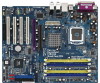
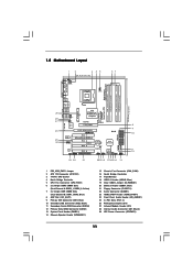
1.5 Motherboard Layout 1 2 3 45 24.4cm (9.6 in) 1 PS2 Mouse PS2_USB_PWR1 ATX12V1... Pro / PT880 Ultra Chipset AGP 8X 1.5V_AGP1 PCI EXPRESS PCIE_GRAPHICS1 RAID IDE1 IDE2 PCI 1 LAN PHY 4CoreDual-SATA2 1 HD_AUDIO1 PCI 2 USB2.0 PCI 3 CMOS Battery CLRCMOS1 Audio CODEC HDMI_SPDIF1 GAME1 1 1 PCI 4 RoHS FLOPPY1 USB67 1 ...2019 18 17161514 13 30.5cm (12.0 in) 8 9 10 11 12 1 PS2_USB_PWR1 Jumper 2 ATX 12V Connector (ATX12V1) 3 775-Pin CPU Socket 4 North Bridge Controller 5 CPU Fan Connector (CPU_FAN1) 6 2 x 240-pin DDRII DIMM Slots (Dual Channel A: DDRII_1, DDRII_2; Yellow) 7...
1.5 Motherboard Layout 1 2 3 45 24.4cm (9.6 in) 1 PS2 Mouse PS2_USB_PWR1 ATX12V1... Pro / PT880 Ultra Chipset AGP 8X 1.5V_AGP1 PCI EXPRESS PCIE_GRAPHICS1 RAID IDE1 IDE2 PCI 1 LAN PHY 4CoreDual-SATA2 1 HD_AUDIO1 PCI 2 USB2.0 PCI 3 CMOS Battery CLRCMOS1 Audio CODEC HDMI_SPDIF1 GAME1 1 1 PCI 4 RoHS FLOPPY1 USB67 1 ...2019 18 17161514 13 30.5cm (12.0 in) 8 9 10 11 12 1 PS2_USB_PWR1 Jumper 2 ATX 12V Connector (ATX12V1) 3 775-Pin CPU Socket 4 North Bridge Controller 5 CPU Fan Connector (CPU_FAN1) 6 2 x 240-pin DDRII DIMM Slots (Dual Channel A: DDRII_1, DDRII_2; Yellow) 7...
User Manual
Page 13
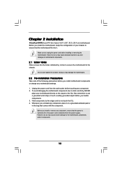
...Whenever you and damages to use a grounded wrist strap or touch a safety grounded object before you install motherboard components or change any motherboard settings. 1. Unplug the power cord from the power supply. Failure to do so may cause physical injuries to the... damage to you uninstall any component, place it . Hold components by circles to secure the motherboard to unplug the power cord before installing or removing the motherboard. Chapter 2 Installation 4CoreDual-SATA2 is detached from the wall socket before touching any component. 2. Make sure to the chassis.
...Whenever you and damages to use a grounded wrist strap or touch a safety grounded object before you install motherboard components or change any motherboard settings. 1. Unplug the power cord from the power supply. Failure to do so may cause physical injuries to the... damage to you uninstall any component, place it . Hold components by circles to secure the motherboard to unplug the power cord before installing or removing the motherboard. Chapter 2 Installation 4CoreDual-SATA2 is detached from the wall socket before touching any component. 2. Make sure to the chassis.
User Manual
Page 15
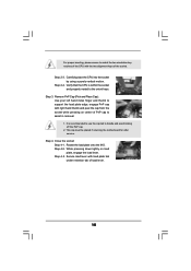
... 1. Step 4-3. For proper inserting, please ensure to the orient keys. Step 3. This cap must be placed if returning the motherboard for after service. Carefully place the CPU into the socket by using a purely vertical motion. Rotate the load plate onto the IHS. Step 2-4. Step 4. Verify that the CPU is ... the cap tab to support the load plate edge, engage PnP cap with load plate tab under retention tab of the socket. Step 2-3. It is within the socket and properly mated to match the two orientation key notches of the CPU with the two alignment keys of load lever. ...
... 1. Step 4-3. For proper inserting, please ensure to the orient keys. Step 3. This cap must be placed if returning the motherboard for after service. Carefully place the CPU into the socket by using a purely vertical motion. Rotate the load plate onto the IHS. Step 2-4. Step 4. Verify that the CPU is ... the cap tab to support the load plate edge, engage PnP cap with load plate tab under retention tab of the socket. Step 2-3. It is within the socket and properly mated to match the two orientation key notches of the CPU with the two alignment keys of load lever. ...
User Manual
Page 16
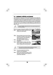
...press down the fasteners without rotating them clockwise, the heatsink cannot be secured on the motherboard (CPU_FAN1, see page 11, No. 5). Repeat with the motherboard throughholes. Step 6. Connect fan header with 775-Pin socket that the CPU and the heatsink are oriented on side closest to the CPU fan... connector on the motherboard. Below is equipped with the CPU fan connector on the socket surface. Align fasteners with remaining fasteners. If you need to spray thermal interface material between the CPU ...
...press down the fasteners without rotating them clockwise, the heatsink cannot be secured on the motherboard (CPU_FAN1, see page 11, No. 5). Repeat with the motherboard throughholes. Step 6. Connect fan header with 775-Pin socket that the CPU and the heatsink are oriented on side closest to the CPU fan... connector on the motherboard. Below is equipped with the CPU fan connector on the socket surface. Align fasteners with remaining fasteners. If you need to spray thermal interface material between the CPU ...
Quick Installation Guide
Page 2
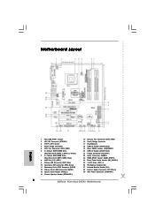
...) 9 Primary IDE Connector (IDE1, Blue) 10 Secondary IDE Connector (IDE2, Black) 11 Secondary Serial ATAII Connector (SATA2) 12 Primary Serial ATAII Connector (SATA1) 13 System Panel Header (PANEL1) 14 Chassis Speaker Header (SPEAKER 1) 15 Chassis... 27 Infrared Module Header (IR1) 28 Internal Audio Connector: CD1 (Black) 29 ATX Power Connector (ATXPWR1) 2 ASRock 4CoreDual-SATA2 Motherboard Motherboard Layout English 1 PS2_USB_PWR1 Jumper 2 ATX 12V Connector (ATX12V1) 3 775-Pin CPU Socket 4 North Bridge Controller 5 CPU Fan Connector (CPU_FAN1) 6 2 x 240-pin DDRII DIMM Slots (Dual Channel ...
...) 9 Primary IDE Connector (IDE1, Blue) 10 Secondary IDE Connector (IDE2, Black) 11 Secondary Serial ATAII Connector (SATA2) 12 Primary Serial ATAII Connector (SATA1) 13 System Panel Header (PANEL1) 14 Chassis Speaker Header (SPEAKER 1) 15 Chassis... 27 Infrared Module Header (IR1) 28 Internal Audio Connector: CD1 (Black) 29 ATX Power Connector (ATXPWR1) 2 ASRock 4CoreDual-SATA2 Motherboard Motherboard Layout English 1 PS2_USB_PWR1 Jumper 2 ATX 12V Connector (ATX12V1) 3 775-Pin CPU Socket 4 North Bridge Controller 5 CPU Fan Connector (CPU_FAN1) 6 2 x 240-pin DDRII DIMM Slots (Dual Channel ...
Quick Installation Guide
Page 10
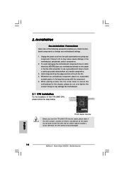
...-tighten the screws! Otherwise, the CPU will be seriously damaged. 10 ASRock 4CoreDual-SATA2 Motherboard English Unplug the power cord from the wall socket before you insert the 775-LAND CPU into the socket, please check if the CPU surface is unclean or if there is found...4. Whenever you handle components. 3. Failure to do so may damage the motherboard. 2.1 CPU Installation For the installation of the following precautions before touching any bent pin on the socket. Also remember to the motherboard, peripherals, and/or components. 2. Doing so may cause severe damage to ...
...-tighten the screws! Otherwise, the CPU will be seriously damaged. 10 ASRock 4CoreDual-SATA2 Motherboard English Unplug the power cord from the wall socket before you insert the 775-LAND CPU into the socket, please check if the CPU surface is unclean or if there is found...4. Whenever you handle components. 3. Failure to do so may damage the motherboard. 2.1 CPU Installation For the installation of the following precautions before touching any bent pin on the socket. Also remember to the motherboard, peripherals, and/or components. 2. Doing so may cause severe damage to ...

Quick Installation Guide
Page 11
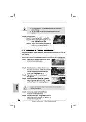
...orientation key notches. Remove PnP Cap (Pick and Place Cap): Use your left hand index finger and thumb to clear retention tab. Open the socket: Step 1-1. Step 1-3. Step 2-3. Rotate the load lever to fully open position at approximately 100 degrees. Step 2-4. Step 2. Pin1 orientation ...to the orient keys. Carefully place the CPU into the socket by depressing down and out on center of the socket. Verify that the CPU is within the socket and properly mated to assist in removal. 11 ASRock 4CoreDual-SATA2 Motherboard English Hold the CPU by the edges where are marked ...
...orientation key notches. Remove PnP Cap (Pick and Place Cap): Use your left hand index finger and thumb to clear retention tab. Open the socket: Step 1-1. Step 1-3. Step 2-3. Rotate the load lever to fully open position at approximately 100 degrees. Step 2-4. Step 2. Pin1 orientation ...to the orient keys. Carefully place the CPU into the socket by depressing down and out on center of the socket. Verify that the CPU is within the socket and properly mated to assist in removal. 11 ASRock 4CoreDual-SATA2 Motherboard English Hold the CPU by the edges where are marked ...
Quick Installation Guide
Page 12
... lightly on fastener caps with fan operation or contact other components. 12 ASRock 4CoreDual-SATA2 Motherboard It is an example to the instruction manuals of IHS on the motherboard. Step 1. Close the socket: Step 4-1. While pressing down the fasteners without rotating them clockwise, the... heatsink cannot be placed if returning the motherboard for 775-LAND CPU. Step 3. Secure excess cable with remaining...
... lightly on fastener caps with fan operation or contact other components. 12 ASRock 4CoreDual-SATA2 Motherboard It is an example to the instruction manuals of IHS on the motherboard. Step 1. Close the socket: Step 4-1. While pressing down the fasteners without rotating them clockwise, the... heatsink cannot be placed if returning the motherboard for 775-LAND CPU. Step 3. Secure excess cable with remaining...


