
Getting Started Guide
Page 1
DUA1770-0AAA05 Published September 2003 SuperStack® 3 Switch 4900 Family Getting Started Guide Switch 4900 (3C17700) Switch 4900 SX (3C17702) Switch 4924 (3C17701) Switch 4950 (3C17706) http://www.3com.com/ Part No.
DUA1770-0AAA05 Published September 2003 SuperStack® 3 Switch 4900 Family Getting Started Guide Switch 4900 (3C17700) Switch 4900 SX (3C17702) Switch 4924 (3C17701) Switch 4950 (3C17706) http://www.3com.com/ Part No.

Getting Started Guide
Page 3
CONTENTS ABOUT THIS GUIDE Conventions 8 Related Documentation 9 Accessing Online Documentation 9 Documentation Comments 10 1 INTRODUCING THE SUPERSTACK 3 SWITCH 4900 FAMILY About the Switches 12 Summary of Each Other 24 Creating an XRN Distributed Fabric 24 How To Interconnect Units 25 Rules For Interconnecting Units 25 The...up Sequence 27 Front View Detail 14 100/1000BASE-T and 10/100/1000BASE-T Ports 16 1000BASE-SX Ports 16 GBIC Ports 16 LEDs 17 Switch - Rear View Detail 18 Unit Information Label 19 Power Socket 19 Redundant Power System Socket 19 Console Port 20 Expansion Module Slot 20 ...
CONTENTS ABOUT THIS GUIDE Conventions 8 Related Documentation 9 Accessing Online Documentation 9 Documentation Comments 10 1 INTRODUCING THE SUPERSTACK 3 SWITCH 4900 FAMILY About the Switches 12 Summary of Each Other 24 Creating an XRN Distributed Fabric 24 How To Interconnect Units 25 Rules For Interconnecting Units 25 The...up Sequence 27 Front View Detail 14 100/1000BASE-T and 10/100/1000BASE-T Ports 16 1000BASE-SX Ports 16 GBIC Ports 16 LEDs 17 Switch - Rear View Detail 18 Unit Information Label 19 Power Socket 19 Redundant Power System Socket 19 Console Port 20 Expansion Module Slot 20 ...

Getting Started Guide
Page 4
...Removing a GBIC Transceiver 31 3 SETTING UP FOR MANAGEMENT Setting Up Overview 34 IP Configuration 35 Preparing for Correct Operation of Managing a Switch 46 Command Line Interface Management 46 Web Interface Management 47 SNMP Management 47 Setting Up Command Line Interface Management 48 CLI Management via ...IP Information 37 Connecting to a Front Panel Port 37 Connecting to the Console Port 40 Viewing Automatically Configured IP Information 43 Using 3Com Network Supervisor 43 Connecting to the Console Port 44 Methods of LEDs 27 Connecting a Redundant Power System 27 Choosing the Correct 10...
...Removing a GBIC Transceiver 31 3 SETTING UP FOR MANAGEMENT Setting Up Overview 34 IP Configuration 35 Preparing for Correct Operation of Managing a Switch 46 Command Line Interface Management 46 Web Interface Management 47 SNMP Management 47 Setting Up Command Line Interface Management 48 CLI Management via ...IP Information 37 Connecting to a Front Panel Port 37 Connecting to the Console Port 40 Viewing Automatically Configured IP Information 43 Using 3Com Network Supervisor 43 Connecting to the Console Port 44 Methods of LEDs 27 Connecting a Redundant Power System 27 Choosing the Correct 10...

Getting Started Guide
Page 7
...Most user guides and release notes are available in their default state: ■ SuperStack® 3 Switch 4900 (3C17700) ■ SuperStack® 3 Switch 4900 SX (3C17702) ■ SuperStack® 3 Switch 4924 (3C17701) ■ SuperStack® 3 Switch 4950 (3C17706) This guide is intended for installing and setting up network equipment; ... purposes all pictures and example screens show the 4900 model, however, all procedures apply to install and use the following Switches in Adobe Acrobat Reader Portable Document Format (PDF) or HTML on the 3Com World Wide Web site: http://www...
...Most user guides and release notes are available in their default state: ■ SuperStack® 3 Switch 4900 (3C17700) ■ SuperStack® 3 Switch 4900 SX (3C17702) ■ SuperStack® 3 Switch 4924 (3C17701) ■ SuperStack® 3 Switch 4950 (3C17706) This guide is intended for installing and setting up network equipment; ... purposes all pictures and example screens show the 4900 model, however, all procedures apply to install and use the following Switches in Adobe Acrobat Reader Portable Document Format (PDF) or HTML on the 3Com World Wide Web site: http://www...
Getting Started Guide
Page 9
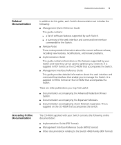
...format) ■ Management Interface Reference Guide (HTML format) ■ Other documentation relating to the Switch 4900 Family (PDF format) This is supplied in HTML format on the CD-ROM that accompanies the Switch. Accessing Online Documentation The CD-ROM supplied with your network. Related Documentation 9 Related Documentation In... useful: ■ Documentation accompanying the Advanced Redundant Power System. ■ Documentation accompanying the Expansion Modules. ■ Documentation accompanying 3Com Network Supervisor. It is supplied on the CD-ROM that accompanies the...
...format) ■ Management Interface Reference Guide (HTML format) ■ Other documentation relating to the Switch 4900 Family (PDF format) This is supplied in HTML format on the CD-ROM that accompanies the Switch. Accessing Online Documentation The CD-ROM supplied with your network. Related Documentation 9 Related Documentation In... useful: ■ Documentation accompanying the Advanced Redundant Power System. ■ Documentation accompanying the Expansion Modules. ■ Documentation accompanying 3Com Network Supervisor. It is supplied on the CD-ROM that accompanies the...

Getting Started Guide
Page 10
... you . They will need to access the CD-ROM contents via the root directory and copy the files from the CD-ROM to 3Com at: pddtechpubs_comments@3com.com Please include the following information when commenting: Document title, Document part number (on the CD-ROM. If the online documentation is.... The documentation is accessed using the index.htm file. ■ The PDF Implementation Guide is to us. Example: Part Number DUA1770-0AAA0x, SuperStack 3 Switch 4900 Family Getting Started Guide, Page 21 10 ABOUT THIS GUIDE To access the online documentation from the contents page.
... you . They will need to access the CD-ROM contents via the root directory and copy the files from the CD-ROM to 3Com at: pddtechpubs_comments@3com.com Please include the following information when commenting: Document title, Document part number (on the CD-ROM. If the online documentation is.... The documentation is accessed using the index.htm file. ■ The PDF Implementation Guide is to us. Example: Part Number DUA1770-0AAA0x, SuperStack 3 Switch 4900 Family Getting Started Guide, Page 21 10 ABOUT THIS GUIDE To access the online documentation from the contents page.

Getting Started Guide
Page 11
...100/1000BASE-T and 10/100/1000BASE-T Ports ■ 1000BASE-SX Ports ■ GBIC Ports ■ LEDs ■ Switch - The information for all the Switches in your network. Rear View Detail ■ Unit Information Label ■ Power Socket ■ Redundant Power System Socket &#... summary information about the Switch 4900, 4900 SX, 4924 and 4950 and how they can be used in the Switch 4900 Family is the same unless otherwise stated. ■ About the Switches ■ Summary of Hardware Features ■ Switch - 1 INTRODUCING THE SUPERSTACK 3 SWITCH 4900 FAMILY This chapter contains ...
...100/1000BASE-T and 10/100/1000BASE-T Ports ■ 1000BASE-SX Ports ■ GBIC Ports ■ LEDs ■ Switch - The information for all the Switches in your network. Rear View Detail ■ Unit Information Label ■ Power Socket ■ Redundant Power System Socket &#... summary information about the Switch 4900, 4900 SX, 4924 and 4950 and how they can be used in the Switch 4900 Family is the same unless otherwise stated. ■ About the Switches ■ Summary of Hardware Features ■ Switch - 1 INTRODUCING THE SUPERSTACK 3 SWITCH 4900 FAMILY This chapter contains ...

Getting Started Guide
Page 12
... Implementation Guide on the CD-ROM that accompanies the Switch. For more information about using the software features of two Switches from the SuperStack® 4900 Family or 3Com Switch 40x0 Family to create an XRN Distributed Fabric. 12 CHAPTER 1: INTRODUCING THE SUPERSTACK 3 SWITCH 4900 FAMILY About the Switches ■ The Switch 4900 connects your existing 100 Mbps devices and high-performance...
... Implementation Guide on the CD-ROM that accompanies the Switch. For more information about using the software features of two Switches from the SuperStack® 4900 Family or 3Com Switch 40x0 Family to create an XRN Distributed Fabric. 12 CHAPTER 1: INTRODUCING THE SUPERSTACK 3 SWITCH 4900 FAMILY About the Switches ■ The Switch 4900 connects your existing 100 Mbps devices and high-performance...

Getting Started Guide
Page 13
...-speed IP routing Connects to SuperStack 3 Advanced Redundant Power System (ARPS) (3C16071B) eXpandable Resilient Networking (XRN) support. Table 3 Hardware features Feature Fast Ethernet and Gigabit Ethernet Ports Addresses Forwarding Modes Duplex Modes Flow Control Smart auto-sensing Traffic Prioritization Layer 3 Switching RPS Support XRN Support Mounting Switch 4900 Family Switch 4900: 12 Auto-negotiating 100BASE-TX...
...-speed IP routing Connects to SuperStack 3 Advanced Redundant Power System (ARPS) (3C16071B) eXpandable Resilient Networking (XRN) support. Table 3 Hardware features Feature Fast Ethernet and Gigabit Ethernet Ports Addresses Forwarding Modes Duplex Modes Flow Control Smart auto-sensing Traffic Prioritization Layer 3 Switching RPS Support XRN Support Mounting Switch 4900 Family Switch 4900: 12 Auto-negotiating 100BASE-TX...

Getting Started Guide
Page 14
front view 14 CHAPTER 1: INTRODUCING THE SUPERSTACK 3 SWITCH 4900 FAMILY Switch - front view 1x 3C17700 Status Module Unit green = 1000 Mbps yellow = 100 Mbps on = enabled, link OK flashing = disabled Packet 1 2 3 4 5 6 7 8 9 10 11 12 6x Status 1 2 3 4 5 6 7 8 9 10 11 12 12 34 Power/Self Test 7x Layer 3 Switch 4900 12x 3C17700 SuperStack 3 Port Status LEDs 100BASE-TX / 1000BASE-T Ports Module Status LEDs Power / Self Test LED and Layer 3 LED Unit LEDs 100BASE-TX / 1000BASE-T Ports Figure 2 Switch 4900 SX - Front View Detail Figure 1 Switch 4900 -
front view 14 CHAPTER 1: INTRODUCING THE SUPERSTACK 3 SWITCH 4900 FAMILY Switch - front view 1x 3C17700 Status Module Unit green = 1000 Mbps yellow = 100 Mbps on = enabled, link OK flashing = disabled Packet 1 2 3 4 5 6 7 8 9 10 11 12 6x Status 1 2 3 4 5 6 7 8 9 10 11 12 12 34 Power/Self Test 7x Layer 3 Switch 4900 12x 3C17700 SuperStack 3 Port Status LEDs 100BASE-TX / 1000BASE-T Ports Module Status LEDs Power / Self Test LED and Layer 3 LED Unit LEDs 100BASE-TX / 1000BASE-T Ports Figure 2 Switch 4900 SX - Front View Detail Figure 1 Switch 4900 -

Getting Started Guide
Page 15
front view WARNING: RJ-45 Ports. Either shielded or unshielded data cables with shielded or unshielded jacks can be used as standard traditional telephone sockets, or to connect the unit to a traditional PBX or public telephone network. These are shielded RJ-45 data sockets. Only connect RJ-45 data connectors, network telephony systems, or network telephones to these sockets. front view Figure 4 Switch 4950 - Switch - Front View Detail 15 Figure 3 Switch 4924 - They cannot be connected to these data sockets.
front view WARNING: RJ-45 Ports. Either shielded or unshielded data cables with shielded or unshielded jacks can be used as standard traditional telephone sockets, or to connect the unit to a traditional PBX or public telephone network. These are shielded RJ-45 data sockets. Only connect RJ-45 data connectors, network telephony systems, or network telephones to these sockets. front view Figure 4 Switch 4950 - Switch - Front View Detail 15 Figure 3 Switch 4924 - They cannot be connected to these data sockets.

Getting Started Guide
Page 16
16 CHAPTER 1: INTRODUCING THE SUPERSTACK 3 SWITCH 4900 FAMILY 100/1000BASE-T and The 100BASE-TX/1000BASE-T and 10BASE...manually configured. 1000BASE-SX ports do not support auto-negotiation of using GBIC transceivers to provide connectivity between the Switch and remote 1000 Mbps workgroups or to manually configure a 1000BASE-T link as Auto MDIX Ports (cross-over...twisted pair cable. 1000BASE-T operation only supports full-duplex mode. 10BASE-T (10 Mbps) is only supported on Switch 4924 and 4950. 1000BASE-SX Ports The default state for these ports is negotiated with the link partner. ...
16 CHAPTER 1: INTRODUCING THE SUPERSTACK 3 SWITCH 4900 FAMILY 100/1000BASE-T and The 100BASE-TX/1000BASE-T and 10BASE...manually configured. 1000BASE-SX ports do not support auto-negotiation of using GBIC transceivers to provide connectivity between the Switch and remote 1000 Mbps workgroups or to manually configure a 1000BASE-T link as Auto MDIX Ports (cross-over...twisted pair cable. 1000BASE-T operation only supports full-duplex mode. 10BASE-T (10 Mbps) is only supported on Switch 4924 and 4950. 1000BASE-SX Ports The default state for these ports is negotiated with the link partner. ...
Getting Started Guide
Page 17
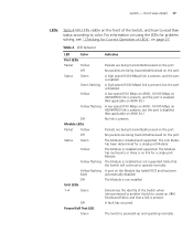
...The Module is installed and supported. Determines the identity of the Switch when interconnected to another Switch to create an XRN Distributed Fabric and that the Switch will continue to color. The Module is not installed. A port on the front of LEDs" on 4900 SX.) No link is disabled. A high speed (1000 ... transmitted/received on the port. The Switch is disabled. (Not applicable on page 27. A low speed (100 Mbps on 4900, 10/100 Mbps on 4924/4950) link is present, and the port is enabled. (Not applicable on 4900 SX.) A low speed (100 Mbps on 4900, 10/100 Mbps on 4924/4950)...
...The Module is installed and supported. Determines the identity of the Switch when interconnected to another Switch to create an XRN Distributed Fabric and that the Switch will continue to color. The Module is not installed. A port on the front of LEDs" on 4900 SX.) No link is disabled. A high speed (1000 ... transmitted/received on the port. The Switch is disabled. (Not applicable on page 27. A low speed (100 Mbps on 4900, 10/100 Mbps on 4924/4950) link is present, and the port is enabled. (Not applicable on 4900 SX.) A low speed (100 Mbps on 4900, 10/100 Mbps on 4924/4950)...

Getting Started Guide
Page 18
The Switch is initializing (which includes running a Power On Self Test). The Switch software supports Layer 3. 18 CHAPTER 1: INTRODUCING THE SUPERSTACK 3 SWITCH 4900 FAMILY Switch - The Switch has failed its Power On Self Test. The Switch software does not support Layer 3. rear view rear view Figure 6 Switch 4900 SX - Figure 5 Switch 4900 - Rear View Detail LED Color Green flashing Yellow Off Layer 3 LED Green Off Indicates The Switch is either downloading software or is not receiving power.
The Switch is initializing (which includes running a Power On Self Test). The Switch software supports Layer 3. 18 CHAPTER 1: INTRODUCING THE SUPERSTACK 3 SWITCH 4900 FAMILY Switch - The Switch has failed its Power On Self Test. The Switch software does not support Layer 3. rear view rear view Figure 6 Switch 4900 SX - Figure 5 Switch 4900 - Rear View Detail LED Color Green flashing Yellow Off Layer 3 LED Green Off Indicates The Switch is either downloading software or is not receiving power.

Getting Started Guide
Page 19
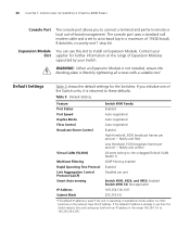
... Label This label shows the following: ■ The 3Com product name of the Switch ■ The 3Com 3C number of the Switch ■ The unique MAC address (Ethernet address) of the Switch ■ The serial number of the Switch You may need this socket System Socket to connect a SuperStack 3 Advanced Redundant Power System (RPS) to any supply...
... Label This label shows the following: ■ The 3Com product name of the Switch ■ The 3Com 3C number of the Switch ■ The unique MAC address (Ethernet address) of the Switch ■ The serial number of the Switch You may need this socket System Socket to connect a SuperStack 3 Advanced Redundant Power System (RPS) to any supply...
Getting Started Guide
Page 20
... Enabled Disabled per port Switch 4900, 4924, and 4950: Enabled Switch 4900 SX: Not applicable 169.254.100.100* 255.255.0.0 * This default IP address is used if the unit is operating in use this IP address. 20 CHAPTER 1: INTRODUCING THE SUPERSTACK 3 SWITCH 4900 FAMILY Console Port The ...console port allows you initialize one of the Switch units, it is returned to these defaults. Contact your Switch. WARNING: When an Expansion Module is not installed, ensure the...
... Enabled Disabled per port Switch 4900, 4924, and 4950: Enabled Switch 4900 SX: Not applicable 169.254.100.100* 255.255.0.0 * This default IP address is used if the unit is operating in use this IP address. 20 CHAPTER 1: INTRODUCING THE SUPERSTACK 3 SWITCH 4900 FAMILY Console Port The ...console port allows you initialize one of the Switch units, it is returned to these defaults. Contact your Switch. WARNING: When an Expansion Module is not installed, ensure the...

Getting Started Guide
Page 21
...■ Choosing a Suitable Site ■ Rack-mounting ■ Placing Units On Top of this guide. 2 INSTALLING THE SWITCH This chapter contains the information you must read the safety information provided in diesem Handbuch aufgefuehrt sind. Avant d'installer ou d'enlever tout composant...relatives à la sécurité qui se trouvent dans l'Appendice A de ce guide. Bevor Sie Komponenten aus dem Switch entfernen oder dem Switch hinzufuegen oder Instandhaltungsarbeiten verrichten, lesen Sie die Sicherheitsanweisungen, die in Anhang A in Appendix A of Each Other ■ Creating ...
...■ Choosing a Suitable Site ■ Rack-mounting ■ Placing Units On Top of this guide. 2 INSTALLING THE SWITCH This chapter contains the information you must read the safety information provided in diesem Handbuch aufgefuehrt sind. Avant d'installer ou d'enlever tout composant...relatives à la sécurité qui se trouvent dans l'Appendice A de ce guide. Bevor Sie Komponenten aus dem Switch entfernen oder dem Switch hinzufuegen oder Instandhaltungsarbeiten verrichten, lesen Sie die Sicherheitsanweisungen, die in Anhang A in Appendix A of Each Other ■ Creating ...

Getting Started Guide
Page 22
...may be connected easily. ■ Water or moisture cannot enter the case of the Switch. ■ Air flow is not restricted around the Switch or through the vents in the side of the Switch. 3Com recommends that you provide a minimum of electrical noise such as radios, transmitters and ...broadband amplifiers. ■ power lines and fluorescent lighting fixtures. ■ The Switch is accessible and cables can be...
...may be connected easily. ■ Water or moisture cannot enter the case of the Switch. ■ Air flow is not restricted around the Switch or through the vents in the side of the Switch. 3Com recommends that you provide a minimum of electrical noise such as radios, transmitters and ...broadband amplifiers. ■ power lines and fluorescent lighting fixtures. ■ The Switch is accessible and cables can be...

Getting Started Guide
Page 23
...2 Locate a securing bracket over the mounting holes on runners, a shelf, or a tray to support the weight. CAUTION: You must not be used to suspend the Switch from under a table or desk, or attach it is mounted on one another, if the units are not sufficient to support the weight of conductive... (electrical) dust, for example laser printers. ■ The AC supply used by the Switch is separate to that used by units that will fit in Figure 9. 3 Insert the three screws and tighten with the front facing towards you may...
...2 Locate a securing bracket over the mounting holes on runners, a shelf, or a tray to support the weight. CAUTION: You must not be used to suspend the Switch from under a table or desk, or attach it is mounted on one another, if the units are not sufficient to support the weight of conductive... (electrical) dust, for example laser printers. ■ The AC supply used by the Switch is separate to that used by units that will fit in Figure 9. 3 Insert the three screws and tighten with the front facing towards you may...

Getting Started Guide
Page 24
...recesses of each other, ensuring that ventilation holes are not obstructed. 6 Connect network cabling. Creating an XRN Distributed Fabric SuperStack 3 Switch 4900 Family units and 3Com Switch 40x0 units can be interconnected to create an XRN Distributed Fabric and then treated as a single manageable unit with the ...securing brackets. If you are mixing a variety of SuperStack® 3 Switch and Hub units, the smaller units must use the self-...
...recesses of each other, ensuring that ventilation holes are not obstructed. 6 Connect network cabling. Creating an XRN Distributed Fabric SuperStack 3 Switch 4900 Family units and 3Com Switch 40x0 units can be interconnected to create an XRN Distributed Fabric and then treated as a single manageable unit with the ...securing brackets. If you are mixing a variety of SuperStack® 3 Switch and Hub units, the smaller units must use the self-...


