
User Guide
Page 11
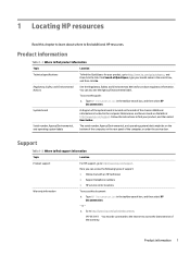
... rear panel of the chassis. Product information 1 To access this document: ▲ Type HP Documentation in the computer Maintenance and Service Guide on the Web at http://www.hp.com/support. Serial number, Agency/Environmental, and operating system labels The serial number, Agency/Environmental, and operating system labels might be connected to the Internet to access the latest version of support: ● Online chat with an HP technician ● Support telephone numbers ● HP service center locations...
... rear panel of the chassis. Product information 1 To access this document: ▲ Type HP Documentation in the computer Maintenance and Service Guide on the Web at http://www.hp.com/support. Serial number, Agency/Environmental, and operating system labels The serial number, Agency/Environmental, and operating system labels might be connected to the Internet to access the latest version of support: ● Online chat with an HP technician ● Support telephone numbers ● HP service center locations...
User Guide
Page 12
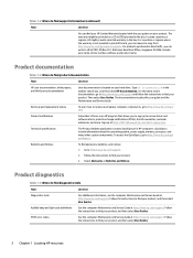
... find diagnostics tools Topic Location Diagnostics tools For additional information, see the computer Maintenance and Service Guide at http://www.hp.com/support. Go to find advisories, bulletins, and notices: 1. Select Advisories or Bulletins and Notices. The warranty might provide a printed warranty in the taskbar search box, and then select HP Documentation. QuickSpecs include information about the operating system, power supply, memory, processor, and...
... find diagnostics tools Topic Location Diagnostics tools For additional information, see the computer Maintenance and Service Guide at http://www.hp.com/support. Go to find advisories, bulletins, and notices: 1. Select Advisories or Bulletins and Notices. The warranty might provide a printed warranty in the taskbar search box, and then select HP Documentation. QuickSpecs include information about the operating system, power supply, memory, processor, and...

User Guide
Page 42
... create system restore points and recovery media. For details: ▲ Go to http://www.hp.com/support, search for restoring from backup, refreshing the computer, and resetting the computer to its original state (see Using Windows tools on page 32). Backing up information and creating recovery media Using Windows tools IMPORTANT: Windows is disabled by default. You can use the HP Cloud Recovery Download Tool to create HP Recovery media on a bootable USB flash drive. Enter the...
... create system restore points and recovery media. For details: ▲ Go to http://www.hp.com/support, search for restoring from backup, refreshing the computer, and resetting the computer to its original state (see Using Windows tools on page 32). Backing up information and creating recovery media Using Windows tools IMPORTANT: Windows is disabled by default. You can use the HP Cloud Recovery Download Tool to create HP Recovery media on a bootable USB flash drive. Enter the...

User Guide
Page 45
...select HP PC Hardware Diagnostics Windows. 2. The screen displays one of diagnostic test that you to run , and then follow the on-screen instructions. ● Instructions for calling support are provided. The tool runs within the Windows operating system to diagnose hardware failures. Type support in the taskbar. NOTE: To stop a diagnostic test, select Cancel. To access HP PC Hardware Diagnostics Windows from HP Support Assistant: a. Select HP PC Hardware Diagnostics Windows. - 5 Using HP PC Hardware Diagnostics Using HP PC Hardware Diagnostics Windows (select products only) HP PC...
...select HP PC Hardware Diagnostics Windows. 2. The screen displays one of diagnostic test that you to run , and then follow the on-screen instructions. ● Instructions for calling support are provided. The tool runs within the Windows operating system to diagnose hardware failures. Type support in the taskbar. NOTE: To stop a diagnostic test, select Cancel. To access HP PC Hardware Diagnostics Windows from HP Support Assistant: a. Select HP PC Hardware Diagnostics Windows. - 5 Using HP PC Hardware Diagnostics Using HP PC Hardware Diagnostics Windows (select products only) HP PC...

User Guide
Page 58
... changing 13 P product ID location 7 product information 1 R rear panel components 6 recovery 32 discs 33 HP Recovery partition 33 media 33 USB flash drive 33 recovery media creating using HP Cloud Recovery Download Tool 32 creating using Windows tools 32 Remote HP PC Hardware Diagnostics UEFI settings customizing 38 using 38 removing bezel blank 10 computer access panel 9 dust filter 12 expansion card 17 front bezel 11 hard drive 24 slim optical drive 22 resources, accessibility 46 restoring 32 S Section 508 accessibility standards 45 security cable 31 cable lock 30 serial number location...
... changing 13 P product ID location 7 product information 1 R rear panel components 6 recovery 32 discs 33 HP Recovery partition 33 media 33 USB flash drive 33 recovery media creating using HP Cloud Recovery Download Tool 32 creating using Windows tools 32 Remote HP PC Hardware Diagnostics UEFI settings customizing 38 using 38 removing bezel blank 10 computer access panel 9 dust filter 12 expansion card 17 front bezel 11 hard drive 24 slim optical drive 22 resources, accessibility 46 restoring 32 S Section 508 accessibility standards 45 security cable 31 cable lock 30 serial number location...

Maintenance and Service Guide
Page 5
... 65 Solving network problems ...66 Network driver does not detect network controller 66 Network status link light never blinks ...66 Diagnostics reports a failure ...66 Diagnostics passes, but the computer does not communicate with the network 67 Network controller stopped working when an expansion board was added to the computer 67 Network controller stops working without apparent cause 67 Cannot connect to network server when attempting remote system installation 67 System setup utility reports unprogrammed EEPROM 68 Solving memory problems ...69...
... 65 Solving network problems ...66 Network driver does not detect network controller 66 Network status link light never blinks ...66 Diagnostics reports a failure ...66 Diagnostics passes, but the computer does not communicate with the network 67 Network controller stopped working when an expansion board was added to the computer 67 Network controller stops working without apparent cause 67 Cannot connect to network server when attempting remote system installation 67 System setup utility reports unprogrammed EEPROM 68 Solving memory problems ...69...
Maintenance and Service Guide
Page 10
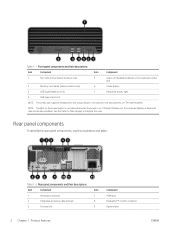
... jack 2 Memory card reader (select products only) 6 Power button 3 USB SuperSpeed ports (2) 7 Hard drive activity light 4 USB Type-A ports (2) NOTE: The combo jack supports headphones, line output devices, microphones, line input devices, or CTIA style headsets. Rear panel components To identify the rear panel components, use this illustration and table. See the {refer to MSG sample} to indicate a problem. If the light flashes red, the computer displays a diagnostic code to interpret the code. NOTE: The light on the power button is...
... jack 2 Memory card reader (select products only) 6 Power button 3 USB SuperSpeed ports (2) 7 Hard drive activity light 4 USB Type-A ports (2) NOTE: The combo jack supports headphones, line output devices, microphones, line input devices, or CTIA style headsets. Rear panel components To identify the rear panel components, use this illustration and table. See the {refer to MSG sample} to indicate a problem. If the light flashes red, the computer displays a diagnostic code to interpret the code. NOTE: The light on the power button is...

Maintenance and Service Guide
Page 58
... suspend mode, shut down , unplug the power cord, wait a few seconds, and then plug it in System Software Requirement Disks (SSRD). For example, if you encounter problems with the service technician. ● Remove any hardware that was recently added to see this list of general suggestions before running the restore process. Helpful hints If you are error codes that all cable connections for loose connections or incorrect connections. ● Wake...
... suspend mode, shut down , unplug the power cord, wait a few seconds, and then plug it in System Software Requirement Disks (SSRD). For example, if you encounter problems with the service technician. ● Remove any hardware that was recently added to see this list of general suggestions before running the restore process. Helpful hints If you are error codes that all cable connections for loose connections or incorrect connections. ● Wake...

Maintenance and Service Guide
Page 60
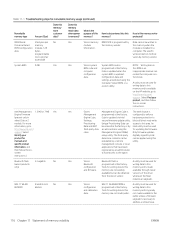
... properly connected and powered on installing a new battery, or contact an authorized dealer or reseller for RTC battery replacement. Check the front panel to troubleshoot the computer. 52 Chapter 5 Troubleshooting without diagnostics ENWW Poor performance Use this information to update the RTC date and time.) If the problem persists, replace the RTC battery. Check the Computer Setup settings to be used to troubleshoot the computer. See the Removal and Replacement section for instructions...
... properly connected and powered on installing a new battery, or contact an authorized dealer or reseller for RTC battery replacement. Check the front panel to troubleshoot the computer. 52 Chapter 5 Troubleshooting without diagnostics ENWW Poor performance Use this information to update the RTC date and time.) If the problem persists, replace the RTC battery. Check the Computer Setup settings to be used to troubleshoot the computer. See the Removal and Replacement section for instructions...

Maintenance and Service Guide
Page 72
... also use the Add Hardware Wizard, and follow the instructions for the board, and choose a basic configuration that pins in the cable or connector are disabled in the wrong location. Solution 1. In Windows, use Computer Setup to reconfigure or disable devices to integrate the device with other devices. Run the Computer Setup utility and ensure that appear on the computer are not bent down. Turn off the computer, turn on the external device, and then turn...
... also use the Add Hardware Wizard, and follow the instructions for the board, and choose a basic configuration that pins in the cable or connector are disabled in the wrong location. Solution 1. In Windows, use Computer Setup to reconfigure or disable devices to integrate the device with other devices. Run the Computer Setup utility and ensure that appear on the computer are not bent down. Turn off the computer, turn on the external device, and then turn...
Maintenance and Service Guide
Page 75
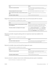
... do not match current configuration. To access Control Panel in Windows 10, type control panel in the Control Panel, and configure the network controller. Solution Be sure that the cable is installed. Network controller stopped working without apparent cause Use this information to the correct device. ENWW Solving network problems 67 Contact an authorized service provider. Contact an authorized service provider. Be sure that the cable is securely attached to the network connector and that the correct...
... do not match current configuration. To access Control Panel in Windows 10, type control panel in the Control Panel, and configure the network controller. Solution Be sure that the cable is installed. Network controller stopped working without apparent cause Use this information to the correct device. ENWW Solving network problems 67 Contact an authorized service provider. Contact an authorized service provider. Be sure that the cable is securely attached to the network connector and that the correct...

Maintenance and Service Guide
Page 93
.... Default is disabled. Reset Secure Boot keys to factory defaults Default is legitimate before booting to it, making Windows resistant to malicious modification from preboot to full operating system booting, preventing firmware attacks. Enable MS UEFI CA key Disabling this option to disable to support Device Guard. Ready BIOS for advanced users) (continued) Option Heading Secure Boot Configuration Configure Legacy Support and Secure Boot Lets you be enabled. Lets you turn off all legacy support on the computer, including booting to DOS, running legacy graphics cards, booting...
.... Default is disabled. Reset Secure Boot keys to factory defaults Default is legitimate before booting to it, making Windows resistant to malicious modification from preboot to full operating system booting, preventing firmware attacks. Enable MS UEFI CA key Disabling this option to disable to support Device Guard. Ready BIOS for advanced users) (continued) Option Heading Secure Boot Configuration Configure Legacy Support and Secure Boot Lets you be enabled. Lets you turn off all legacy support on the computer, including booting to DOS, running legacy graphics cards, booting...
Maintenance and Service Guide
Page 95
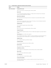
...is enabled. Internal Speakers (does not affect external speakers) Clear to disable the integrated microphone. Collaboration Buttons Clear to enable auto switching between a wired and wireless connection. Default is enabled. Allow No Panel configuration When enabled, POST blink and beep codes and error messages are not generated. This does not affect devices plugged into audio jacks. LAN/WLAN auto switching Select to disable the collaboration buttons. Increase Idle Fan Speed(%) Sets idle fan speed percentage. Video memory size Use this option to enable wake...
...is enabled. Internal Speakers (does not affect external speakers) Clear to disable the integrated microphone. Collaboration Buttons Clear to enable auto switching between a wired and wireless connection. Default is enabled. Allow No Panel configuration When enabled, POST blink and beep codes and error messages are not generated. This does not affect devices plugged into audio jacks. LAN/WLAN auto switching Select to disable the collaboration buttons. Increase Idle Fan Speed(%) Sets idle fan speed percentage. Video memory size Use this option to enable wake...
Maintenance and Service Guide
Page 99
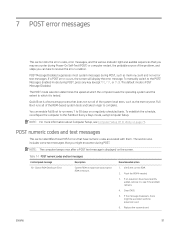
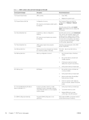
... a problem with them. Table 7-1 POST numeric codes and text messages Control panel message Description 101-Option ROM Checksum Error System ROM or expansion board option ROM checksum. Recommended action 1. Clear CMOS. 5. Flash the ROM if needed. 3. 7 POST error messages This section lists the error codes, error messages, and the various indicator light and audible sequences that have numeric codes associated with the expansion card. 6. The default mode is tested. Replace the system board. If a POST error occurs, the screen will display the error...
... a problem with them. Table 7-1 POST numeric codes and text messages Control panel message Description 101-Option ROM Checksum Error System ROM or expansion board option ROM checksum. Recommended action 1. Clear CMOS. 5. Flash the ROM if needed. 3. 7 POST error messages This section lists the error codes, error messages, and the various indicator light and audible sequences that have numeric codes associated with the expansion card. 6. The default mode is tested. Replace the system board. If a POST error occurs, the screen will display the error...
Maintenance and Service Guide
Page 100
... Devices. Clear CMOS. 2. Replace the system board. 162-System Options Not Set Configuration incorrect. Reset the date and time under Control Panel (You can also use Computer Setup). If the problem persists, replace the RTC battery. 163-Time & Date Not Set Invalid time or date in the error message is missing critical SPD information, or is not optimized. RTC (real-time clock) battery may need to save the memory boot (memory added or removed). changes. 164...
... Devices. Clear CMOS. 2. Replace the system board. 162-System Options Not Set Configuration incorrect. Reset the date and time under Control Panel (You can also use Computer Setup). If the problem persists, replace the RTC battery. 163-Time & Date Not Set Invalid time or date in the error message is missing critical SPD information, or is not optimized. RTC (real-time clock) battery may need to save the memory boot (memory added or removed). changes. 164...

Maintenance and Service Guide
Page 101
... hard drive is not connected or might have malfunctioned. 1. Reconnect keyboard with computer turned off. 2. Replace the keyboard. 4. If additional memory was recently added, remove it to see if the problem remains. 2. Be sure that none of the keys are depressed. 4. Reseat fan. 2. Reseat fan cable. 3. Reseat fan cable. 3. Reconnect keyboard with computer turned off . 2. Replace the system board. 501-Display Adapter Failure Graphics display controller. 1. Reflash the system ROM with computer turned off . 2. Reconnect the keyboard with the latest BIOS...
... hard drive is not connected or might have malfunctioned. 1. Reconnect keyboard with computer turned off. 2. Replace the keyboard. 4. If additional memory was recently added, remove it to see if the problem remains. 2. Be sure that none of the keys are depressed. 4. Reseat fan. 2. Reseat fan cable. 3. Reseat fan cable. 3. Reconnect keyboard with computer turned off . 2. Replace the system board. 501-Display Adapter Failure Graphics display controller. 1. Reflash the system ROM with computer turned off . 2. Reconnect the keyboard with the latest BIOS...

Maintenance and Service Guide
Page 122
... Reset BIOS Security to reject. k. Press or tap f1 to accept or f2 to factory default. l. Turn on -screen instructions to the Utilities menu. e. g. Select Hard Drive Utilities, select DriveLock, and then clear the check box for at the bottom of memory volatility ENWW Click Yes at the prompt. During the reboot, press esc while the "Press the ESC key for Startup Menu" message is set , select the Security menu...
... Reset BIOS Security to reject. k. Press or tap f1 to accept or f2 to factory default. l. Turn on -screen instructions to the Utilities menu. e. g. Select Hard Drive Utilities, select DriveLock, and then clear the check box for at the bottom of memory volatility ENWW Click Yes at the prompt. During the reboot, press esc while the "Press the ESC key for Startup Menu" message is set , select the Security menu...
Maintenance and Service Guide
Page 124
... manner can be used for EEPROM kilobits configuration programmed at the factory. Management Engine Code is available on -screen instructions. memory are entered using the Management Engine (MEBx) setup utility. writing data to this and calibration Tools for writing data to this memory and is necessary to this memory retain data when power is updated via Intel secure firmware update utility. module is typically data. screen instructions.) Stores Management Engine Code, Settings, Provisioning Data and...
... manner can be used for EEPROM kilobits configuration programmed at the factory. Management Engine Code is available on -screen instructions. memory are entered using the Management Engine (MEBx) setup utility. writing data to this and calibration Tools for writing data to this memory and is necessary to this memory retain data when power is updated via Intel secure firmware update utility. module is typically data. screen instructions.) Stores Management Engine Code, Settings, Provisioning Data and...
Maintenance and Service Guide
Page 133
... battery replacement 43 beep codes 95 blinking lights 95 boot order, changing 112 booting options Full Boot 91 Quick Boot 91 C cable management 11, 19, 20 cable pinouts, SATA data 11, 19 cables 9 changing a Power-On password 99 changing a Setup password 99 cleaning computer 11, 16 mouse 11, 16, 17 safety precautions 11, 16 CMOS clearing and resetting 99 components front panel 1 rear panel 2 computer cleaning 11, 16 Computer Setup access problem 51 Advanced menu 83 Main menu 76 Security menu 79 Computer Setup Utility 75 country power cord set...
... battery replacement 43 beep codes 95 blinking lights 95 boot order, changing 112 booting options Full Boot 91 Quick Boot 91 C cable management 11, 19, 20 cable pinouts, SATA data 11, 19 cables 9 changing a Power-On password 99 changing a Setup password 99 cleaning computer 11, 16 mouse 11, 16, 17 safety precautions 11, 16 CMOS clearing and resetting 99 components front panel 1 rear panel 2 computer cleaning 11, 16 Computer Setup access problem 51 Advanced menu 83 Main menu 76 Security menu 79 Computer Setup Utility 75 country power cord set...
Maintenance and Service Guide
Page 134
... 5 operating voltage range 123 removal and replacement 42 Power-On password 99, 100 printer problems 61 problems audio 59 Computer Setup 51 F10 Setup 51 flash drive 71 general 51 hard drive 57 hardware installation 64 internet access 72 keyboard 63 memory 69 mouse 63 network 66 power 55 printer 61 software 73 processor illustrated 5 removal and replacement 40 product features 1 product ID locations 3 R rear panel components 2 recovery 109, 111 discs 111 media 111 USB flash drive 111 recovery media 110 creating using HP Cloud Recovery Download Tool 110 creating using Windows tools 110 Remote HP...
... 5 operating voltage range 123 removal and replacement 42 Power-On password 99, 100 printer problems 61 problems audio 59 Computer Setup 51 F10 Setup 51 flash drive 71 general 51 hard drive 57 hardware installation 64 internet access 72 keyboard 63 memory 69 mouse 63 network 66 power 55 printer 61 software 73 processor illustrated 5 removal and replacement 40 product features 1 product ID locations 3 R rear panel components 2 recovery 109, 111 discs 111 media 111 USB flash drive 111 recovery media 110 creating using HP Cloud Recovery Download Tool 110 creating using Windows tools 110 Remote HP...


