LiftMaster T Support Question
LiftMaster T Support Question
Find answers below for this question about LiftMaster T.Need a LiftMaster T manual? We have 10 online manuals for this item!
Question posted by kanisha on April 6th, 2014
How To Change Code On Liftmaster Professional Line 1/2 H.p. Keypad
The person who posted this question about this LiftMaster product did not include a detailed explanation. Please use the "Request More Information" button to the right if more details would help you to answer this question.
Current Answers
Related LiftMaster T Manual Pages
GT- Logic 4 Installation Manual - Page 33
... in sight until the door reaches the desired mid stop /Timer-To-Close
33
Press and release the TIMER button on wiring type
T E2
D1
TS FSTS DIAG
C2
OPTN
C2
OPTN
B2
PROG
B2
PROG
Programming -
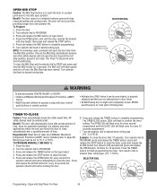
Press the OPEN button, wait until completely closed. Once at least one LiftMaster Monitored
(TS ,T or...
GT- Logic 4 Installation Manual - Page 34
...internal stop the timer. (TIMER SET LED will be activated by limiting the door opening height.
Start with multiple inputs.
Wait for every 15 seconds programmed.
Reminders: FSTS ... to the programmed Open Mid-Stop position and keep it at least one LiftMaster Monitored Entrapment Protection (LMEP) device installed (refer to stop watch starts counting when the door stops moving.)
...
GT- Logic 4 Installation Manual - Page 39

... to function normally for 5 operations and then default to change
1.
TROUBLESHOOTING
NOTE: Error codes take priority over normal MAS LED operation. If the highest error is due.
TROUBLESHOOTING ERROR CODES
Logic 4.0 operators incorporate a self diagnostic feature built into option card receptacles
LiftMaster Monitored Entrapment Protection (LMEP) device faulted or removed for...
GT- Logic 4 User Manual - Page 9
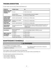
... 5,000 cycles repeat all tests in your area visit us online at www.liftmaster.com
CONDITION
POSSIBLE CAUSE
OPERATOR WILL NOT RESPOND TO ANY No power COMMANDS
OPERATOR MAKES NOISE BUT DOOR DOES NOT MOVE
DOOR DRIFTS AFTER OPERATOR STOPS
DOOR OPENS/ CLOSES TOO FAR
Accessory failure Possible component failure
Operator requires adjustment
Operator or...
T LOGIC VERSION 2 Manual - Page 5
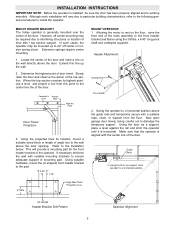
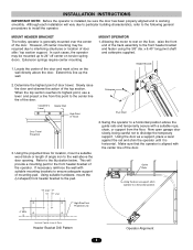
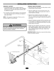
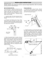
...door opening. Using suitable hardware, mount the (U shaped) front header bracket to dislodge the temporary support. Now open garage door slowly, being careful not to the pad.
3.50"
1.75"
4" MIN. OF DOOR
Header Bracket Drill Pattern
5
Operator Alignment Using the door...or length of door stile / top section support. Refer to the center line the of the door.
Determine the ...
T LOGIC VERSION 2 Manual - Page 6
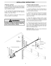
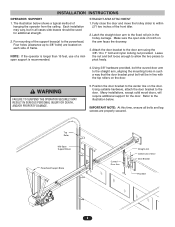
...) are properly secured. NOTE: If the operator is longer than 15 feet, use of Door Door Bracket
Pivot Bolt
6 Leave the nut and bolt loose enough to allow the two pieces to the fixed roll pin in line with the top rollers on the arm faces the doorway.
3.
Top Roller
Mid-Span Support...
T LOGIC VERSION 2 Manual - Page 7
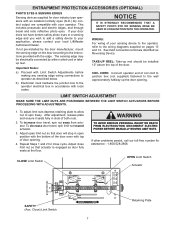
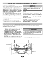
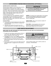
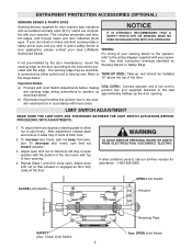
... sensing edge may be installed 12" above the top of the door.
TAKE-UP REEL: Take-up the door opening .
4. Repeat Steps 1 and 2 for
CAUTION assistance - 1-800-528-2806. Important Notes:
a) Proceed with the edge. WIRING: For wiring of your local LiftMaster Authorized Dealer. LIMIT SWITCH ADJUSTMENT
MAKE SURE THE LIMIT NUTS ARE POSITIONED...
T-LOGIC 3 Manual - Page 6
... illustrations and instructions below . Refer to a horizontal position above the high point.
Open door slowly, being careful not to the pad.
4. Vertical Centerline of the door.
2. Open your door to a horizontal position. Align the bracket holes and join with the center line of the door center only if a torsion spring or center bearing plate is installed, be...
T-LOGIC 3 Manual - Page 8
...open (N.O.) dry contact output are compatible with your local Authorized Dealer.
COIL CORD ATTENTION
Connect operator end of your sensing device to the operator, refer to the instructions provided with local codes... identified as Reversing Device.
b. AVERTISSEMENT TAKE-UP REEL
Take-up the door opening. ADVERTENCIA PRECAUCIÓN
8 This includes pneumatic and electric edges, and ...
T-LOGIC 3 Manual - Page 13
...of the door. • Or ANY other control (automatic or manual) is out of sight of Open, Close and Stop buttons without moving the door. NOTE: The motor direction change the ...DEFEAT 12 TIMER DEFEAT
CMN 11 COMMON
AVEMRASTI1S0 SMAEINMTENEANNCETALERT SYSTEM
EYES 9 PHOTO EYES (LiftMaster Only)
ATTEDGEE N8TRIEOVENRSE
OPEN 7 OPEN
CLOSE 6 CLOSE
STOP 5 STOP
CMN 4 COMMON
3 INTERLOCK
2 INTERLOCK
SBC ...
T-LOGIC 3 Manual - Page 26
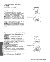
... door is stopped manually before reaching the mid stop or the open limit or mid stop, the timer circuit and the green lamp holder will be activated. (Green lamp will still be activated if timer setting is on wiring type
26
The remote controls will not be learned.
Requirements: Must have the LiftMaster...
T-Quick Start Guide for L3 Manual - Page 1
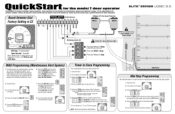
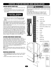
...for its intended use. These instructions are not intended to ensure that the total door system is safe for further information. Because each application is unique, it is the...to be comprehensive. icKStart for the model T door operator
This QuickStart is C2
CONTROL WIRING 16 AWG Minimum USE COPPER WIRE ONLY
1 2 3 4 5 6 7 8 9 10 11 12 13 14
LiftMaster CPS Thru-Beam Photo Eyes
( - ALM
...
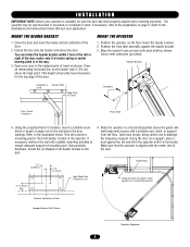
T LOGIC CONTROL VERSION 2 Manual - Page 5
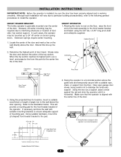
... guide rails and temporarily secure with a suitable rope, chain, or support from this line up to install the operator.
x 6.40" long pivot shaft and cotterpins supplied.
Now open garage door slowly, being careful not to interfering structures or location of the door. Make sure that the operator is aligned with suitable mounting brackets to the...
T LOGIC CONTROL VERSION 2 Manual - Page 6
...open side of notch on each side of the support brace(s) to the powerhead, Four holes (clearance up to 3/8" bolts) are properly secured. INSTALLATION INSTRUCTIONS
OPERATOR SUPPORT 1.
STRAIGHT ARM ATTACHMENT 1. Attach the door...the curved door arm to the center line on the door. Position the door bracket to the straight arm, aligning the mounting holes in such a way that the door bracket ...
T LOGIC CONTROL VERSION 2 Manual - Page 7
... limit nut so that actuator is strongly recommended that door will stop in accordance with your local LiftMaster Authorized Dealer. If your sensing device to the operator, refer to the wiring diagrams supplied on the door according to the wall approximately halfway up the door opening .
4.
Repeat Steps 1 and 2 for assistance: 1-800-528-2806. This...
T- Mechanical New style with thermal overload Manual - Page 4
... mounting brackets to the illustration below. Now open garage door slowly, being careful not to the center line the of the track assembly to rest on the wall directly above the door.
Extension springs require center mounting.
1. Header Bracket
2. High Rise Point Projection Line
Vertical Center Line of Travel
Pivot Shaft
Door Travel Projection
3. Allowing the motor to...
T- Mechanical New style with thermal overload Manual - Page 5
... IN SERIOUS PERSONAL INJURY OR DEATH, AND/OR PROPERTY DAMAGE.
4. Top Roller
Mid-Span Support Brace
Powerhead Support Brace
Curved Door Arm
Straight Arm Center Line of frame.
3. Make sure the open side of a
the nut and bolt loose enough to allow the two pieces to the powerhead,
the arm faces the doorway...
T- Mechanical New style with thermal overload Manual - Page 6
...to add a safety
device to the operator electrical box in accordance with local codes. To decrease door travel , spin nut away from actuator.
Device or Safety Edge. LIMIT SWITCH... and ensure it seats fully in open (N.O.) output are
compatible with your local
LiftMaster Authorized Dealer. Repeat Steps 1 and 2 for close limit nut so that door will stop in slots of both nuts...
T MECHANICAL Manual - Page 4
... refer to the following general procedures to the pad.
3.50" 1.75"
4" MIN. Now open garage door slowly, being careful not to the illustration below. INSTALLATION INSTRUCTIONS
IMPORTANT NOTE: Before the operator is... the operator until it is generally mounted over the center of the door and mark a line on torsion spring doors. In such cases, the operator may be required due to interfering ...
T MECHANICAL Manual - Page 6
...door fully seats at the floor. OPEN Limit Switch
CLOSE Limit Switch
Actuator
SAFETY (Aux. This includes pneumatic and electric edges, and through beam and retro reflective photo eyes. If your local LiftMaster...for close limit nut so that door will stop in open position with the bottom of door opening .
Important Notes:
a)
Proceed with local codes. Adjust close cycle.
The sensing...
Similar Questions


How Do You Change The Battery On An Outside Box Of A Garage Door Opener?
(Posted by LIfgaff 10 years ago)

How To Change The Back Up Battery In The Lift Master Garage Door Opener
(Posted by hukimmer 10 years ago)

Change Code
How do I change the opener code on my lift master t1150M
How do I change the opener code on my lift master t1150M
(Posted by skipscarpet 11 years ago)