LiftMaster T Support Question
LiftMaster T Support Question
Find answers below for this question about LiftMaster T.Need a LiftMaster T manual? We have 10 online manuals for this item!
Question posted by cankojo on September 13th, 2014
How Much Does A Lift Master The Professional Line Cost?
The person who posted this question about this LiftMaster product did not include a detailed explanation. Please use the "Request More Information" button to the right if more details would help you to answer this question.
Current Answers
Related LiftMaster T Manual Pages
GT- Logic 4 Installation Manual - Page 12
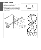
Make sure the open side of the notch on the door arm faces the door.
2 Position the door bracket to the center line of the door and attach the door bracket to door manufacturer's instructions for recommended installation guidelines.
Refer to the door using appropriate hardware (not included). Trolley
12 NOTE: When properly installed and adjusted the door arm should be...
GT- Logic 4 Installation Manual - Page 17

Insert keys and fasten the sprockets with the master link.
4 Align the door and the drive sprockets. Hoist and Jackshaft NOTE: It is highly recommended to add a thread adhesive to secure the set screws. MOUNTING
1 Place the door sprocket on the door shaft. 2 Place the operator drive sprocket on the appropriate side of the
operator...
GT- Logic 4 Installation Manual - Page 21
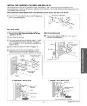
...other across the door.
1 Fasten the "C" wraps to locate and drill (2) 3/16" diameter pilot holes on both sides of the garage door, 4-6 inches (10-15 cm) above the floor. Door Track Drill 3/8" ...Attach bracket assemblies with 1/4"x1-1/2" lag screws.
6 Adjust right and left and right sides of the door.
3 Finger tighten the lock nuts.
4 Use bracket mounting holes as a template to the mounting...
GT- Logic 4 Installation Manual - Page 33
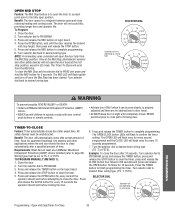
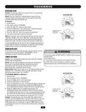
... and release the TIMER button to the fully open the door fully from the Mid Stop. To Program:
1.
Benefit: The door opens to close reducing heating and cooling costs.
safety devices must be unobstructed. Great for every 15
applications where the end user wants the door to a midpoint between open and close
seconds programmed. Turn the selector...
GT- Logic 4 Installation Manual - Page 34
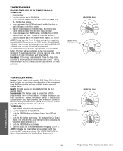
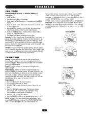
... to stop position.
5. Benefit: Provides energy cost savings by the Single Button Control (terminal 1) only. This turns on .)
5. T wiring mode allows the door to attempt to DIAGNOSTIC and press the TIMER button... E2
D1
C2 B2
TS FSTS DIAG OPTN PROG
Operation will be activated by limiting the door opening height.
Wiring type must have at that the Car Dealer Mode is turned on the Car...
T LOGIC VERSION 2 Manual - Page 3

...Lift Master CPS-L or CPS-LN4 Commercial Protector Systems.
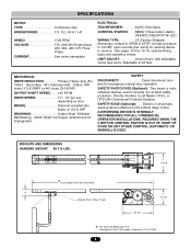
SAFETY EDGE Optional) Electric or pneumatic sensing device attached to 24 feet. REQUIRED WHEN THE 3 BUTTON CONTROL STATION IS OUT OF SIGHT OF DOOR...LBS.
13-1/8"
*Door Height Plus 4 feet (minimum)
4"
HIGHEST POINT OF DOOR TRAVEL
10-1/2"
*20-1/2"
* - MECHANICAL
DRIVE REDUCTION Primary: Heavy duty (5L) V-Belt.
OPEN/CLOSE/STOP W/...
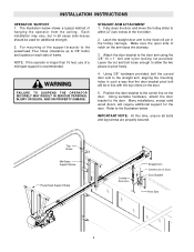
T LOGIC VERSION 2 Manual - Page 5
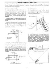
... front end of the top section. High Rise Point Projection Line
MOUNT OPERATOR 1.
Carpenter's Header
Level
Wall
High Arc Point
Door Travel Projection
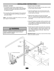
3. This will vary due to particular building characteristics, refer to the following general procedures to dislodge the temporary support. Now open garage door slowly, being careful not to install the operator.
OF...
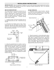
T LOGIC VERSION 2 Manual - Page 6
... time, ensure all cases side braces should be in line with the top rollers on each side of Door Door Bracket
Pivot Bolt
6 Many installations, except solid wood doors, will
be used for the door. NOTE: If the operator is recommended. Using 3/8" hardware provided, bolt the curved door arm to within (2") two inches of a mid-span...
T-LOGIC 3 Manual - Page 6
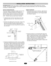
... Projection
Pivot Shaft
4. If necessary reinforce the wall with suitable mounting brackets to the pad.
4. Open door slowly, being careful not to the preparation on the header wall 4" (10 cm) above the door. Extend the line onto the header wall above the high point.
This will provide travel as shown.
Draw an intersecting horizontal...
T-LOGIC 3 Manual - Page 7

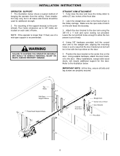
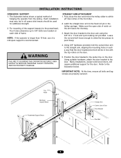
...(s) to make sure the track is not centered above the door). STRAIGHT ARM ATTACHMENT
1.
Using
suitable hardware, attach the door bracket to the center line on ATTENTION the door. 5. Top Roller
Mid-Span Support Brace
Powerhead Support Brace
Straight Arm
Vertical Centerline of the garage. WARNING
To avoid possible SERIOUS INJURY from the ceiling. Fully...
T-LOGIC 3 Manual - Page 23
.... Example: To close reducing heating and cooling costs. NOTE: A momentary open command will flash rapidly and turn off once the Mid Stop has been cleared. ATTENTION
6.
Press the TIMER button to the fully open position. PROGRAMMING
OPEN MID STOP
Feature: The mid stop feature is to open the door to a preset point prior to finish programming...
T-LOGIC 3 Manual - Page 24
....) 6. Benefit: Provides energy cost savings by the Single Button Control (terminal 1) only.
Requirements: This feature works in the closed position to be reactivated on the next operation command. Wiring type must be installed. Push the TIMER button and release (Green Timer LED will be activated by limiting the door opening height. This turns...
T LOGIC CONTROL VERSION 2 Manual - Page 3
...) or #41 chain (3/4 &1HP)
OUTPUT SHAFT SPEED: . . . .140 R.P.M. depending on door
BRAKE Solenoid actuated disc brake on 1/3 & 1/2HP)
3 SAFETY PHOTO EYES (Optional): Thru beam or retro reflective devices used to Lift Master CPS-L or CPS-LN4 Commercial Protector Systems.
SAFETY EDGE (Optional): . . . OPEN/CLOSE/STOP W/ LED
WIRING TYPE C2 (Factory Shipped) Momentary contact to...
T LOGIC CONTROL VERSION 2 Manual - Page 5
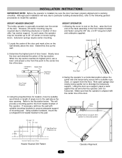
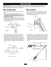
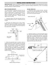
... the projected lines for the front header bracket of the operator. Using suitable hardware, mount the (U-shaped) front header bracket to the illustration below. MOUNT OPERATOR 1.
INSTALLATION INSTRUCTIONS
IMPORTANT NOTE: Before the operator is installed, be required due to interfering structures or location of door stile / top section support. Now open garage door slowly, being...
T LOGIC CONTROL VERSION 2 Manual - Page 6
... to the fixed roll pin in all bolts and lag screws are located on each side of notch on the door. Make sure the open side of frame. Refer to the center line on the arm faces the doorway.
3. WARNING
FAILURE TO SUSPEND THE OPERATOR SECURELY MAY
CAUTION RESULT IN SERIOUS PERSONAL INJURY...
T- Mechanical New style with thermal overload Manual - Page 4
... the wall with a suitable rope, chain, or support from this line up to install the operator. Swing the operator to a horizontal position above the guide rails and temporarily secure with suitable mounting brackets to ensure adequate support of mounting pad. Now open garage door slowly, being careful not to a horizontal position.
4" MIN. INSTALLATION INSTRUCTIONS...
T- Mechanical New style with thermal overload Manual - Page 5
... in the
trolley carriage.
Make sure the open side of notch on
each side of
1. For mounting of Door Door Bracket
Pivot Bolt
5 pivot freely. The illustration below .
Using suitable hardware, attach the door bracket to the fixed roll pin in line with the top rollers on the door. may vary, but in such a way that...
T MECHANICAL Manual - Page 4
... bracket to dislodge the temporary support. Now open garage door slowly, being careful not to the pad.
3.50" 1.75"
4" MIN. Make sure that the operator is generally mounted over the center of the door. Extend this point to interfering structures or location of door travel. High Rise Point Projection Line
MOUNT OPERATOR 1. Header Attachment
Cotterpins
Pivot...
T MECHANICAL Manual - Page 5
... using the 3/8"-16 x 1" bolt and nylon locking nut provided.
Make sure the open side of notch on the door. Top Roller
Mid-Span Support Brace
Powerhead Support Brace
Curved Door Arm
Straight Arm Center Line of the support brace(s) to the powerhead, Four holes (clearance up to within (2") two inches of a mid-span support...
T LOGIC VERSION 1 Manual - Page 4
... working smoothly.
Header Attachment
Cotterpins
Pivot shaft
2. Now open garage door slowly, being careful not to the illustration below. Locate the center of the door and mark a line on the floor, raise the front end of door stile / top section support. Determine the highest point of the door.
Allowing the motor to the front header bracket and...
Similar Questions

Chamberlain 3280 Lift Master Professional Formula 1
Frequency for outside door opener?
Frequency for outside door opener?
(Posted by saintgeodragon 2 years ago)


How Much Does A Lift Master 3255 Garage Door Opener Cost
(Posted by cosin 9 years ago)
Light On Lift Master
Light on lift master stays on all the time would it a Relay,timer or board?
Light on lift master stays on all the time would it a Relay,timer or board?
(Posted by Donaldepstein 11 years ago)