LiftMaster SL585 Support Question
LiftMaster SL585 Support Question
Find answers below for this question about LiftMaster SL585.Need a LiftMaster SL585 manual? We have 1 online manual for this item!
Question posted by Dkprlp on January 21st, 2013
Door Bell Button
Can I use a std door bell button as a secondary control
Current Answers
Related LiftMaster SL585 Manual Pages
SL595 Manual - Page 1

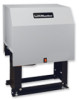
GLCONTROLLER BOARD
MODEL SL585
HEAVY DUTY SLIDE GATE OPERATOR
2 YEAR WARRANTY
Serial located on electrical box cover) Installation Date
MODEL SL595
HEAVY DUTY, HARSH ENVIRONMENT SLIDE GATE OPERATOR
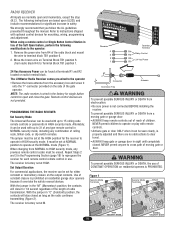
MODELS SL585 AND SL595 ARE FOR VEHICULAR PASSAGE GATES ONLY AND ARE NOT INTENDED FOR
PEDESTRIAN PASSAGE GATE USE
SL595 Manual - Page 2

... AND MAINTENANCE
for Secondary Entrapment Protection . ... Brake 24
Friction Clutch 24
HARDWARE KIT SL585/SL595 (K77-34846)
Control Board Programming and Features 24-25
AVER... the possibility of damage to your commercial door and gate operator unless you see this...(SL585 only 9 Post Mounting (SL585 & SL595 10
CAUTION Install Gate Bracket and Drive Chain 11
Available Conduit Access for Open...
SL595 Manual - Page 3

OPERATOR DIMENSIONS AND HORSEPOWER CHART
MODEL SL585
• 1/2 HP Motor Maximum Gate Speed - 11"/sec. (27.9 cm/sec.) Maximum Gate Weight - 1000 lbs. (453.6 kg) Maximum Cantilever Gate Width - 25 ft....Width - 60 ft. (18.3 m)
24" (61 cm)
Gate Side
16.5" (41.9 cm)
13.5" (34.3 cm)
22.5" (57.2 cm)
30" (76.2 cm)
Allow For Door Opening
12" Min. (30.5 cm)
3" (7.6 cm) Dia. Pipe (Not Provided)
3
SL595 Manual - Page 4
... both the open and close directions of the four UL325 classes. Both primary and secondary entrapment protection methods must have one primary means of entrapment protection and one independent secondary means of motorized gate systems.
Moving Gate Can Cause Injury or Death
KEEP CLEAR! Constant pressure control.
4 Type B2: Connections provided for use in which...
SL595 Manual - Page 9
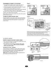
...Side
Power and Control Wiring Must Be Run In Separate Conduit
1/2" Concrete Anchors
(4 Required)
2" to 4" (5.1 to the concrete pad using four
1/2" concrete...SL585 ONLY)
Figure 1
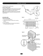
RETRO-FIT INSTALLATION
The operator is shipped from the factory with the lower mounting angles configured out (Figure 1).
NEW INSTALLATION Concrete Pad Preparation 1. If you are replacing an SL580 and wish to use...
SL595 Manual - Page 10
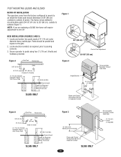
...By Local Codes or Below Frost Line
SL585 ONLY
Figure 2
Drive and Idler Sprocket Toward Gate Side
Angle Bracket
3" (7.6 cm) U-bolt (4 required)
Power and Control Wiring Must Be Run In Separate Conduit
...concrete.
3. Secure operator to posts using four 3" (7.6 cm) U-bolts and hardware provided.
26" (66 cm)
Post to outside (Figure 1). POST MOUNTING (SL585 AND SL595)
RETRO-FIT INSTALLATION
The...
SL595 Manual - Page 11

Remove the operator cover or open access door.
2" (5.1 cm) U-bolts
With Lock Washers
AVERTISSEMENT 3. and Nuts
4. If positioned properly, this brace can also be...in line with each other.
Ensure that are in place (refer to remove chain slack.
This may also be used as shown. INSTALL GATE BRACWKEAT ARNDNDIRNIVGE CHAIN
CAUTION
To prevent damage to the operator or gate, DO NOT drive ...
SL595 Manual - Page 12
..., power connections must be required for engagement.)
MODEL SL595 DISENGAGEMENT:
RE-ENGAGEMENT:
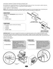
Open the hinged door and pull the disconnect lever and lock it in place. Rotate handle back to... factory as 3/4" and 1" knock outs for correct wire gauges.
MANUAL DISCONNECT
MODEL SL585 DISENGAGEMENT:
RE-ENGAGEMENT:
Rotate disconnect handle 90˚ to wiring specifications on pages ...
SL595 Manual - Page 13
... open or has difficulty opening .
Adjust with adjustments.
1.
Locate the 3-button control that is properly mounted and
secured.
1. Push the close button and observe the operator's behavior. Remove control panel... may become necessary to shipping vibration or rough handling. AVERT These operators use an internal entrapment protector system. This system consists of SEVERE INJURY or ...
SL595 Manual - Page 14

... Section on page 15. This input will pause an opening gate to the close limit.
Transformer Electrical Box
Obstruction While Closing (Edge/Photo eye with N.O. MODEL SL595
Pin
MODEL SL585
Pin
UL325 ENTRAPMENT PROTECTION
PRIMARY ENTRAPMENT PROTECTION ADJUSTMENTS Force Control Set the force control pot such that the unit will stop and alarm. Once...
SL595 Manual - Page 15
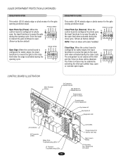
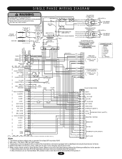
... Drive Troubleshooting LEDs
J1 Terminal Troubleshooting LEDs
15
Limit LEDs
Programming Port (factory use only)
Motor Learn Button
J3 Connector Aux.
CONTROL BOARD ILLUSTRATION
Main Terminal Wiring
J4 Connector Master/Second
Dip Switch #4 Master/Second
Potentiometer Timer-to
ON
the open S2
limit when activated during the ON
close cycle. PHOTO CLOSE
CLED
OPED...
SL595 Manual - Page 17
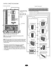
...where the user cannot come into contact with accessory kit for assistance. Close Override Control Input (N.O.)
OPEN CLOSE STOP
Stop/Reset Control Input (N.C.)
OPEN CLOSE STOP
Shadow Loop Input (N.O.)
Radio (Single Button) Input (N.O.)
FREQ FREQ
Soft Open Input (N.O.)
123 56
789 0#
Hard Open Override Control Input (N.O.)
OPEN CLOSE STOP
Interrupt (Safety) Loop Input (N.O.)
Obstruction While...
SL595 Manual - Page 18
.... When using a remote control or Single Button Control Station in the "M" (Momentary) position, the contacts will stay closed .
NORMAL security mode, including any type remote control in
NEVER... box and screw it
onto the "F"-connector provided on residential garage door openers because it can be used with remote controls.
WARNING
The receiver is factory set at M. With the ...
SL595 Manual - Page 19
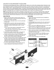
... that you wish to the following two conditions: (1) this device may be used to operator (Figure 3).
2.
Control Conduit
Control Conduit
1 234 567
12 3
Stop/Reset Button
Stop/Reset Button
1 2 3 4 5 6 7 8 9 10 11 12 13 14
123 56
789 0#
Soft Open
19 Press and release the "learn " button on the operator.
NOTE: Will not override a double entrapment (signalled by...
SL595 Manual - Page 22
...
6. Once the slide or swing gate reaches the open position the barrier will open cycle.
3. Attach a wire from terminal 5 of the SL585/595 accessory wiring terminal block to initiate the SAM ..., the swing or slide gate.
2. Test for SAMS control wiring.
2. If using a device, such as a 7-day timer, to latch the slide or swing gate open , the barrier gate begins its internal Timer-to terminal...
SL595 Manual - Page 24
...Brake Plate
Pads
Assembly
AVERT AVERT ATTEN
AVER
Friction Clutch
CONTROL BOARD PROGRAMMING AND FEATURES
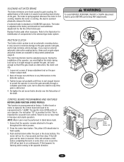
MOTOR LEARN FUNCTION (FORCE PROFILE)...brake minimizes over the flat portion of torque adjustment nut on SL585/595 operators. The clutch mechanism must be performed in improper... set screws of the shaft.
If either the open /close buttons. Press the motor learn or some other error ...
SL595 Manual - Page 29
...OPEN
(OR)
7 HARD OPEN
(GN)
8 INTERRUPT (SAFETY)
OBS. Wire color: 115V black, 208V red, 230V orange.
3. When using a remote control or Single Button Control Station in lieu of the Soft Open...DIRECTION INTERCHANGE
PURPLE & GRAY WIRES ON MODEL SL585
OR THE RED & GREEN WIRES ON ...SOFT OPEN J1-6
HARD OPEN J1-7
INT. Transformer primary voltage same as operator line voltage 24V secondary 60VA....
SL595 Manual - Page 33
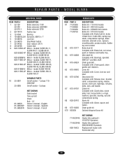
...handle. Disconnect kit Complete with thermostat only
33 models SL585-100-23,
SL585-100-43, SL585-100-83
K20-3100M-5 Motor - models SL585-50-11,
SL585-50-21, SL585-50-81
K20-3050C-4P Motor - Alarm kit ...50B12LGH Sprocket, 50B12 x 1"
5 10-30678
Lock bar
6 23-34815
Stop/Reset button
7 32-34792
Gear reducer (30:1)
8 39-34786
Clutch disk
9 K20-1050C-2P Motor -
Clutch kit Complete...
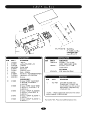
SL595 Manual - Page 35

... located on enclosure door
ITEM PART # K1...
Pillowblock bearing
18 39-10541
Clutch disk
23-34815
NOT SHOWN
Stop/Reset button - Disconnect kit Complete with : Brake hub kit, brake release lever, ..., spacer and faston. Clutch kit Complete with: Clutch, pressure plate, torque limiter sprocket assembly, bell washer 3" ODX 1-1/2", nut 1-1/2" hex jam, clutch disc and 1/4 X 1-1/2 key. models SL595...
SL595 Manual - Page 37
... RPM Sensor (Hall Effect)
ITEM K1
PART #
SERVICE KITS DESCRIPTION
K72-34818
Limit shaft kit (SL585 only) Complete with: Limit shaft, limit nuts, limit bearings, limit sprocket, shim washers, compression...25-2008
25-2010
25-2015
25-2025
DESCRIPTION Limit nut Limit switch (SL585 only) Contactor Control board Stop switch Open/close switch Radio - 315 MHz Transformer - 120/208/230/460/60VA ...
Similar Questions

Code D24 On Lifmaster Sl585 Gate Opener.... Bench Test Only Not Yet Installed
Everything else running fine, what do i need to connect to clear code
Everything else running fine, what do i need to connect to clear code
(Posted by natcoltd1 1 year ago)

Lift Master Sl585 Sliding Gate Will Not Close After Opening
gate has a code of three flashes . Replaced hall effects . Still gate opens but will not close .
gate has a code of three flashes . Replaced hall effects . Still gate opens but will not close .
(Posted by dsponsler 5 years ago)

Will A Door Bell Switch Work For A Garage Door Push Button
(Posted by fedppoli 10 years ago)

How Do I Program Liftmaster Sl595 To Open And Close Using Keypad Entry?
is this possible? want a pin to open and close gate.. dont want pushbuttons or remote.
is this possible? want a pin to open and close gate.. dont want pushbuttons or remote.
(Posted by Bourked 11 years ago)
How To Wire Stop/open/close Push Buttons To Ternimal Strip Of Liftmaster Sl585
(Posted by agresti 12 years ago)