Intel BOXD845HV Support Question
Intel BOXD845HV Support Question
Find answers below for this question about Intel BOXD845HV - 845 Pga478 Max-3GB Sdr Matx3pci Agp4x Cnr Snd Ata100 400mhz.Need a Intel BOXD845HV manual? We have 1 online manual for this item!
Question posted by thoniocimino on November 9th, 2014
Scsi Led
The Conector LED SCSI is for Input or Output ?
Current Answers
Related Intel BOXD845HV Manual Pages
Product Specification - Page 5
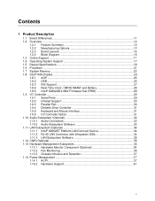
...Operating System Support 17 1.5 Design Specifications 18 1.6 Processor ...21 1.7 System Memory ...22 1.8 Intel® 845 Chipset...24 1.8.1 AGP ...25 1.8.2 USB...25 1.8.3 IDE Support 27 1.8.4 Real-Time Clock, CMOS SRAM,... Connect Device 34 1.11.2 RJ-45 LAN Connector with Integrated LEDs 34 1.11.3 LAN Subsystem Software 35 1.12 CNR (Optional) ...35 1.13 Hardware Management Subsystem 36 1.13.1 ...
Product Specification - Page 7

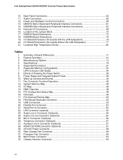
Intel 845 Chipset Block Diagram 24 5. ICH2 and CNR Signal Interface 35 9. USB Port Configuration for Boards with the SMSC LPC47M132 I /O Controller ..........26 6. Audio Subsystem Block Diagram 32 8. Contents
3.8 ...Optional 126 5.5 BIOS Beep Codes ...126
Figures
1. D845HV Board Components 14 2. Block Diagram ...16 4. Location of the Optional Standby Power Indicator LED 44
vii
Product Specification - Page 8
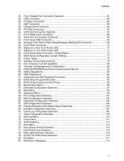
... Dimensions 74 18. I /O Shield Dimensions (for boards without the LAN Subsystem 77 21. Summary of the Jumper Block 72 17. Supported Processors 21 6. LAN Connector LED States 34 8. Fan Connector Function/Operation 42 12. System Memory Map 45 13. PCI Configuration Space Map 48 16. Parallel Port Connector 53 21. Audio...
Product Specification - Page 9
...38. PCI IDE Connectors 67 40. SCSI LED Connector (Optional 67 41. Standby Current Requirements 79 52. Thermal Considerations for a One-Color Power LED 71 47. Supervisor and User Password ...Submenu 115 78. Peripheral Configuration Submenu 102 67. Diskette Configuration Submenu 107 70. CNR Connector ...63 36. Maintenance Menu ...96 61. Front Panel Audio Connector 69 42...
Product Specification - Page 11
...Online Support ...17 1.4 Operating System Support 17 1.5 Design Specifications 18 1.6 Processor ...21 1.7 System Memory ...22 1.8 Intel® 845 Chipset...24 1.9 I/O Controller ...29 1.10 Audio Subsystem (Optional 32 1.11 LAN Subsystem (Optional 34 1.12 CNR (Optional) ...35 1.13 Hardware Management Subsystem 36 1.14 Power Management 37
1.1 Board Differences
This TPS describes these boards...
Product Specification - Page 13

... detect out of range thermal values
• Two fan sense inputs used to monitor fan activity
The items listed below are mutually ...the audio subsystem (described on page 32) • Delete the SCSI hard drive activity LED connector (shown on pages 61 and 62) • Delete the ... 2.2 • Suspend to RAM support • Wake on PCI, CNR, RS-232, front panel, PS/2 devices, and USB ports
For ...
Product Specification - Page 28
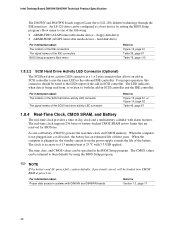
..., custom defaults, if previously saved, will be specified in SCSI controller. For proper operation, this connector should be configured as the onboard IDE controller. The real-time clock supports 256 bytes of the IDE connectors BIOS Setup program's Boot menu
Refer to the LED output of the following:
• ARMD-FDD (ATAPI removable...
Product Specification - Page 34

.... The Intel 82562ET provides the following functions:
• Basic 10/100 Ethernet LAN connectivity • Supports RJ-45 connector with status indicator LEDs on the
CNR bus • PCI Power Management
Supports ACPI technology Supports LAN wake capabilities
1.11.1 Intel® 82562ET Platform LAN Connect Device
The Intel 82562ET ...
Product Specification - Page 43

...) sleep-state. The use of providing adequate +5 V standby current. The optional standby power indicator LED shows that also support this specification, see Section 1.5. Figure 9 shows the location of this specification....
43 Table 10 on the versions of the optional standby power indicator LED. For information on page 40 lists the devices and events that can participate...
Product Specification - Page 44

Location of the Optional Standby Power Indicator LED
1.14.2.5 Resume on Ring The operation of Resume on Ring can be summarized as follows: • Resumes operation from ACPI S1 or S3 states • ...
Product Specification - Page 51

..., and Mic in) • Internal I/O connectors (see page 55) Audio (telephony, auxiliary line input, and ATAPI CD-ROM) Fans Power Add-in boards (CNR, PCI, and AGP) IDE Diskette drive SCSI LED • External I/O connectors (see page 68) Front panel audio Front panel USB ...
Product Specification - Page 55

... with the slot closest to an actual slot location on the D845HV board; The CNR slot shares an ATX expansion; The ATX/MicroATX specifications identify expansion slot locations with ... 6 on the D845WN board) AGP IDE (two) Diskette drive SCSI LED
2.8.2.1 Expansion Slots The board has the following functional groups: • Audio (see page 56)
...
Product Specification - Page 61

... to pin A41
A B C DE
40
2
1
39
40
1
2
1
2
34
1
33
39
Item A B C D E F G H I
I
H
G
Description Communication and networking riser (CNR) PCI bus connector 3 PCI bus connector 2 PCI bus connector 1 AGP connector Diskette drive Primary IDE Secondary IDE SCSI LED (Optional)
F
OM11432
For more information see: Table 35 Table 36 Table 36 Table 36 Table 37 Table...
Product Specification - Page 62

...
40
2
1
39
40
1
2
1
2
34
1
33
39
L
K
J
I
Item A B C D E F G H I J K L
Description Communication and networking riser (CNR) PCI bus connector 6 PCI bus connector 5 PCI bus connector 4 PCI bus connector 3 PCI bus connector 2 PCI bus connector 1 AGP connector Diskette drive Primary IDE Secondary IDE SCSI LED (Optional)
For more information see: Table 35 Table 36 Table 36 Table...
Product Specification - Page 67

Technical Reference
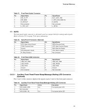
Table 39. SCSI LED Connector (Optional)
Pin
Signal Name
1
SCSI_ACT#
2
No connect
67 Table 40. PCI IDE Connectors
Pin Signal Name
Pin Signal Name
1
Reset IDE
2 Ground
3
Data 7
4 Data 8
5
...
Product Specification - Page 68

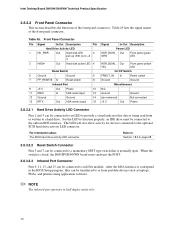
External I /O connectors.
A
12 9 10
7 10
15
2 1
1
16
21
12 8 9
Item A B C
D E
E DC
Description Front panel audio Serial Port B (optional) Auxiliary front panel power/sleep/message-waiting LED (optional) Front panel Front panel USB
B
OM11434
For more information see: Table 41 Table 42 Table 44
Table 45 Table 43
Figure 15. Intel Desktop ...
Product Specification - Page 69
...
Signal Name
1
USB_FNT_PWR
3
USB_FNTA#
5
USB_FNTA
7
Ground
9
Not connected
Pin
Signal Name
2
USB_FNT_PWR
4
USB_FNTB#
6
USB_FNTB
8
Ground
10
Not connected
2.8.3.1 Auxiliary Front Panel Power/Sleep/Message-Waiting LED Connector (Optional)
Pins 1 and 3 of the front panel connector. Table 44. Refer to Send) Not connected
Table 43. Technical Reference
Table 41.
Product Specification - Page 70
...Pins 9, 11, 13, and 15 can be connected to the optional SCSI hard drive activity LED connector.
For the LED to function properly, an IDE drive must be connected to an IrDA ...
IrDA serial input
12
13 Ground
Ground
14
15 IRTX
Out IrDA serial output
16
Signal
In/Out Description
Power LED
HDR_BLNK_ Out GRN
Front panel green LED
HDR_BLNK_ Out YEL
Front panel yellow LED
On/Off ...
Product Specification - Page 71

... off /sleeping
Steady Green
Running
Blinking Green
Running/message waiting
Table 47. States for a one - Table 47 shows the possible states for a One-Color Power LED
LED State
Description
Off
Power off
Steady Green
Running
Blinking Green
Running/message waiting
Steady Yellow
Sleeping
Blinking Yellow
Sleeping/message waiting
NOTE
To use the...
Product Specification - Page 91
... LS-120 diskette (in flash memory. For information about The Intel World Wide Web site
Refer to the speaker or looking at the diskette drive LED. • The recovery process may take several minutes; You can be programmed into the flash memory using the BIOS recovery mode.
The BIOS can only...
Similar Questions

Intel D865perl Front Panel Switch Wiring On Mother Board, Power Led, Hdd Led
Need help to find the pins on my D865PERL mother Board for the power LED, Hard Drive Activity LED
Need help to find the pins on my D865PERL mother Board for the power LED, Hard Drive Activity LED
(Posted by GartK348 8 years ago)

Hdd Led On
hdd led in motherboard intel dx58so always on not blinking, cpu can't boot to windows . in monitor o...
hdd led in motherboard intel dx58so always on not blinking, cpu can't boot to windows . in monitor o...
(Posted by stcandra 8 years ago)

Boot Failure With Wd Fire Led Glows
Following is the phases of MB behaviour: System has been switched ON. All Fans have been started spi...
Following is the phases of MB behaviour: System has been switched ON. All Fans have been started spi...
(Posted by prasad28068 10 years ago)

Mother Board Led Keeps Blinking And Pc Does Not Turn On
MOTHER BOARD LED KEEPS BLINKING AND PC DOES NOT TURN ON
MOTHER BOARD LED KEEPS BLINKING AND PC DOES NOT TURN ON
(Posted by smartshariff 11 years ago)

Led Indicators On Board
Unless I do a hard reset on the motherboard, the OS SATA LED 10(+5v) is red and the CPU is green, al...
Unless I do a hard reset on the motherboard, the OS SATA LED 10(+5v) is red and the CPU is green, al...
(Posted by nevrsummer 11 years ago)