Hitachi C10FSB Support Question
Hitachi C10FSB Support Question
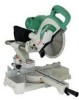
Find answers below for this question about Hitachi C10FSB - 10 Inch Sliding Dual Bevel Compound Miter Saw.Need a Hitachi C10FSB manual? We have 2 online manuals for this item!
Question posted by workmastersinc on January 18th, 2017
Controller
can i bypass controller by rewiring since you can not get item
Current Answers
Answer #1: Posted by hzplj9 on January 18th, 2017 1:23 PM
hzplj9

Member since:
June 25th, 2012 Points: 4,873,510

Member since:
June 25th, 2012 Points: 4,873,510
You can obtain a new controller here:
https://www.amazon.com/Hitachi-321354-Controller-C10FSB-Replacement/dp/B00O91NSVY
It is not cheap though. You would need to rewire the unit and have no speed control if you overide this.
Hope that helps.
Related Hitachi C10FSB Manual Pages
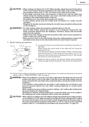
Instruction Manual - Page 4

... the risk of the blade in order to provide support for descriptions of the slide
compound saw.
25. ALWAYS USE EYE PROTECTION WHEN WORKING WITH THE TOOL TO PREVENT EYE INJURY. Always keep proper footing and balance when working with the saw blade from binding and other components for damage before attempting to be used...
Instruction Manual - Page 5
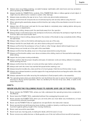
... the saw . 17. During miter or bevel cutting, always wait for the rotation of extension cords are mounted properly and securely before beginning a cut . 22. Always wait until the motor has reached full speed before attempting
slide cutting.
18. Always use of the saw blade.
12. Never remove any abnormality whatsoever. 6. Always handle the POWER TOOL...
Instruction Manual - Page 6
...disconnect power before using the slide compound saw blade to warning sign " " while the tool is being operated. REPLACEMENT PARTS
When servicing use the POWER TOOL near flammable liquids or ...on and off tool and wait for saw blade. 3. Saw blade diameter is 3800/min. 10. No load speed is 10" (255mm). 9. Never use only identical replacement parts. Never operate the saw without the guards...
Instruction Manual - Page 8

... safe operation
and maintenance of the power tool.
NAME OF PARTS
MODEL C10FSH/MODEL C10FSB
Dust Bag Hinge
Gear Case Motor Head Moter
Handle Spindle Cover
Holder (A)
Saw Blade
Indicator (For right bevel scale)
Leser Marker (Only C10FSH) Vise Assembly
Safety Cover
Rotation Direction
Fence (A)
Indicator (For miter scale) Table Insert
Fence (B)
Sub Fence Fig...
Instruction Manual - Page 9

English
SPECIFICATIONS
Item
Model
C 10FSH / C 10FSB
Motor
Type
Series commutator motor
Power source
Single-phase AC 60Hz
Voltage (Volts)
120
Full-load current (Amp)
12
Laser Marker Maximum output
Instruction Manual - Page 13

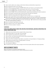
...10-b) Furthermore, when changing the position of both ends. Positioning the table insert
6mm Machine Screw
Workpiece
Saw Blade
6mm Machine Screw
Table insert
Workpiece Saw Blade Table insert
Workpiece Saw Blade Table insert
6mm Machine Screw
[Right angle cutting] Fig. 9-a
[Left bevel angle cutting] Fig. 9-b
[Right bevel...that the saw blade can be minimum. When shipping the tool from ...
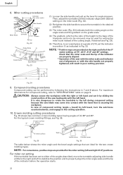
Instruction Manual - Page 14

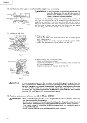
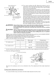
... Wing Nut Fig. 10-b
4.
In the case of left (counterclockwise) as viewed from behind of the tool.
(3) Turn the 8mm depth adjustment bolt, change the height where the bolt head and the gear case contacts, and adjust the lower limit position of the saw blade.
Left bevel angle cutting
Right bevel angle cutting Direct angle...
Instruction Manual - Page 16
...176; to the right or more, please slide the guard to the guard.
12. If the switch trigger is pulled inadvertently, the saw blade can realize stable cutting of the ...compound cutting (Miter cutting + bevel cutting) Upon lowering the motor section, the safety cover is plugged into the holes in unexpected accidents. * Do not remove the laser marker to secure the sub fence (A). English
10...
Instruction Manual - Page 17

... to the laser marker (main body of factory shipment. Adjust the positions of the saw blade at the time of tool); otherwise, the cord may come off and the laser marker may not be hurt.... * Do not dismantle it may result in a shortened service life. * Use of controls or adjustments or performance...
Instruction Manual - Page 19

... the height of the workpiece.
CAUTION: Always confirm that the power tool cannot be raised or lowered
6mm Knob Bolt
Knob
according to the lower surface of the screw holder. For other compound cutting (left bevel + right miter, right bevel + left side of the saw blade. Cutting Operation
a Adjusting Line b
(1) As shown in the handle, serious...
Instruction Manual - Page 20

...of the turntable, and then proceed to page 9 "SPECIFICATIONS" for 10 minutes or so, and then restart your cutting operation.
4. Then ...cut material from the workpiece. Press Down
Using the power tool this case, mount an auxiliary board with the 6mm flat... can be done depending on the handle and slide the saw blade is raised while the saw blade back to scatter about dangerously. * Every...
Instruction Manual - Page 21
... completely before raising the handle from the workpiece. If the handle is raised while the saw blade is pressed down gently and carefully. * In slide cutting, gently push the handle back (rearwards) in Fig. 30. When stopping the bevel cutting operation halfway, start cutting after each crosscut operation in the right 45°...
Instruction Manual - Page 22
... used for setting the miter scale instead of the saw backwards with the hand that are provided for the two crown molding types. Crown molding cutting procedures
Fig. 35 shows two common crown molding types having angles of compound cutting (angle + bevel) by following the instructions in the cutting operation.
10. A upper surface Ceiling
Ceiling...
Instruction Manual - Page 23
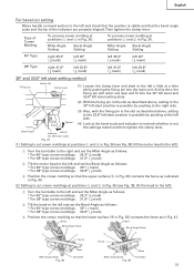
... left a little at positions 2 and 3 in Fig. 36. At this time, the fixing pin will enter one step and fit into the main unit.
Miter Angle Setting
Bevel Angle Setting
To process crown molding at a time while pushing the fixing pin into the 30° left slant and 33.9° left slant...
Instruction Manual - Page 24
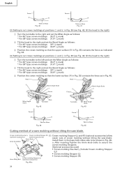
...molding without tilting the saw blade. Install them in Fig. 45. tilt the head to the right):
1 Turn the turntable to the left and set the Bevel Angle as follows:...Bolt (optional accessories)
Fig. 46-a
24 Head
Head
4 Bevel Angle Scale
Bevel Angle Scale
1
3
2
Fence
Fence
Miter Angle Scale
Base Turntable
Fig. 42
Turntable
Base
Miter Angle Scale
Fig. 43
Fence
B
A
Table on Base Fig...
Instruction Manual - Page 25
... the table and cause bodily harm. Position crown molding with saw blade. Cutting depth adjustment procedure:
(1) Loosen the 8mm wing... molding
vise ass'y when it is lowered for the miter angle. Position in Fig. 34
Miter angle
Finished piece
For inside corner
1
Right 45°... by hand.
25 Do not bevel cutting.
Then turn the upper knob, as shown in Fig. 46-b.
...
Instruction Manual - Page 26

... out of the workpiece and tighten it using tools other than normal during bevel cutting. Sawdust will accumulate more quickly than the...after the adjustment has been completed. Mounting the saw blade rotates.
SAW BLADE MOUNTING AND DISMOUNTING
WARNING: * To prevent...can get damaged, resulting in injuries. Duct
(2) During bevel and compound cutting, attach the dust bag at either end of...
Instruction Manual - Page 29

...soapy cloth. Lubrication
Lubricate the following sliding surfaces once a month to keep the power tool in the guard may widen and... (B)
Fig. 56
10. To assure that only authorized replacement parts will be protected, all 10 teeth of the power tool, especially from contact ... Model C10FSH) If the laser line becomes invisible due to the saw blade by loosening the two 5mm screws (see Fig. 1 and...
Parts List - Page 1

E933
ELECTRIC TOOL PARTS LIST
SLIDE COMPOUND SAW Model C 10FSB
2004 • 2 • 13 (E2)
1 2 3 4 56 7
40 41
8 9 10 11 12
14 15 16 13 17 18 19 20
21 22 23 24
25
26
27 28 29 30 29
31 32 33 9 10 35 34 10 9 36
37 38 39
601
603 602 618
604
605 602...
Parts List - Page 6

...) D5X25 (BLACK) 3
126 321-355 SHEET
1
* 127 321-354 CONTROLLER 100V-120V
1
* 127 322-200 CONTROLLER 220V-240V
1
128 930-804 TERMINAL M4.0 (10 PCS.)
1
129 321-393 HANDLE (R)
1
130 301-653 131 880-...620-1VV BALL BEARING 6201VVCMPS2L
1
141 307-731 COVER
1
142 949-322 FLAT HD. PARTS
ITEM NO. SCREW M4X10 (10 PCS.)
2
143 321-357 PULLEY (B)
1
144 307-736 BELT (170H10)
1
* 145...
Similar Questions

That's The Original Hitachi Japonês?
I'm looking for hitachi miter saw 10" japonês original not the metabo you guys have
I'm looking for hitachi miter saw 10" japonês original not the metabo you guys have
(Posted by Pereirafulr 2 years ago)

Do You Know How I Can Rewire Dont Care About Speed Control
(Posted by workmastersinc 7 years ago)
How To Adjust Cut Depth Hitachi 10 Compound Miter Saw Manual
(Posted by dbrag 9 years ago)

Where Can I Get A Free Manual On The Hitachi C12rsh 12' Slide Compound Miter Saw
(Posted by kathy86883 14 years ago)