HP CP3525dn Support Question
HP CP3525dn Support Question
Find answers below for this question about HP CP3525dn - Color LaserJet Laser Printer.Need a HP CP3525dn manual? We have 35 online manuals for this item!
Question posted by michahe on August 9th, 2014
How To Replace A Fuser Drive Assembly On A Hp 3525
The person who posted this question about this HP product did not include a detailed explanation. Please use the "Request More Information" button to the right if more details would help you to answer this question.
Current Answers
Related HP CP3525dn Manual Pages
HP Color LaserJet CP3525 Series Printers - User Guide - Page 190
...coverage of using a non-HP supply. Order a replacement print cartridge. Estimated pages remaining is using non-HP or unauthorized supplies is full...replacement fuser kit. Order a replacement toner collection unit now. No action is nearly full.
The toner collection unit is necessary. Please wait until a supply needs to retrieve.
The fuser is being performed.
The color...
HP Color LaserJet CP3525 Series Printers - User Guide - Page 192
... specified color cartridge. Wait for the fuser to remove it .
1. Replace the fuser
1.
REPLACE SUPPLIES For status press OK
Two or more information about the REPLACE SUPPLIES menu, see System setup menu on page 27. Or, configure the product to continue printing by using the REPLACE SUPPLIES menu.
After an HP supply has reached its useful life. product...
Service Manual - Page 11

... motor 286
Main-drive assembly ...287 Remove the main-drive assembly 288 Reinstall the main-drive assembly 292
Fuser-drive assembly ...298 Remove the fuser-drive assembly 299 Reinstall the fuser-drive assembly 302
Delivery assembly ...303 Remove the delivery assembly 304 Reinstall the delivery assembly 307
Duplex-drive assembly ...308 Remove the duplex-drive assembly 309
Optional paper...
Service Manual - Page 25

...6-211 Remove the fuser-drive assembly (1 of 6 299 Figure 6-212 Remove the fuser-drive assembly (2 of 6 299 Figure 6-213 Remove the fuser-drive assembly (3 of 6 300 Figure 6-214 Remove the fuser-drive assembly (4 of 6 300 Figure 6-215 Remove the fuser-drive assembly (5 of 6 301 Figure 6-216 Remove the fuser-drive assembly (6 of 6 301 Figure 6-217 Reinstall the fuser-drive assembly 302 Figure...
Service Manual - Page 192

HP does not support repairing individual subassemblies or troubleshooting to tighten. Frayed or pinched harness wires can be removed to service the product.
Removal and replacement strategy
WARNING!
If a self-tapping screw-hole becomes stripped, repair the screw-hole or replace the affected assembly...protective cover removed from the laser/scanner assembly. Be careful when handling ...
Service Manual - Page 320

... Reinstall the main-drive assembly (2 of 11)
1
3
2
2. Figure 6-200 Reinstall the main-drive assembly (1 of 11)
4
292 Chapter 6 Removal and replacement
ENWW Install the bracket and guides on the assembly (this motor must be removed from the assembly to align the main-drive cams). NOTE: Do not install the developing-disengagement motor on the replacement main-drive assembly. Remove the bracket...
Service Manual - Page 326
... from the rear cover to remove the fuser-drive assembly. ● Front-top cover. See Front-top cover on page 186. ● Right-rear cover.
See Low-voltage power supply on page 175. ● Fuser. See Formatter PCA on page 243. ...See DC controller PCA and tray on page 287.
298 Chapter 6 Removal and replacement
ENWW See Main-drive assembly on page 240. ● Low-voltage power supply.
Service Manual - Page 327
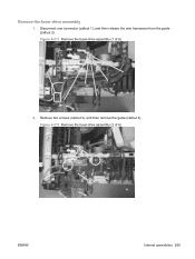
Figure 6-211 Remove the fuser-drive assembly (1 of 6)
3
4
ENWW
Internal assemblies 299 Figure 6-212 Remove the fuser-drive assembly (2 of 6)
2 1
2. Remove the fuser-drive assembly
1. Remove two screws (callout 3), and then remove the guide (callout 4). Disconnect one connector (callout 1), and then release the wire harnesses from the guide (callout 2).
Service Manual - Page 328
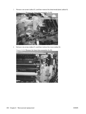
Remove one screw (callout 7), and then remove the cover (callout 8). Remove one screw (callout 5), and then remove the sheet-metal plate (callout 6). 3. Figure 6-213 Remove the fuser-drive assembly (3 of 6)
8
7
300 Chapter 6 Removal and replacement
ENWW Figure 6-214 Remove the fuser-drive assembly (4 of 6)
6 5
4.
Service Manual - Page 329
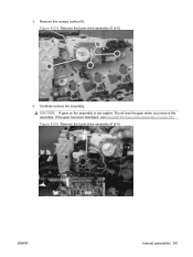
If the gear becomes dislodged, see Reinstall the fuser-drive assembly on the assembly is not captive. Figure 6-216 Remove the fuser-drive assembly (6 of 6)
9
6. Carefully remove the assembly. Remove five screws (callout 9). CAUTION: A gear on page 302. Do not lose the gear when you remove the assembly. 5. Figure 6-215 Remove the fuser-drive assembly (5 of 6)
ENWW
Internal ...
Service Manual - Page 330
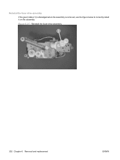
Reinstall the fuser-drive assembly If the gear (callout 1) is dislodged when the assembly is removed, use the figure below to correctly install it on the assembly. Figure 6-217 Reinstall the fuser-drive assembly
1
302 Chapter 6 Removal and replacement
ENWW
Service Manual - Page 331
... supply upper. See High-voltage power supply lower (HVPS-D) on page 211. ● Power-supply fan and fan duct. See Fuser-drive assembly on page 179. ● Secondary transfer assembly. ENWW
Internal assemblies 303 See Fuser on page 298. See High-voltage power supply upper (HVPS-T) on page 230. ● Interconnect board (ICB). NOTE: It is...
Service Manual - Page 336
... Chapter 6 Removal and replacement
ENWW See Delivery assembly on page 230. ● Interconnect board (ICB). See Intermediate transfer belt (ITB) on page 203 ● Rear cover and upper-rear cover. See Control-panel assembly on page 188. ● Right-rear cover. See Secondary transfer assembly on page 298. ● Delivery assembly. See Fuser-drive assembly on page 186...
Service Manual - Page 443
... sensor is letter F in the sensor test. If the value does not change, replace paper delivery assembly.
ENWW
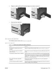
Clear paper jams 415 Close the lower right door. Jam causes and solutions
...303. See Delivery assembly on page 353.
If paper is damaged
Replace the paper delivery assembly. Jams in the actuator-drive mode. If the motor is defective
Execute the fuser-motor driving test in the...
Service Manual - Page 446
...mode to verify that the TOP sensor is not, replace the cassette-pickup drive assembly. Reconnect the following corresponding part:
● TOP sensor (SR8): Replace the registration assembly.
Replace the following corresponding sensor connector:
● TOP sensor (SR8): Connector (J109) on the DC controller PCA
● Fuser delivery sensor (SR5): Intermediate connector (J95) and connector...
Service Manual - Page 447

...Replace the ITB.
Replace the delivery assembly. Run the pickup motor drive test in correct position. If the motor is worn or deformed Replace the duplex feed unit.
See Registration assembly on page 188. The spring of media
Replace...pad are worn or deformed, replace any defective parts. Jams in the duplex area (HP Color LaserJet CP3525dn and HP Color LaserJet CP3525x only)
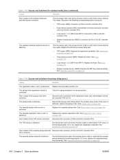
Table 7-21 ...
Service Manual - Page 464

... misformed characters. Check each drive gear between the ITB drive roller and the ITB motor. The RD sensor is defective.
Replace the laser/scanner assembly.
See Laser/scanner assembly (Y/M) on page 265 or Laser/scanner assembly (C/Bk) on the printed page" row in the
is deformed.
Replace the laser/scanner assembly.
correct position.
Clean the fuser inlet guide.
Service Manual - Page 553

...
output bins 4 cartridges
non-HP 81 ordering through embedded
Web server 76 removing 170 replacement intervals 81 storage 81 warranty 509 cartridges, print error messages 385 part numbers 447 cassette lift operation 141, 158 paper-level detection 143
paper-presence detection 143, 159
pickup assembly, removing 263
pickup drive assembly, removing 256
pickup operations 140...
Service Manual - Page 556

... 10 Korean EMC statement 523
L LAN-connector 4 languages, printer 4 laser safety statements 523 laser/scanner
assembly (C/Bk), removing 272
assembly (Y/M), removing 265
failure conditions 120 operations 119 last rotation period 105 latent image formation 122 LEDs. See lights left cover, removing 200 license, software 511 lifter-drive assembly removing 254 light print, troubleshooting 432 lights...
Service Manual - Page 559

... 193 front-top cover 208 fuser 179 fuser motor 285 fuser-drive assembly 298 high-voltage power supply
lower 248 high-voltage power supply
upper 279 interconnect board (ICB) 238 intermediate transfer belt 188 laser/scanner assembly (C/
Bk) 272 laser/scanner assembly (Y/
M) 265 left cover 200 lifter-drive assembly 254 low-voltage power supply 243 main-drive assembly 287 memory DIMM 176 pickup...
Similar Questions

50.2 Fuser Error In Hp Laserjet P4015x
50.2 fuser error in hp laserjet p4015x how to rectify this error
50.2 fuser error in hp laserjet p4015x how to rectify this error
(Posted by fakharaltaf01 2 years ago)

Hp Color Laserjet Cp3525x How To Replace The Main Drive Assembly Kit
(Posted by ECglen 9 years ago)

How To Clear The Display Message In A Hp 3525 Color
(Posted by DYMboobl 9 years ago)

How To Replace Fuser Kit For Hp 4650
(Posted by kaysu 10 years ago)

How To Reset Fuser Count On Hp 3525
(Posted by cuazh 10 years ago)