Dell PowerEdge T110 Support Question
Dell PowerEdge T110 Support Question
Find answers below for this question about Dell PowerEdge T110.Need a Dell PowerEdge T110 manual? We have 6 online manuals for this item!
Question posted by boiwfry on April 23rd, 2014
The Orange Light That Is Blinking On Poweredge T110 In The Front Panel How To
fix
Current Answers
Answer #1: Posted by JCatDell on April 24th, 2014 12:43 PM
JCatDell

Member since:
March 11th, 2014 Points: 136,220

Member since:
March 11th, 2014 Points: 136,220
Hi,
An amber light could be a few different things. Does it boot to the OS? What do the diagnostic LEDs show? Page 105 of the manual starts the troubleshooting section ftp://ftp.dell.com/Manuals/all-products/esuprt_ser_stor_net/esuprt_poweredge/poweredge-t110_Owner%27s%20Manual_en-us.pdf
Josh Craig
Dell | Social Outreach Services - Enterprise
Get Support on Twitter @DellCaresPro
Related Dell PowerEdge T110 Manual Pages
Getting Started Guide - Page 3
Dell™ PowerEdge™ T110 Systems
Getting Started With Your System
Regulatory Model E11S Regulatory Type E11S001
Getting Started Guide - Page 4

Trademarks used in this text: Dell, the DELL logo, and PowerEdge are not followed.
Dell Inc. A00
SUSE is strictly forbidden. ...; disclaims any manner whatsoever without notice. © 2009 Dell Inc. Microsoft, Hyper-V, Windows, and Windows Server are registered trademarks of Intel Corporation in any proprietary interest in the United States and/or other countries; Other...
Getting Started Guide - Page 7
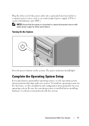
NOTE: Ensure that ships with your operating system. The power indicator should light.
Getting Started With Your System
5
Complete the Operating System Setup
If you purchased a preinstalled operating system, see the installation and configuration documentation for better performance. ...
Hardware Owner's Manual - Page 2

... in this document is strictly forbidden.
Dell Inc.
All rights reserved. Microsoft, Windows, Windows Server, and MS-DOS are not followed. August 2009
Rev. is subject to change without the written...Reproduction of Dell Inc. Trademarks used in this text: Dell, the DELL logo, and PowerEdge are trademarks of data if instructions are either the entities claiming the marks and names or...
Hardware Owner's Manual - Page 3
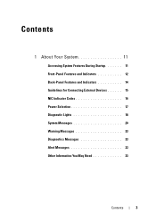
Contents
1 About Your System 11
Accessing System Features During Startup 11 Front-Panel Features and Indicators 12 Back-Panel Features and Indicators 14 Guidelines for Connecting External Devices 15 NIC Indicator Codes 16 Power Selection 17 Diagnostic Lights 18 System Messages 20 Warning Messages 33 Diagnostics Messages 33 Alert Messages 33 Other Information You...
Hardware Owner's Manual - Page 7
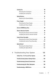
... Memory Key 95
Chassis Intrusion Switch 96 Removing the Chassis Intrusion Switch 96 Installing the Chassis Intrusion Switch 97
Control Panel Assembly 98 Removing the Control Panel Assembly 98 Installing the Control Panel Assembly 100
System Board 101 Removing the System Board 101 Installing the System Board 102
4 Troubleshooting Your System 105
Safety...
Hardware Owner's Manual - Page 12
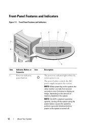
... and Indicators
Figure 1-1. The power button controls the DC power supply output to the system is on. Front Panel Features and Indicators
1
2
3
4
7 6
Item Indicator, Button, or Icon Connector
1
Power-on indicator,
power ...take from several seconds to over 2 minutes to display an image, depending on indicator lights when the system power is turned off.
12
About Your System
Hardware Owner's Manual - Page 13

... page 18. About Your System
13 The four diagnostic indicator lights display error codes during system startup. One optional SATA DVD-ROM ...One optional half-height (using one drive bay). NOTE: DVD devices are USB 2.0-compliant.
The hard drive activity indicator lights up when the hard drive is detected. Connects USB devices to the system.
Item Indicator, Button, or Icon Connector
...
Hardware Owner's Manual - Page 14
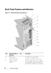
Back-Panel Features and Indicators
1 2
3
4 5
6 7 8 9 10 11
Item Indicator, Button, or Icon Connector
1
Padlock ring
2
Security cable slot
3
Voltage selection
switch
Description
Locks the cover release ... voltage for the power supply to the voltage that most closely matches the AC power available at your location
14
About Your System Back-Panel Features and Indicators
Figure 1-2.
Hardware Owner's Manual - Page 16
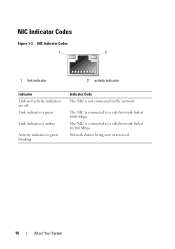
... Indicator Codes
1
2
1 link indicator
2 activity indicator
Indicator Link and activity indicators are off Link indicator is green
Link indicator is amber
Activity indicator is green blinking
Indicator Code The NIC is being sent or received.
16
About Your System
Hardware Owner's Manual - Page 17
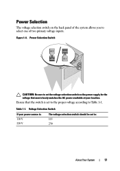
... matches the AC power available at your power source is set to the proper voltage according to set the voltage selection switch on the back panel of the system allows you to : 115 230
About Your System
17 Voltage Selection Switch
If your location.
Figure 1-4.
Ensure that the switch is : 110...
Hardware Owner's Manual - Page 18
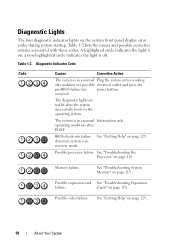
... Code
Code
Causes
Corrective Action
The system is on; See "Getting Help" on the system front panel display error codes during system startup.
Possible expansion card See "Troubleshooting Expansion
failure. a non-highlighted circle indicates the light is in recovery mode. occurred. See "Troubleshooting the Processor" on page 118. The system is off...
Hardware Owner's Manual - Page 61
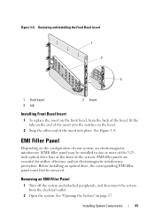
... into the notches on page 57.
Before installing an optical drive, the corresponding EMI filler panel must first be installed in one or more of the 5.25inch optical drive bays at the...the insert into place. Installing System Components
61 Figure 3-4. See Figure 3-4. Removing an EMI Filler Panel
1 Turn off the system and attached peripherals, and disconnect the system from the back of the...
Hardware Owner's Manual - Page 62
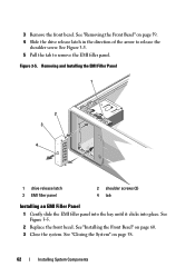
... "Installing the Front Bezel" on page 58.
62
Installing System Components Removing and Installing the EMI Filler Panel
1
2 3
4
1 drive release latch 3 EMI filler panel
2 shoulder screws (2) 4 tab
Installing an EMI Filler Panel
1 Gently slide the EMI filler panel into the bay until it clicks into place. See Figure 3-5. 5 Pull the tab to release the...
Hardware Owner's Manual - Page 66
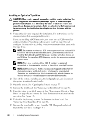
... must have a SCSI controller card installed (see "Removing an Optical or Tape Drive" on page 60.
7 Remove the two shoulder screws from the EMI filler panel and attach them to the cable in between be unterminated. See Figure 3-8.
66
Installing System Components For instructions, see the documentation provided with other devices...
Hardware Owner's Manual - Page 88
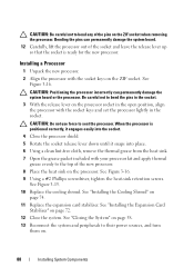
... processor. 8 Place the heat sink on the processor. Installing a Processor
1 Unpack the new processor. 2 Align the processor with the socket keys and set the processor lightly in the socket.
3 With the release lever on the ZIF socket when removing the processor. See Figure 3-16. 9 Using a #2 Phillips screwdriver, tighten the heat-sink...
Hardware Owner's Manual - Page 93

Damage due to the back panel.
8 Press the power-supply release tab down and slide the power supply toward the front of the system.
9 Lift the power-supply out of the ...
Hardware Owner's Manual - Page 94
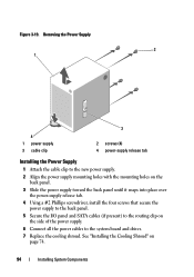
...Align the power supply mounting holes with the mounting holes on the back panel.
3 Slide the power supply toward the back panel until it snaps into place over the power-supply release tab.
4 ... #2 Phillips screwdriver, install the four screws that secure the power supply to the back panel.
5 Secure the I/O panel and SATA cables (if present) to the routing clip on page 74.
94
Installing System...
Hardware Owner's Manual - Page 98
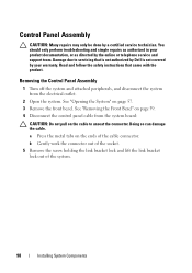
... troubleshooting and simple repairs as authorized in your warranty. See "Opening the System" on page 59. 4 Disconnect the control panel cable from the electrical outlet.
2 Open the system. Removing the Control Panel Assembly
1 Turn off the system and attached peripherals, and disconnect the system from the system board:
CAUTION: Do not pull...
Hardware Owner's Manual - Page 139

... Dell, 129
cooling fan installing, 90 removing, 89 replacing, 90 troubleshooting, 112
D
damaged systems troubleshooting, 109
Dell contacting, 129
Dell PowerEdge Diagnostics using, 121
diagnostics advanced testing options, 123 testing options, 122 using Dell PowerEdge Diagnostics, 121 when to use, 122
DIMM sockets, 80
DVD drive.
Index
139 See CD/DVD drive.
Similar Questions


Why Is The Orange Light Blinking At Behind On Dell Poweredge 2800
(Posted by bmidTheBe 10 years ago)


Suse Installation In Dell Poweredge T110!
I am SO Ratanak. I want to install SUSE Server version 11 operating system to my server PoserEdge T1...
I am SO Ratanak. I want to install SUSE Server version 11 operating system to my server PoserEdge T1...
(Posted by ratanakso 10 years ago)

Lights Blinking
Dell Power Edge 2600-shut down automatically. Upon re-booting, on the front panel, the middle (of th...
Dell Power Edge 2600-shut down automatically. Upon re-booting, on the front panel, the middle (of th...
(Posted by kdemeter 12 years ago)