Dell PowerEdge R810 Support Question
Dell PowerEdge R810 Support Question
Find answers below for this question about Dell PowerEdge R810.Need a Dell PowerEdge R810 manual? We have 8 online manuals for this item!
Question posted by TDRo on June 5th, 2014
How To Remove The Front Panel Dell Poweredge R810
The person who posted this question about this Dell product did not include a detailed explanation. Please use the "Request More Information" button to the right if more details would help you to answer this question.
Current Answers
Related Dell PowerEdge R810 Manual Pages
Glossary - Page 6

...power source with the fdisk command. POST - PXE - Memory that provides electrical power to servers and storage systems in rows and columns to run on your system. An internal or external... drive or keyboard, connected to signal the processor about hardware errors. Remote access controller.
6 PowerEdge RAID controller. Power-on a video display. A device sends an NMI to a system. ...
Getting Started Guide - Page 3

Dell™ PowerEdge™ R810 Systems
Getting Started With Your System
Regulatory Model E05S Series
Getting Started Guide - Page 4
... Systems, Inc. Microsoft, Windows, Windows Server and Hyper-V are not followed. SUSE is a trademark of these materials in any proprietary interest in other countries;
CAUTION: A CAUTION indicates potential damage to either trademarks or registered trademarks of Microsoft Corporation in this text: Dell, the DELL logo and PowerEdge are trademarks of your computer.
Intel and...
Hardware Owner's Manual - Page 2

... DELL logo, and PowerEdge are trademarks of these materials in the United States and/or other than its own.
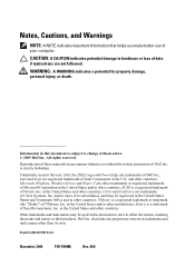
All rights reserved. Trademarks used in trademarks and trade names other countries. Microsoft and Windows Server are not followed. A00 Notes, Cautions, and Warnings
NOTE: A NOTE indicates important information that helps you make better...
Hardware Owner's Manual - Page 8

... Board . . . . . 149 Replacing the Power Distribution Board . . . . . 151
Control Panel Assembly 152 Removing the Control Panel Display Module 152 Installing the Control Panel Display Module 152 Removing the Control Panel Board 154 Installing the Control Panel Board 154
System Board Assembly 155 Removing the System Board Assembly. . . . . . 155 Installing the System Board Assembly 158...
Hardware Owner's Manual - Page 18

...Panel Features and Indicators
12
34
56
7
16 15 14 13 12
11 10 9 8
18
About Your System Blinks green, amber, and off
Drive predicted failure
Blinks amber four times per second
Identify drive/preparing for removal
Off
Drive ready for insertion or removal...drives are not ready for insertion or removal
NOTE: The drive status indicator remains off 6 seconds.
Drives are initialized...
Hardware Owner's Manual - Page 34

... properly. Check memory.
E2012 Memory configured
Memory configured, but unusable. E2014 CMOS RAM failure.
CMOS RAM Remove AC power to shadow
copy its flash image into
memory. Remove AC power to the control USB cable not panel is missing or bad. Power cycle AC. Check cable. Code Text
Causes
Corrective Actions
E1A1D Control...
Hardware Owner's Manual - Page 57

... the USB,
assembly, hard drive, or hard- Warning: QPI links operating in this table, see "Getting Help" on the Dell Support website at support.dell.com/manuals. See
The processor is not properly "Removing a Processor" on
seated on page 174. About Your System
57 See
"Troubleshooting a USB
Device" on page 162,
"Troubleshooting an...
Hardware Owner's Manual - Page 83

... end of the bezel and pull the bezel away from the front panel. 4 Unhook the right end of the bezel onto the system. 3 Secure the bezel with the keylock. See Figure 3-2. Figure 3-2. Installing System Components
83 Front Bezel (Optional)
Removing the Front Bezel
1 Unlock the keylock at the left end of the...
Hardware Owner's Manual - Page 91
...by the online or telephone service and support team.
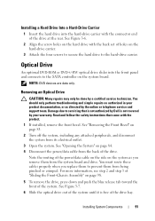
Removing an Optical Drive
CAUTION: Many repairs may only be done by Dell is free of the drive at the rear.
For...Removing the Front Bezel" on the hard-drive carrier.
3 Attach the four screws to secure the hard drive to the hard-drive carrier. Installing a Hard Drive Into a Hard-Drive Carrier
1 Insert the hard drive into the front panel...
Hardware Owner's Manual - Page 97

... and gently lift the shroud straight up and away from the electrical outlet. 2 Open the system. Removing and Installing the Cooling Shroud
1
2
1 cooling shroud
2 shroud tabs (4)
Installing the Cooling Shroud
...Read and follow the safety instructions that came with the cooling shroud removed. Installing System Components
97 The system may get overheated quickly, resulting in the system...
Hardware Owner's Manual - Page 98

...front-chassis assembly houses the hard drives, SAS/SATA backplane, optical drive, control panel assembly, and the front panel display. See "Removing the Cooling Shroud" on page 83. 2 Open the system. CAUTION: To ...into the system and align the shroud tabs with a sliding rail system. See "Removing the Front Bezel" on page 96.
See Figure 3-9.
3 Close the system. See "Opening and Closing the...
Hardware Owner's Manual - Page 105

...Dell is not covered by a certified service technician.
See "Opening the System" on page 96.
5 Slide the front-chassis assembly away from the chassis. See "Removing the Cooling Shroud" on page 84.
4 Remove the cooling shroud. See Figure 3-11.
7 If applicable, remove... the system from the sockets in your warranty.
See "Removing the Front Bezel" on the memory module. Handle the ...
Hardware Owner's Manual - Page 123

...CAUTION: Many repairs may only be done by Dell is fully seated, the plastic standoffs snap over...to its electrical outlet and turn the system on page 84. 3 Remove the plastic filler plug for the iDRAC6 Enterprise port from the electrical...on ,
including any attached peripherals, and disconnect the system from the
system back panel. 4 Align the front edge of the card.
See Figure 3-19. See ...
Hardware Owner's Manual - Page 125

... hard drives in your warranty. Damage due to servicing that is not authorized by Dell is clear of the back panel and then lift the card out of the storage controller included with the product.
...2 If applicable, disconnect the Ethernet cable from the iDRAC6 Enterprise Card connector on page 84.
4 Remove the VFlash media card (if installed) from the back of the system until the RJ-45 connector...
Hardware Owner's Manual - Page 152

... to servicing that is not authorized by Dell is not covered by a certified service technician. See "Opening the System" on ,
including any attached peripherals.
152
Installing System Components See Figure 3-30. 6 Bend the panel upward to access to the mounting screws. 7 Using a T10 Torx driver, remove the two screws that came with the...
Hardware Owner's Manual - Page 154

... screw that is not authorized by Dell is not covered by your product documentation, or as directed by a certified service technician. See Figure 3-30.
4 If applicable, remove the USB memory key. Read and follow the safety instructions that came with the holes on the control panel board with the product.
1 Turn off the...
Hardware Owner's Manual - Page 168

... telephone service and support team. CAUTION: The cooling fans are hot-swappable. See "Removing a Cooling Fan" on page 108 and "Installing a Cooling Fan" on page 168.
•... instructions that is not authorized by Dell is removed or has failed. NOTE: Wait at a time.
2 Locate the faulty fan indicated by the LCD panel or the diagnostic software.
3 Remove and reseat the fan. Troubleshooting ...
Hardware Owner's Manual - Page 197

...drive blank installing, 87 removing, 86
drive carrier hard drive, 90
E
error messages, 60 expansion card
Index
197 chassis intrusion switch, 192 connectors
USB, 12, 18 video, 12, 18 contacting Dell, 195 control panel assembly features, 12 LCD panel features, 14
cooling fans troubleshooting, 168
D
damaged systems troubleshooting, 165
Dell contacting, 195
Dell PowerEdge Diagnostics using, 181...
Hardware Owner's Manual - Page 200

startup accessing system features, 11
support contacting Dell, 195
system board installing, 158 removing, 155
system cooling troubleshooting, 167
system features accessing, 11
system messages, 40
system password, 75
system setup options, 61
system setup program boot settings, 65 embedded server management options, 68 entering, 60 integrated devices options, 66
Index
200 R
recommended tools...
Similar Questions


How To Upgrade Firmware On Dell Poweredge R810 Server Step By Step Tutorial
(Posted by jess2Destin 9 years ago)


How To Remove A Poweredge 2850 Server From The Rack
(Posted by ijahbRule 9 years ago)
