Dell PowerConnect 3548 Support Question
Dell PowerConnect 3548 Support Question
Find answers below for this question about Dell PowerConnect 3548.Need a Dell PowerConnect 3548 manual? We have 3 online manuals for this item!
Question posted by maamarka on July 21st, 2014
How To Manually Reset Powerconnect 3548
The person who posted this question about this Dell product did not include a detailed explanation. Please use the "Request More Information" button to the right if more details would help you to answer this question.
Current Answers
Related Dell PowerConnect 3548 Manual Pages
User's Guide - Page 3
Contents
1 Introduction 11
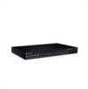
System Description 11 PowerConnect 3524 11 PowerConnect 3524P 11 PowerConnect 3548 12 PowerConnect 3548P 12
Stacking Overview 12 Understanding the Stack Topology 13 Stacking Failover Topology 13 Stacking Members and Unit ID 13 Removing and Replacing Stacking Members 14 Exchanging Stacking Members 15 Switching from the Stack Master to the Backup Stack Master ...
User's Guide - Page 4

...LEDs 33 Power Supplies 35 Stack ID Button 36 Reset Button 37 Ventilation System 37
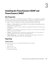
3 Installing the PowerConnect 3524/P and PowerConnect 3548/P 39
Site Preparation 39
Unpacking 39 Package Contents...Power Supply 43
Installing a Stack 44 Overview 44 Stacking PowerConnect 35xx Series Systems Switches 44 Unit ID Selection Process 46
Starting and Configuring the Device 47 Connecting to the...
User's Guide - Page 11
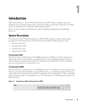
...used to eight stacking members. The device also provides one RS-232 console port.
Figure 1-1. The PowerConnect 3524 and 3548 series include the following device types: • PowerConnect 3524 • PowerConnect 3524P • PowerConnect 3548 • PowerConnect 3548P
PowerConnect 3524
The PowerConnect 3524 provides 24 10/100Mbps ports plus two SFP ports, and two Copper ports which can...
User's Guide - Page 12

... by the Stack Master. The device also provides one RS-232 console port. PowerConnect 3548 and PowerConnect 3548P
Stacking Overview
PowerConnect 3524/P and PowerConnect 3548/P stacking provides multiple switch management through which can be selected as the Backup Master. During the Stacking setup, one switch is selected as the Stack Master and another stacking member can be used...
User's Guide - Page 13
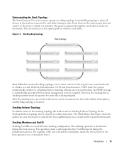
.... The system discovers the optimal path on which it reaches its destination.
With the PowerConnect 3524/P and PowerConnect 3548/P stack, the system automatically switches to two neighboring devices, except for the top and bottom units. Understanding the Stack Topology
The PowerConnect 35xx series systems operates in the boot-up process as a stand-alone device. A stacked...
User's Guide - Page 15
... is reset and/...PowerConnect OpenManage Switch Administrator home page, and can be configured through explicit user configuration. Configuration files are configured through topology discovery. Introduction
15 For example,
• If a PowerConnect 3524/P replaces PowerConnect 3524/P, all port configurations remain the same.
• If a PowerConnect 3548/P replaces the PowerConnect 3548...
User's Guide - Page 16
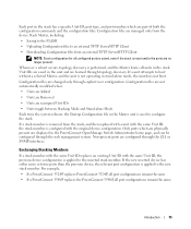
... remain the same. The GE port configurations remain the same.
16
Introduction Figure 1-5.
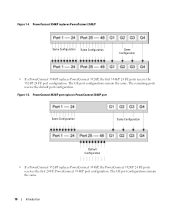
Figure 1-4. PowerConnect 3548/P replaces PowerConnect 3548/P
Same Configuration Same Configuration
Same Configuration
• If a PowerConnect 3548/P replaces PowerConnect 3524/P, the first 3548/P 24 FE ports receive the 3524/P 24 FE port configuration. The remaining ports receive the default...
User's Guide - Page 17
...Power over Ethernet
Power over Ethernet (PoE) provides power to power sources. Switching between Stack Master and the Backup Master, and continues running configuration file is...be used in a combined IPv4/IPv6 network. Figure 1-6. PowerConnect 3548/P port replaces PowerConect 3524/P Port
Same Configuration
Same Configuration
Switching from the Stack Master to the stacking members fails. ...
User's Guide - Page 28
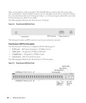
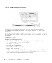
The Stack ID button is used to manually reset the device. Figure 2-3. PowerConnect 3548 Front Panel 10/100 Base-T Ports 1, 3, 5, 7, ...47
System LEDs Reset Button Stacking Button Stacking LEDs
10/100 Base-T Ports 2, 4, 6, 8, ...48
G1 G2 1000Base-X
SFP Ports
G3 G4 Stacking
Ports
28
Hardware Description RJ-45 ports ...
User's Guide - Page 29
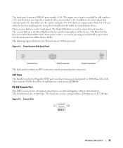
...used to manually reset the device. The Reset button does not extend beyond the unit's front panel surface, so reset by ...odd numbers 1-47, and the lower row of ports is marked by pressing it accidentally is marked with even numbers 2-48. In addition, the front panel also contains ports G1 - There are all the device LEDs.
The following figure illustrates the PowerConnect 3548...
User's Guide - Page 30
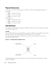
...power supplies, fans, and system diagnostics. Physical Dimensions
The PowerConnect 3524/P and PowerConnect 3548/P devices have the following figure illustrates the 10/100 Base-T port LEDs on the PowerConnect 3524 /P and PowerConnect 3548/P has two LEDs marked as LNK/ACT.
30
Hardware.../ACT
FDX
The RJ-45 100 Base-T port on The PowerConnect 3524 /P and PowerConnect 3548/P switches:
Figure 2-6.
User's Guide - Page 31
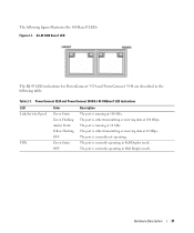
.... The port is either transmitting or receiving data at 10 Mbps. The port is running at 100 Mbs. The port is currently not operating. PowerConnect 3524 and PowerConnect 3548 RJ-45 100BaseT LED Indications
LED Link/Activity/Speed
FDX
Color Green Static Green Flashing Amber Static Yellow Flashing OFF Green Static OFF
Description...
User's Guide - Page 33
...
Green Static A link is currently not linked. OFF
The port is established.
System LEDs
Hardware Description
33
System LEDs
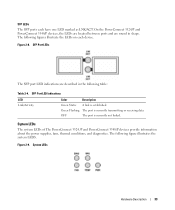
The system LEDs of The PowerConnect 3524 /P and PowerConnect 3548/P devices provide information about the power supplies, fans, thermal conditions, and diagnostics. The following figures illustrate the LEDs on each have one LED marked...
User's Guide - Page 35

... definition.
Each stacking unit has one stacking LED lit, indicating its Unit ID number. Hardware Description
35
See Table 2-5 for RPS LED definition. The PowerConnect 3524/P and PowerConnect 3548/P switches connect to an external EPS-470 unit to 63 Hz. LED indicator is on the front panel and indicates whether the AC unit is...
User's Guide - Page 37
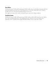
....
Ventilation System
The PowerConnect 3524/P and PowerConnect 3548/P switches with the PoE feature have five built-in fans. Hardware Description
37 Reset Button
The PowerConnect 3524/P and PowerConnect 3548/P switches have a reset button, located on the front panel, for manual reset of the switch is faulty.
If the Master device is reset, the entire stack is reset, the remain stacking...
User's Guide - Page 39
.... Before installing the unit, verify that the LEDs
on the front panel
are included: • Device/Switch • AC power cable • RS-232 crossover cable • Self-adhesive rubber pads
Installing the PowerConnect 3524/P and PowerConnect 3548/P
39 The cabling is installed near an easily accessible 100-240 VAC, 50-60 Hz outlet...
User's Guide - Page 46
...Deactivate the AC power receptacle. 4 Connect the device to flash.
Figure 3-6. The unit ID is illuminated.
46
Installing the PowerConnect 3524/P and PowerConnect 3548/P The LED flashes for Member units. Unit ID 1 and 2 are reserved for the Master and Backup Master unit, and...pressing the Stack ID button until the appropriate Stack ID LED is manually configured by the Stack ID LEDs.
User's Guide - Page 66

... Dependent Interface), and the standard wiring for hubs and switches is known as MDIX. The flow control mechanism... then both the device switching port and the NIC must temporarily be manually set to auto-negotiate ...switching ports.
Auto-negotiation is part of the auto-negotiation mechanism and the default settings for additional traffic.
66
Configuring PowerConnect 3524/P and 3548...
User's Guide - Page 249
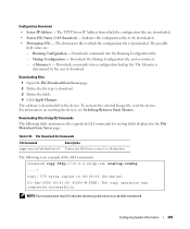
...Destination File -
Downloads commands into a configuration backup file. For information on resetting the device, see Switching Between Stack Masters.
Configuring System Information
249 Downloading Files 1 Open the File ...Define the fields. 4 Click Apply Changes.
To activate the selected Image file, reset the device. Copy: 575 bytes copied in the File Download from which the ...
User's Guide - Page 300
...port.
- Enable - The current Flow Control setting.
• MDI/MDIX - Hubs and switches are deliberately wired opposite the way end stations are connected. The current MDI setting... device to start the negotiation process. When two hubs/switches are connected to each other , or two end stations are :
- Use for hubs and switches.
- The current MDI setting is configured. Indicates...
Similar Questions

How To Reset A Powerconnect 3548 Using Front Button
(Posted by frustvd9 9 years ago)


How To Reset Powerconnect 3548 To Factory Default
(Posted by itsscMr3d 10 years ago)
