
Dell OptiPlex 755 Support Question
Dell OptiPlex 755 Support Question
Find answers below for this question about Dell OptiPlex 755.Need a Dell OptiPlex 755 manual? We have 3 online manuals for this item!
Question posted by Shoaimar on July 5th, 2014
What Devices Must Be Removed Prior To Removed The System Board On The Optiplex
580 minitower (mt) desktop
Current Answers
Related Dell OptiPlex 755 Manual Pages
Quick Reference
Guide - Page 3
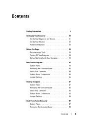
... Inside Your Computer 14
Mini Tower Computer 16 System Views 16 Removing the Computer Cover 22 Inside Your Computer 24 System Board Components 25 Jumper Settings 26
Desktop Computer 27 System Views 27 Removing the Computer Cover 32 Inside Your Computer 33 System Board Components 35 Jumper Settings 36
Small Form Factor Computer 37 System...
Quick Reference
Guide - Page 6
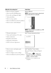
... information • End User License Agreement
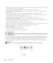
NOTE: This document is available as a PDF at support.dell.com. Dell™ Product Information Guide
• How to remove and replace parts
Dell™ OptiPlex™ User's Guide
• Specifications
Microsoft Windows Help and Support
• How to configure system settings
Center
• How to...
Quick Reference
Guide - Page 14
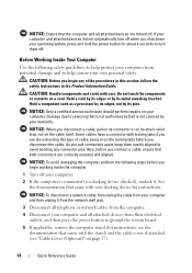
... device for instructions. Damage due to servicing that the computer and all attached devices from their electrical outlets, and then press the power button to ground the system board.
5 If applicable, remove ... To disconnect a network cable, first unplug the cable from your computer and attached devices did not automatically turn them evenly aligned to avoid bending any of the procedures in ...
Quick Reference
Guide - Page 65
...).
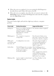
On the desktop computer, a ... device on the keyboard to
board ...may indicate a computer problem.
incorrectly installed.
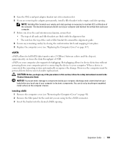
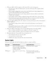
Power Light
Problem Description
Suggested Resolution
Solid green
Power is in the
failure has occurred. Quick Reference Guide
65 4 When the tests are completed, if you are running the Dell Diagnostics from the Drivers and Utilities CD, remove...
User's Guide - Page 9
...234 Resetting the Chassis Intrusion Detector 235
System Board Components 236 Cable Cover (Optional 237 Attaching the Cable Cover 237 Removing the Cable Cover 237
Connecting the AC ...252
Module Bay 255 Installing a Device When Your Computer Is Turned Off 255 Removing and Installing a Device When Your Computer Is Running Microsoft® Windows 258 Securing a Device in the Module Bay 259
...
User's Guide - Page 12
... 303
11 Replacing the System Board
Removing the System Board: Mini Tower, Desktop, Small Form Factor, and Ultra Small Form Factor Computers 307
Mini Tower System Board Screws 308 Desktop System Board Screws 309 Small Form Factor System Board Screws 310 Ultra Small Form Factor System Board Screws 311 Replacing the System Board: Mini Tower, Desktop, Small Form Factor, and Ultra...
User's Guide - Page 22
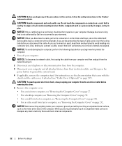
... your computer and all attached devices from the electrical outlet before ... removing the cover.
5 Remove the computer cover.
• For a mini tower computer, see "Removing the Computer Cover" on page 27.
• For a desktop computer, see "Removing ... system board.
4 If applicable, remove the computer stand (for instructions, see "Removing the Computer Cover" on page 237...
User's Guide - Page 51
... on the computer chassis.
1 Remove the computer cover (see "Removing the Computer Cover" on your computer.
Hot-plugging allows for device detection without powering down before you...Product Information Guide. However, the computer must be powered down your computer prior to connecting the device to components inside your computer, discharge static electricity from your computer's electronic...
User's Guide - Page 113
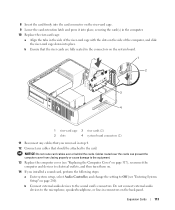
...the Computer Cover" on page 317), reconnect the computer and devices to electrical outlets, and then turn them on.
14 If you removed in step 4.
12 Connect any cables that should be ...the side of the riser-card cage with the slots on the system board.
1
2
3 4
1 riser-card cage 3 riser cards (2)
2 slots
4 system board connectors (2)
11 Reconnect any cables that you installed a sound card, ...
User's Guide - Page 115
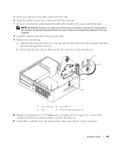
... in the connectors on the system board.
1
2
3
4
1 riser-card cage 3 riser cards (2)
2 slots
4 system board connectors (2)
10 Replace the computer cover (see "Replacing the Computer Cover" on page 317), reconnect the computer and devices to maintain FCC certification of the computer.
b Ensure that the riser cards are removing the card permanently, install a filler bracket...
User's Guide - Page 123
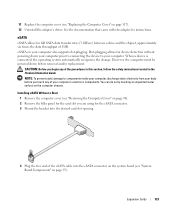
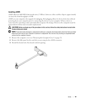
...prior to connecting the device to components inside your computer, discharge static electricity from your computer's electronic components. You can do so by touching an unpainted metal surface on page 90). 2 Remove the filler panel for the card slot you touch any of your body before removal...eSATA cable into the eSATA connector on the system board (see "Replacing the Computer Cover" on page...
User's Guide - Page 184
...the Onboard Devices group, and change the setting to Off (see "System Setup" on page 168). NOTE: For PCI card locations, see "Removing the Computer Cover" on page 280).
Removing a ...any drivers required for the card as described in "Before You Begin" on page 21. 2 Remove the computer cover (see "System Board Components" on page 172. 3 Gently lift the release tab on the back panel of its ...
User's Guide - Page 193
... follow the safety instructions located in the empty card-slot opening . When a device is necessary to maintain FCC certification of the computer.
You can do so by...down your computer prior to connecting the device to components inside your computer, discharge static electricity from your body before removal and/or replacement.
Hot-plugging allows for device detection without powering ...
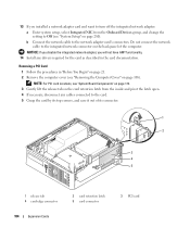
User's Guide - Page 258
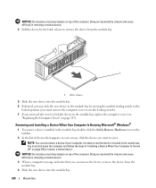
... moving the module locking switch to the
locked position (you must shut down the computer and follow the steps in removing a module device.
4 Pull the device by the latch release to remove a locked device. NOTE: You cannot remove a device if your screen, click the device you can remove the device, remove the device from the module bay.
1
1 latch release
5 Slide the new...
User's Guide - Page 291
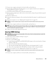
...2 Remove the computer cover. 3 Reset the current CMOS settings: a Locate the password (PSWD) and CMOS (RTC_RST) jumpers on the system board (... it into the computer. 12 Connect your computer and devices to electrical outlets, and turn them on.
Advanced Features... turn them on. 6 After the Microsoft® Windows® desktop appears on your computer, shut down your computer (see
"Turning Off...
User's Guide - Page 332
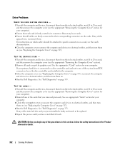
... off the computer and devices, disconnect them from their electrical outlets, wait 10 to 20 seconds, and then remove the computer cover (see the appropriate "Removing the Computer Cover" section for your computer). 2 Reinstall one of the procedures in this process until you begin any of the system board IDE connectors, leave the drive...
User's Guide - Page 340
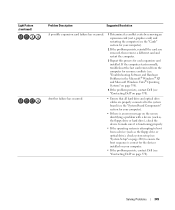
... self-test feature can be malfunctioning or incorrectly installed. • Ensure that the processor power cable is securely connected to the system board power connector (POWER2) (see
the "System Board Components" section for your computer). • Remove and then reinstall all components and cables are properly installed and securely connected to the system...
User's Guide - Page 345
...the desktop
computer, a solid green light indicates
a network connection. Remove and then reinstall the memory modules (see the "Cards" section for your location, if applicable. - Too many devices on...strip is turned on the back of interference are securely connected to the system board (see the "System Board Components" section for your computer).
• If the power light is ...
User's Guide - Page 346
...yellow
The Dell Diagnostics is running a If the Dell Diagnostics is running, test, or a device on the system board allow the testing to see if the specific problem is identified (see "Contacting Dell" on... code and no beep code but the computer locks up during POST
An integrated system board device may be faulty or incorrectly installed.
See "Video and Monitor Problems" on diagnosing the...
User's Guide - Page 349
...board (see the "System Board Components" section for your computer).
• If there is an error message on the screen identifying a problem with a device (such as the floppy drive or hard drive), check the device... each expansion card installed. If the computer starts normally, troubleshoot the last card removed from a device (such as the floppy drive or optical drive), check system setup (see "...
Similar Questions


How To Remove Dell Optiplex 3010mt Service Panel
(Posted by mscechoch 10 years ago)

How To Remove Hard Drive Desktop Computer Optiplex 755
(Posted by anlo 10 years ago)
