Dell OptiPlex 745 Support Question
Dell OptiPlex 745 Support Question
Find answers below for this question about Dell OptiPlex 745.Need a Dell OptiPlex 745 manual? We have 1 online manual for this item!
Question posted by stacysag on February 17th, 2014
Optiplex Gx745 How To Remove Front Panel
The person who posted this question about this Dell product did not include a detailed explanation. Please use the "Request More Information" button to the right if more details would help you to answer this question.
Current Answers
Related Dell OptiPlex 745 Manual Pages
Quick Reference
Guide - Page 2

... written permission of your computer.
If you purchased a Dell™ n Series computer, any references in this text: Dell, the DELL logo, Inspiron, Dell Precision, Dimension, OptiPlex, Latitude, PowerEdge, PowerVault, PowerApp, and Dell OpenManage are registered trademarks of Microsoft Corporation. All rights reserved. Reproduction in any proprietary interest in this document is...
Quick Reference
Guide - Page 3
... - Front View 17 Small Form Factor Computer - Back View 10 Mini Tower Computer - Back-Panel Connectors 19 Ultra-Small Form Factor Computer - Back-Panel Connectors 23
Removing the Computer Cover 24 Before You Begin 25 Mini Tower Computer 26 Desktop Computer 27 Small Form Factor Computer 28 Ultra-Small Form Factor Computer 30
Inside...
Quick Reference
Guide - Page 5
...my computer • My computer documentation • My device documentation • Desktop System Software (DSS)
• How to remove and replace parts • Specifications • How to configure system settings ... drivers are already installed on the optional Drivers and Utilities CD. Dell™ OptiPlex™ User's Guide
Microsoft Windows XP Help and Support Center 1 Click Start&#...
Quick Reference
Guide - Page 11
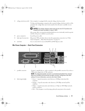
...8226; Off - A good connection exists between a 100-Mbps network and the computer.
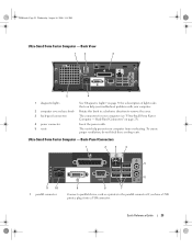
• Yellow - Back-Panel Connectors
1
2 34
5
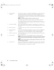
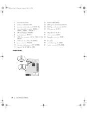
9 1 parallel connector
2 link integrity light
6
8
7
Connect a parallel device, ...switch, set to the network. For more information, see "Mini Tower Computer - Back-Panel Connectors" on page 11).
6 card slots
Access connectors for the voltage that your ...
Quick Reference
Guide - Page 12
...
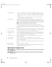
6 line-in/microphone connector
Use the blue and pink line-in a steady "on the card. Do not remove the cap. For more information, see your network. NOTE: Do not plug a telephone cable into a sound ...as a cassette player, CD player, or VCR.; Connect your monitor to the connector on the back panel of your network or broadband device. book.book Page 12 Wednesday, August 16, 2006 3:18 PM...
Quick Reference
Guide - Page 15
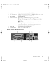
...: The voltage selection switch must be set the switch for any installed PCI and PCI Express cards.
2 back-panel connectors
Plug serial, USB, and other devices into the appropriate connectors (see "Desktop Computer -
Back-Panel Connectors" on page 15).
3 power connector
Insert the power cable.
4 voltage selection switch Your computer is 100 V. book...
Quick Reference
Guide - Page 16
... when the computer is recommended that supports dual monitors, use the connector on the back panel of network traffic may make this connector will be in /microphone connector to the parallel connector... serial connector 1 and COM2 for devices that the network cable has been securely attached.
Do not remove the cap. NOTE: If you have a USB printer, plug it into a sound or telephony...
Quick Reference
Guide - Page 19

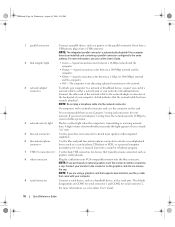
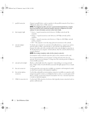
...you to the 115-V position even though the AC power available in your location. Back-Panel Connectors" on page 19).
3 power connector
Insert the power cable.
4 voltage selection ... open the computer cover.
To help avoid damaging a computer with a manual voltage-selection switch.
Back-Panel Connectors
1
2 34
9
8
5
6 7
Quick Reference Guide
19 NOTICE: The voltage selection switch...
Quick Reference
Guide - Page 20
... the computer.
• Off - A good connection exists between a 10-Mbps network and the computer.
• Orange -
If you must use the connector on the back panel of your online User's Guide.
2 link integrity light
• Green - NOTE: Do not plug a telephone cable into a sound or telephony program.
7 USB 2.0 connectors (6) Use the...
Quick Reference
Guide - Page 23
... that can help prevent your computer (see "Ultra-Small Form Factor Computer - Back-Panel Connectors" on page 50 for your computer from overheating.
Back-Panel Connectors
1
2
3
4
5
6
11 10 1 parallel connector
9
8
7
Connect a parallel device, such as a printer, to remove the cover. Quick Reference Guide
23 Back View
1
2
3
5
4
1 diagnostic lights
2 computer cover release...
Quick Reference
Guide - Page 24
... a network jack or your computer from your monitor into the white connector on the back panel of the procedures in a steady "on the card.
A good connection exists between a 10...- A good connection exists between a 1000-Mbps (1-Gbps) network and the
computer. • Off - Removing the Computer Cover
CAUTION: Before you use the connector on " state. It is recommended that can help...
Quick Reference
Guide - Page 25
...edges, not by its strain-relief loop, not on your computer from the electrical outlet before removing the cover. To avoid damaging the computer, perform the following safety guidelines to help protect your...outlets, and then press the
power button to ground the system board. 4 If applicable, remove the computer stand (for instructions, see the documentation that is not authorized by Dell is ...
Quick Reference
Guide - Page 26
... page 30). book.book Page 26 Wednesday, August 16, 2006 3:18 PM
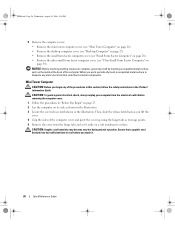
5 Remove the computer cover: • Remove the mini tower computer cover (see "Mini Tower Computer" on page 26). • Remove the desktop computer cover (see "Desktop Computer" on page 27). • Remove the small form factor computer cover (see "Small Form Factor Computer" on...
Quick Reference
Guide - Page 27
..., August 16, 2006 3:18 PM
1 2 3
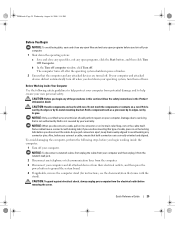
1 security cable slot
2 cover release latch
3 padlock ring
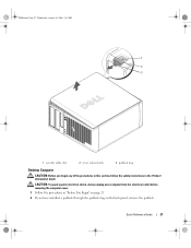
Desktop Computer
CAUTION: Before you begin any of the procedures in this section, follow the safety instructions in "Before You Begin" on page 25. 2 If you have installed a padlock through the padlock ring on the back panel, remove the padlock.
Quick Reference
Guide - Page 28
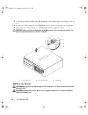
...soft nonabrasive surface. Ensure that a graphic card heatsink has had sufficient time to cool before removing the computer cover.
28
Quick Reference Guide CAUTION: Graphic card heatsinks may become very hot ...during normal operation. Then, slide the release latch back as leverage points. 5 Remove the cover from the electrical outlet before you lift the cover.
4 Grip the sides of ...
Quick Reference
Guide - Page 29
....
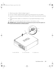
4 Grip the sides of the computer cover and pivot the cover up using the bottom hinges as leverage points.
5 Remove the cover from the hinge tabs and set it aside on the back panel, remove the padlock.
3 Locate the cover release latch shown in "Before You Begin" on page 25.
2 If you touch...
Quick Reference
Guide - Page 30
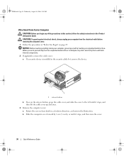
... NOTICE: Before touching anything inside your computer from the electrical outlet before removing the computer cover. 1 Follow the procedures in the illustration. While you begin any static electricity that... surface to the left until it stops, and then lift the cable cover up and away.
3 Remove the computer cover: a Rotate the cover release knob in a clockwise direction, as shown in "Before...
Quick Reference
Guide - Page 34
... (RTCRST)
16 PCI connector (SLOT3)
6 password jumper (PSWD)
17 serial connector (SER2)
7 SATA drive connectors (SATA0, SATA1, SATA4, 18 floppy drive connector (DSKT) SATA5)
8 front-panel connector (FNT_PANEL)
19 flea power
9 power connector (POWER)
20 system board speaker (BEEP)
10 intrusion switch connector (INTRUDER)
21 speaker connector (INT_SPKR)
11 internal USB...
Quick Reference
Guide - Page 35
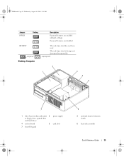
... drive bays (media card reader 2 or floppy drive, optical drive and hard drive)
4 system board
5
7 front I/O panel
power supply card slots
6
3 optional chassis-intrusion switch
6 heat sink assembly
Quick Reference Guide
35 Password features are enabled .... The real-time clock is being reset (jumpered temporarily). RTCRST
jumpered
Desktop Computer
The real-time clock has not been reset.
Quick Reference
Guide - Page 58
... Page 58 Wednesday, August 16, 2006 3:18 PM
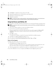
18 Click Finish to complete the setup, and remove the CD. 19 Reinstall the appropriate drivers with the Drivers and Utilities CD. 20 Reinstall your virus ...while you are running Windows.
1 Turn on the computer and allow it to boot to the Windows desktop. 2 Insert the Drivers and Utilities CD into the CD drive. To view all available drivers for your...
Similar Questions


How To Remove Panel From Dell Inspiron One 2305
(Posted by IcEmAbcmarq 10 years ago)
How To Remove Dell Optiplex 3010mt Service Panel
(Posted by mscechoch 10 years ago)