Dell Latitude CPt V Support Question
Dell Latitude CPt V Support Question
Find answers below for this question about Dell Latitude CPt V.Need a Dell Latitude CPt V manual? We have 1 online manual for this item!
Question posted by markhellard on December 24th, 2011
Floppy A: Switch To Cd Rom D: Using The Same Bay Floppy 4 Setup, Cdrom 4 System
The person who posted this question about this Dell product did not include a detailed explanation. Please use the "Request More Information" button to the right if more details would help you to answer this question.
Current Answers
Related Dell Latitude CPt V Manual Pages
Service Manual - Page 4

...trademarks and trade names other than its own. Other trademarks and trade names may be used in this document to refer to change without notice. © 1999 Dell Computer ...A00 Information in this document is strictly forbidden. All rights reserved.
Trademarks used in this text: Dell, the DELL logo, and Latitude are trademarks of Dell Computer Corporation is subject to either the entities ...
Service Manual - Page 5

... and Tightening 3 ZIF Connectors 5 Field-Replaceable Parts and Assemblies 6 Removing Field-Replaceable Parts and Assemblies 12
Hard-Disk Drive Assembly 13 Modular Bay Devices (Diskette Drive, CD-ROM Drive, DVD-ROM Drive, SuperDisk LS-120 Drive, Battery, or Travel Module 13 Memory Module Cover 14 Memory Modules 14 Keyboard Assembly 15 Microprocessor Module 19...
Service Manual - Page 6

... 6. Figure 16. Computer Orientation 1 Main Battery Assembly Removal 3 Screw Identification 3 Disconnecting an Interface Cable 5 Exploded View-Computer 12 Hard-Disk Drive Assembly Removal 13 Modular Bay Device Removal 13 Memory Module Removal 14 Removing the Keyboard Assembly Screws 16 Keyboard Assembly Removal 17 Keyboard and Track Stick Cables 18 Microprocessor Module...
Service Manual - Page 8
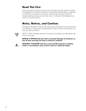
... an icon and printed in bold type or in italic type.
In addition to information provided in this manual, Dell provides the User's Guide for using the Dell Diagnostics to service Dell computer systems is a basic knowledge of PCs and prior training in PC troubleshooting techniques. Throughout this guide, blocks of...
Service Manual - Page 9
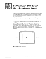
... attached peripherals are turned off, and the peripherals are as shown in your Dell Latitude portable computer. Unless otherwise noted, each procedure in this manual, the locations or ... open nearly 180 degrees, use a book or something similar to exceed 180 degrees.
back of computer
left side
right side
front of computer
support.dell.com
Dell Latitude CPt V-Series/CPx H-Series Service...
Service Manual - Page 10
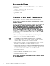
... scribe Processor extractor
Before you cannot shut down the computer using the computer's operating system, press the power button for personal injury or shock....use of one or more of the procedures in suspend-todisk mode. Also disconnect any attached peripherals from the computer.
7. If the computer is turned off the computer and any installed PC Cards.
2
Dell Latitude CPt...
Service Manual - Page 11
...support.dell.com
Dell Latitude CPt V-Series/CPx H-Series Service Manual
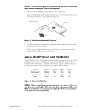
3 A graphic for correct length.
Slide the battery bay latch toward the right side of the battery bay (see Figure 2).
Remove the main battery assembly from the battery bay. Match the actual screw... correct screw length as part of the computer. The illustrations in Figure 3.
battery bay latch
battery
9. 8.
Service Manual - Page 13
....
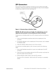
2. These connectors are zero insertion force (ZIF) connectors. Use a small flat-blade screwdriver to open the movable part of the computer's interface connectors are not removable, but they must be released to a ZIF connector, perform the following steps:
1. support.dell.com
Dell Latitude CPt V-Series/CPx H-Series Service Manual
5 movable part of connector...
Service Manual - Page 14
..., 5 CRNA
Service kit, CD-ROM drive CD-ROM drive bezel 24X CD-ROM drive CD-ROM drive interface board Bottom CD-ROM drive cover CD-ROM housing
CD-ROM drive label
SVC, SUBASSY, CD, 24X, NBK
7
BZL, CD
CD, 650M, I, INT, NBK, 24X, TSHBA
PWA, INTERCONN, CD/DVD, OMAHA
ASSY, BTM/BZL, CD, 24X, TSHBA
ASSY, HSG, PLSTC, CD/DVD, OMHA
LBL, CD, MEDIA BAY, TSHB
6
Dell Latitude CPt V-Series/CPx H-Series...
Service Manual - Page 15
... interface cable
Diskette drive assembly SHLD, FD, F3, CRNA shield
LS-120 drive subassembly SUBASSY, VAS, LS120, 120MB, F3 7
DVD-ROM drive subassembly
SUBASSY, DVD, 4X, MPEGII, TSH- 7 BA
Thermal cooling assembly ASSY, HTSK, COOLER, PRC
23
(includes fan)
Hard...the drive height for yy, and the manufacturer for zzz. support.dell.com
Dell Latitude CPt V-Series/CPx H-Series Service Manual
7
Service Manual - Page 20

display assembly
keyboard
palmrest assembly
hard-disk drive
system board
main battery
bottom case assembly modular bay device
The following subsections provide instructions for removing and replacing field-replaceable parts and assemblies.
12 Dell Latitude CPt V-Series/CPx H-Series Service Manual
Service Manual - Page 22

... unlock icon. Release the memory module cover. Remove the memory module cover. 14 Dell Latitude CPt V-Series/CPx H-Series Service Manual Close the display, and turn the computer over.
...memory module sockets (2)
1. Keep holding the latch open while pulling the device out of the modular bay with the other hand (see Figure 7).
1.
Insert a flat-bladed screwdriver under the indentation in the...
Service Manual - Page 28

... directly over this corner to secure the microprocessor module and shield.
20 Dell Latitude CPt V-Series/CPx H-Series Service Manual When you reinstall the microprocessor module in the... plate that secure the thermal cooling assembly arm and shield to the microprocessor module.
5. Use a microprocessor extractor tool to the corner without the mounting screw. Remove the microprocessor shield...
Service Manual - Page 31

...Remove the display assembly. 4. support.dell.com
Dell Latitude CPt V-Series/CPx H-Series Service Manual 23 Lift the LCD panel out of the top cover. Use a scribe to carefully pry the four rubber screw covers... 4-mm screws located at the top of the bezel on the front of the display assembly.
4. Use a scribe to reassemble the LCD panel in the display. Remove the main battery. 2. Remove the...
Service Manual - Page 35

... one fold to be installed. If you are installing a Torisan LCD panel, the bottom jumper is used . The manufacturer is facing up . If you are set correctly (see Figure 16). support.dell.com
Dell Latitude CPt V-Series/CPx H-Series Service Manual 27 Fold the LCD flex cable at the opposite end when compared...
Service Manual - Page 38

Remove the main battery. 2. Remove the device from the modular bay. 3. Turn the computer upside down on the work surface. 6. Remove the display assembly. 5. Remove the five ... edge of the computer (see Figure 18). 7. Turn the computer right-side up on a flat work surface.
30 Dell Latitude CPt V-Series/CPx H-Series Service Manual
Remove the keyboard. 4. 20-mm screws (5)
M2.5x20
1.
Service Manual - Page 39

.... 4. Carefully remove the palmrest assembly from the touch-pad connector on the system board (see Figure 19).
1. Remove the display assembly. 5. support.dell.com
Dell Latitude CPt V-Series/CPx H-Series Service Manual 31
Remove the palmrest assembly. 8. Remove the device from the modular...
Service Manual - Page 41

...7. Remove the main battery. 2. If the module latch assembly does come loose from the modular bay. 3. Remove the palmrest assembly. 6. Carefully reinsert the spring onto the slider on the module ... through 8 for the system board assembly includes a
support.dell.com
Dell Latitude CPt V-Series/CPx H-Series Service Manual 33 Remove the keyboard assembly. 4. The replacement kit for the latch ...
Service Manual - Page 42

...Remove the keyboard assembly. 4. Remove any PC Cards or plastic blanks from the modular bay. 3. Remove the main battery. 2. diskette that provides a utility for the white ...and to the replacement system board assembly.
1. Verify that outline the captive washers.
34 Dell Latitude CPt V-Series/CPx H-Series Service Manual Remove the display assembly. 5. Remove the palmrest assembly. 6. ...
Service Manual - Page 45

... inverter removal, 26 replacement, 27
14.1-inch LCD display panel removal, 23
14.1-inch LCD flex cable removal, 24
battery (in modular bay) removal, 13
battery (reserve) removal, 31
CD-ROM drive removal, 13
computer exploded view, 12 working inside, 2
diskette drive removal, 13
display assembly bezel, removal, 22 removal, 21
display assembly...
Similar Questions

How To Boot From Cd Rom In Dell Inspirion N4010
(Posted by coco3foxkat 9 years ago)


How To Use The Fingerprint Scanner On My Dell Laptop Latitude E6520
(Posted by DOzomb 10 years ago)

Cd Rom How Do I Get It To Work On My Notebook Step By Step
(Posted by albertagriego 11 years ago)
My Laptop Is Running Hot With Loud Fan On All The Time.
Where is the microprocessor located in the D430 latitude laptop? My device is running hot in the rig...
Where is the microprocessor located in the D430 latitude laptop? My device is running hot in the rig...
(Posted by adamseiver 12 years ago)