Biostar P4M900-M7 FE Support Question
Biostar P4M900-M7 FE Support Question
Find answers below for this question about Biostar P4M900-M7 FE.Need a Biostar P4M900-M7 FE manual? We have 1 online manual for this item!
Question posted by djezekiel98 on July 3rd, 2012
Were Is Power Connector?
The person who posted this question about this Biostar product did not include a detailed explanation. Please use the "Request More Information" button to the right if more details would help you to answer this question.
Current Answers
Related Biostar P4M900-M7 FE Manual Pages
Setup Manual - Page 1
... with the limits of a Class B digital devic e, purs uant to Part 15 of the FCC Rules .T hese limits are trademarks of their respec tive companies .
P4M900-M7 FE Setup Manual
FCC Information and Copyright
This equipment has been tes ted and found in this publication and to make c hanges to the c ontents here...
Setup Manual - Page 2
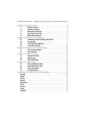
Table of Contents
Chapter 1: Introduction 3
1.1
Before You Start 3
1.2
Package Checklist 3
1.3
Motherboard Features 4
1.4
Rear Panel Connectors 5
1.5
Motherboard Layout 6
Chapter 2: Hardware Installation 7
2.1
Installing Central Processing Unit (CPU 7
2.2
Fan Headers 9
2.3
Installing System Memory 10
2.4
Connectors and Slots 12
Chapter 3: Headers & Jumpers Setup 14...
Setup Manual - Page 3
....
„ Avoid touching the compone nts on mothe rboard or the rear side of the board unless ne cessary. P4M900-M7 FE
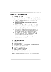
CHAPTER 1: INTRODUCTION 1.1 BEFORE YOU START
Thank you for ATX Case X 1 FDD Cable X 1 (optional) Se ... ct the compute r from anti-static bag, ground yourse lf prope rly by area or your motherboard version.
3 Be fore you start installing the mo the rboa rd, plea se make sure you...
Setup Manual - Page 4
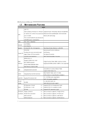
...connector
x1 Each connector supports 2 Flo ppy drives
Connector Printer Port C onnector
x1 Each connector supports 1 Pri nter port
IDE Co nnector
x2 Each connector supports 2 IDE device
SATA Connector
x2 Each connector... MHz
Chipset Graphic
VIA P4M900 VIA VT8237A Chrome9 HC 3D / 2D Graphics
Max Share d Vide o Memory is recommende d to 1.5 Gb/s.
Motherboard Manual
1.3 MOT HERBOARD ...
Setup Manual - Page 5
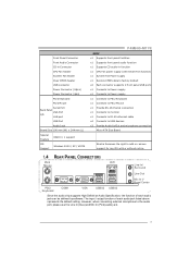
... Feature
RAID 0 / 1 support
OS Support
Windows 2000 / XP / VISTA
P4M900-M7 FE
SPEC x1 Supports front panel facilities x1 Supports front panel a udio function x1 Supports CD audio-in Co nnector
CPU Fan hea der
System Fan hea der
Clear CMOS header
USB connector
Power Connector ( 24pi n)
Power Connector ( 4pin)
PS/2 Keyboard
PS/2 Mo use x1 Provide RS...
Setup Manual - Page 6
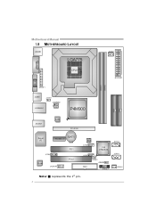
Motherboard Manual
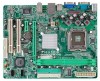
1.5 MOT HERBOARD LAYOUT
JKB MS1
LGA775
JCFAN1
COJMC1OM1
CPU1
JATXPWR1
JVGA1
DIMM1 DIMM2
JPRNT1
JUSB1
JUSBV1 JATXPWR2
J US BLAN1
P4M900
IDE1 IDE2
JAUDIO1
LAN
PCI-E X16
Super I/O
BAT1
PCI-EX1_1
JCDIN1
Codec
JAUDIOF1
PCI1 PCI2
BIOS JU SB2
VIA VT8237A
JUSB3 FDD1
JUSBV2 JCMOS1
JPAN EL 1
JSATA2 JSATA1
JSFAN1
Not e: ■ represe nts the 1st pin.
6
Setup Manual - Page 7
P4M900-M7 FE
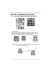
CHAPTER 2: HARDWARE INSTALLATION 2.1 INST ALLING CENT RAL PROCESSING UNIT (CPU)
Special Notice: Remove Pin Cap before installation, and make good preservation for future use. Pin ...
Setup Manual - Page 8
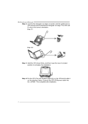
...assembly on the CPU and buckle it on CPU should point forwards this triangular cut edge. Connect the CPU FAN power cable into the JCFAN1. This completes the installation.
8 Step 2-1:
Step 2-2:
Step 3: Hold the CPU down...installation. The CPU will fit only in the correct orientation. Motherboard Manual Step 2: Look for the triangular cut edge on socket, and the golden dot on the retention frame.
Setup Manual - Page 9
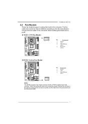
... RPM rate
sense
4
Smart Fan
Control
JSFAN1: System Fan He ader
Pin Assignment
1
Ground
2
+12V
3
FAN RPM rate
sense
3 1
Note: The JSFAN1 supports 3-pin head connector and the JCFAN1 supports 4-pin head connector.
P4M900-M7 FE
2.2 FAN HEADERS
These fan headers support cooling-fans built in the computer. When connecti ng with wires onto...
Setup Manual - Page 11
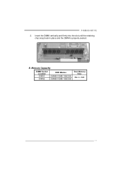
Insert the DIMM vertically and firmly into the slot until the retaining chip snap back in place and the DIMM is 4GB.
11 B. P4M900-M7 FE
2. Memory Capacity
DIMM Socket Location DIMM1
DIMM2
DDR Module
256MB/512MB/1GB/2GB 256MB/512MB/1GB/2GB
Total Memory Size
Max is properly seated.
Setup Manual - Page 12
... floppy disk ty pes. The f irst hard drive should always be connected to four hard disk drives. Motherboard Manual
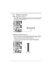
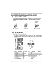
2.4 CONNECT ORS AND SLOT S
FDD1: Floppy Disk Conne ctor
The motherboard prov ides a standard floppy disk connector that prov ides PIO Mode 0~4, Bus Master, and Ultra DMA 33/66/100/133 f unctionality. It has...
Setup Manual - Page 13
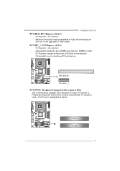
... the traditional PCI architecture. PCI-EX 16
PCI-EX 1_1 PCI1/PCI2: Pe riphe ral Component Inte rconne ct Slots
This motherboard is a bus standard for expansion cards. PCI stands f or Peripheral Component Interconnect, and it is equipped with 2 standard ... raw bit-rate of 8GB/s totally. PCI-Express 1.0a compliant. -
PCI-Express 1.0a compliant. - P4M900-M7 FE PCI-EX16: PCI-Express x16 Slot -
Setup Manual - Page 14
... Heade r
This 16-pin connector includes Power-on pins, the jumper is "close", if not, that means the jumper is placed on , Reset, HDD LED, Power LED, and speaker connection.
...15 16
Assignment N/A N/A N/A Power LED (+) Power LED (+) Power LED (-) Power button Ground
Functio n N/A N/A Power LED
Power-on button
14 It allows user to set up jumpers. Motherboard Manual
CHAPTER 3: HEADERS & ...
Setup Manual - Page 15
...
1
+12V
2
+12V
2
3
3
Ground
4
Ground
15 P4M900-M7 FE
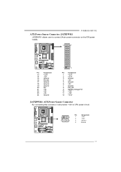
ATX Powe r Source Conne ctor: JATXPWR1
JATXPWR1 allows user to connect 24-pin power connector on the ATX power supply.
12
24
Pin
Assignment
13
+3.3V
14
-12V
15
Ground...StandbyVoltage+5V 10 +12V 11 +12V 12 +3.3V
JATXPWR2: ATX Powe r Source C onne ctor
By connecting this connector, it will provide +12V to CPU power circuit.
Setup Manual - Page 16
... connector; Motherboard Manual
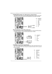
JUSB2/JUSB3: Heade rs for USB 2.0 Ports at Front Panel
This header allows user to connect the front audio output cable with the PC f ront panel. AC'97 connector... Ground
2 10 JUSB2 9 Key
10 NC
1 9 JUSB3
JSATA1/JSATA2: Se rial ATA Conne ctors
The motherboard has a PCI to SATA Controller with 2 channels SATA interf ace, it satisfies the SATA 1.0 spec and with internal...
Setup Manual - Page 17
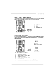
... 2-3 close ". 5. Set the jumper to "Pin 1-2 close ". 3. Power on pin2-3, it allows user to restore the BIOS saf e setting and ...r
By placing the jumper on the AC. 6. Wait f or f ive seconds. 4. P4M900-M7 FE
JCDIN1: CD-RO M Audio-in Connector
This connector allows user to avoid damaging the motherboard.
13
Pin 1-2 Close: Normal Operation (default).
13
13
Pin 2-3 Close: Clear CMOS ...
Setup Manual - Page 19

... viduall y.
19 JUSBV2: +5V for USB ports at f ront panel (JUSB2/JUSB3).
P4M900-M7 FE
JUSBV1/JUSBV2: Powe r Source Heade rs for USB Ports
Pin 1-2 Close: JUSBV1: +5V for USB ports at JUSB1/JUSBLAN1.
JUSBV2: USB ports at JUSB1/JUSBLAN1 are powered by +5V standby v oltage. Pin 2-3 Close: JUSBV1: USB ports at front panel...
Setup Manual - Page 21

... applied for the storage space of data if the active volume or drive is impaired during driv e rebuilds. Fault Tolerance: Yes. Should one driv e. P4M900-M7 FE
RAID 1:
Every read and write is actually carried out in parallel across 2 disk drives in the array. Perf ormance is corrupted or becomes unavailable because...
Setup Manual - Page 23
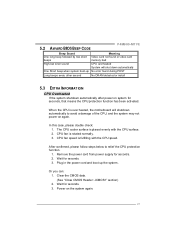
... shutdown automatically after power on system for seconds. 3. Wait for seconds, that means the CPU protection function has been activated. CPU fan is over heated, the motherboard will shut down ...may not power on the system again.
23 When the CPU is rotated normally. 3. The CPU cooler surface is fulfilling with the CPU surface. 2.
5.2 AWARD BIOS BEEP CODE
P4M900-M7 FE
Beep Sound ...
Setup Manual - Page 25

P4M900-M7 FE This page is intentionally left blank.
25
Similar Questions

Como Actualizar La Bios De P4m900-m7 Fe
Que debo hacer para correr la actualización de la bios
Que debo hacer para correr la actualización de la bios
(Posted by jizrmazz 3 years ago)

About P4m900 M7 Fe Ver.1.0
i have P4M900 M7 FE Ver.1.0 motherboard..Can i replace dual core processor in this motherboard?
i have P4M900 M7 FE Ver.1.0 motherboard..Can i replace dual core processor in this motherboard?
(Posted by albertrama13 10 years ago)

8gb Ram On Motherboard G31 M7 V 6.5 Te
is there any way I can instal 8GB RAM on motherboard G31 M7 v 6.5 TE?
is there any way I can instal 8GB RAM on motherboard G31 M7 v 6.5 TE?
(Posted by placewithspace 10 years ago)

How Can I Get The Sound Card Driver For This P4m900-m7 Fe, May I Have It?
I lost Dis setup for P4M900-M7 FE for window XP. I can not hear or play video, so that my computer s...
I lost Dis setup for P4M900-M7 FE for window XP. I can not hear or play video, so that my computer s...
(Posted by saroeuno 11 years ago)
Hook Up Power Connectors
where do the power t amd power i hook up on a biostar ta 990fxe?
where do the power t amd power i hook up on a biostar ta 990fxe?
(Posted by tombraider1961 11 years ago)