
AIWA CDC-X227 Support Question
AIWA CDC-X227 Support Question
Find answers below for this question about AIWA CDC-X227.Need a AIWA CDC-X227 manual? We have 2 online manuals for this item!
Question posted by mcneall32 on April 7th, 2021
Need To Know The Wiring Details For Each Pin On The Back
The person who posted this question about this AIWA product did not include a detailed explanation. Please use the "Request More Information" button to the right if more details would help you to answer this question.
Current Answers
Answer #1: Posted by Vktech1 on April 8th, 2021 10:24 AM
Vktech1

Member since:
March 4th, 2021 Points: 106,910

Member since:
March 4th, 2021 Points: 106,910
Use the link below to get an manuals
http://caraudio.manualsonline.com/manuals/mfg/aiwa/cdcx227.html
Vasanth
Related AIWA CDC-X227 Manual Pages
Operating Instructions - Page 2
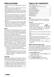
... use a CD-R or CD-RW that contains no guarantee that pins or other computer files. To cancel DEMO mode 1 During DEMO ...in the display. 2 Press i or k to select "DE". 3 Turn AUDIO CONTROL to select "DE 0." Laser beams from the center outward with the ...not expressly approved by one with an identical amperage rating. For detailed descriptions, refer to the related pages. CD Notes •...
Operating Instructions - Page 6
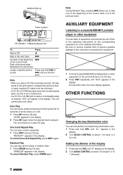
...10 seconds of the display 1 Press and hold SEL until "AUX" appears in the display. 2 Turn AUDIO CONTROL to select "D 0 (bright)" or "D
1 (dimmed)."
5 ENGLISH
To cancel One track Repeat ... extra track
r
Locate a specific point in the
display. 2 Turn AUDIO CONTROL to select 1 (for blue) or 2
(for more detailed information.
"REPEAT1" appears in the display. During AUX mode, the ...
Operating Instructions - Page 7
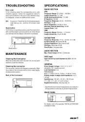
... the connector
The connector needs to be erased if...the surface with a pointed object such as a pencil, etc.
REAR PANEL
For details, refer to solve such problems. If the error code indication does not disappear, ... More than 60 dB S/N Ratio: More than 90 dB Wow/Flutter: Unmeasurable
AUDIO SECTION
Max. E03 Focus error.
TROUBLESHOOTING
Error code In the following cases the corresponding...
Service Manual - Page 2
... WHEN SERVICING ...5 ELECTRICAL PARTS LIST (CDC-X227) ...6 ~ 10 ELECTRICAL PARTS LIST (CZA-4 SNYNF) ...11 ~ 13 ELECTRICAL PARTS LIST (BZG-3 BNF) ...14 TRANSISTOR ILLUSTRATION ...15 WIRING - 1 (MAIN) ...16 SCHEMATIC DIAGRAM - 1 (MAIN) ...17 WIRING - 2 (FRONT / AUX) ...18 WIRING - 2 (FRONT) ...19 SCHEMATIC DIAGRAM - 2 (FRONT / AUX) ...20 WIRING - 3 (CD) ...21 WIRING - 3 (CD) ...22 SCHEMATIC DIAGRAM...
Service Manual - Page 8
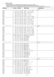
...-080 IC,PST994D O J 0101 8Z-KT1-614-010 ANT,AW-002 O J 0401 87-A61-225-110 JACK,PIN 2P XR-401
CDC-X227 YZSF a a a a a a a a a a
MAIN MAIN MAIN MAIN MAIN MAIN MAIN MAIN MAIN MAIN
...0551 87-010-759-080 C-CAP,U 0.1-25 Z F CM/CB O C 0801 87-012-278-080 C-CAP,U 2200P-50 K B GRM
SUFFIX&MODEL
CDC-X227 YZSF a a a a a a a a a a
MAIN MAIN MAIN MAIN MAIN MAIN MAIN MAIN MAIN MAIN
O C 0804 87-012-278-080 ...
Service Manual - Page 10
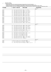
... J X R 0834 88-118-102-080 C-RES,S 1K-1/10W J O R 0902 88-108-823-080 C-RES,U 82K-1/16W J
SUFFIX&MODEL
CDC-X227 YZSF a a a a a a a a a a
MAIN MAIN MAIN MAIN MAIN MAIN MAIN MAIN MAIN MAIN
O R 0903 88-108-473-080...8C-KCG-622-010 TU UNIT, FAE347-A31 X W 0801 8A-KCG-615-010 WIRE,400 P-MUTE O X 0901 87-A70-362-080 VIB,XTAL 4.5MHZ HC-49/U-S
CDC-X227 YZSF a a a a
- 10 - ! = ! SAFETY PARTS C = ...
Service Manual - Page 18

WIRING - 2 (FRONT / AUX)
32
31
30
29
28
27
26
25
24
23
22
21
20
19
18
17
16
15
14
13
12
11
10
9
8
7
6
5
4
3
2
1
A
B
C
D
E
F
G
H
I
J
K
L
M
N
O
P
Q
R
S
T
U
- 18 -
Service Manual - Page 19
WIRING - 2 (FRONT)
1
2
3
4
5
6
7
8
9
10
11
12
13
14
15
16
17
18
19
20
21
22
23
24
25
26
27
28
29
30
31
32
A
B
C
D
E
F
G
H
I
J
K
L
M
N
O
P
Q
R
S
T
U
- 19 -
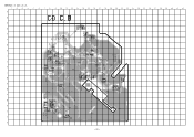
Service Manual - Page 21
WIRING - 3 (CD)
32
31
30
29
28
27
26
25
24
23
22
21
20
19
18
17
16
15
14
13
12
11
10
9
8
7
6
5
4
3
2
1
A
B
C
D
E
F
G
H
I
J
K
L
M
N
O
P
Q
R
S
T
U
- 21 -
Service Manual - Page 22
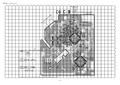
WIRING - 3 (CD)
1
2
3
4
5
6
7
8
9
10
11
12
13
14
15
16
17
18
19
20
21
22
23
24
25
26
27
28
29
30
31
32
A
B
C
D
E
F
G
H
I
J
K
L
M
N
O
P
Q
R
S
T
U
- 22 -
Service Manual - Page 24
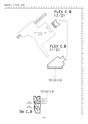
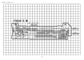
WIRING - 4 (FLEX / SW)
15
14
13
12
11
10
9
8
7
6
5
4
3
2
1
A
B
C
D
E
F
G
H
I
J
K
L
M
N
TO CD C.B
O
P
TO CD C.B
Q
R
S
T
U
- 24 -
Service Manual - Page 26
- 26 -
Service Manual - Page 28
...
O
RW disc control. Normal set to "H".
38
LP UP
O
RW disc control. Stereo signal input when receiving. Pin Name
I/O
Description
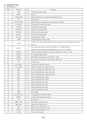
1
XIN
I
Channel detection signal input when FM/AM seeking.
IC DESCRIPTION
IC, LC72358N-9A71
Pin No. Not used.
3
CD DATA IN
I
Input data signal for DSP. Power supply.
32
E-VOL CLO
O
Clock...
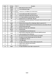
Service Manual - Page 29
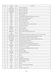
VDD
- XOUT
O
Description Audio mute signal output. Power control signal output. Rotary encoder input 2. Rotary encoder input 1. Not used . Voltage input for FM... 56 57 58 59 60 61 62 63 64 65 66 67 68 69 70 71 72 73 74 75 76 77 78 79 80
Pin Name
I/O
A-MUTE
O
POWER CONT
O
ST-BY MUTE
O
POWER MUTE O
BEEP
O
DFP IN
I
DRF
I
WRQ
I
RWC
O
CD RES
O
OPEN
I
SW2
I
SW1
I...
Service Manual - Page 30
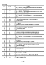
...
I /O
Description
For the connection of the FE signal between the TD and VR pins.
For the connection of a resistor which sets the gain of the pickup photodiode.
... signal to the CV+ and CV-
I
Composes the tracking phase compensation constant between this pin and the O
TE pin.
I
TES (track error sense) comparator input.
O
Sled control signal output.
O
For...
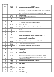
Service Manual - Page 31
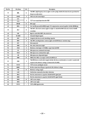
...range.
-
The FSS (focus search select) signal switches the focus search modes (+/-search / +search with the RFSM pin. For the connection of digital signals. I
respect to the reference voltage). (Connected to control the DSP's data ...is used to control the DSP's data slice level of a capacitor to hold the RF signal bottom.
Pin No.
37
38 39 40 41 42
43
44 45 46 47 48 49 50 51 52 53 ...
Service Manual - Page 32
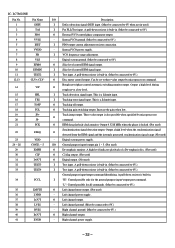
.... O
Tracking gain switching output. O
EFM data playback clock monitor.
I/O General purpose input/ output pin 1 ~ 5. (Not used )
I
For PLL/Test input. Left channel ground. (Must be... synchronization signal range.(Not used .)
I
Test input. I
Tracking error signal input.
IC, LC78622NE
Pin No. Internal VCO ground. (Must be connected to 0V.)
O
Disc motor control output. I...
Service Manual - Page 33
... output. (Not used )
I
Subcode read out clock input. I
(Must be connected to 0 V.)
O
Output pin for the 7.35 kHZ synchronization signal divided from control microprocessor. This is first applied. I
-
No pull-down resistor....
This is a Schmitt input. (Must be connected to 0 V.)
I
Read/write control input. Pin No. 42 43 44 45 46 47 48 49
50
51 52 53 54 55 56
57
58 59...
Service Manual - Page 34
...for bass and treble in the tone control circuits.
-
I
Super bass input.
IC, LC75374E Pin No. 1 2
Pin Name RVR IN R COM
3 ~ 5
RT1 ~ RT3
6
RT OUT
7
RS IN
8...low impedance.
- A low-frequency compensation capacitors must be connected between T1 and T2. I
Signal input pins.
-
Must be driven at a low impedance.
Must be driven at a low impedance.
- A ...
Service Manual - Page 45
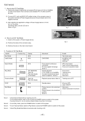
...Then connect a wire between Pin 73 (VDD) and Pin 63 (test).
2) Connect ACC (red) and BACK UP (yellow) wires of the connector...Pin 63 (test) of CD Test Mode
MODE
Function Key
Start Mode
Load/Unload
Display All lit.
PU lens repeats full swings. (Note 1) Normal playback If TOC READ is not available, the same movement as focus search is applied. (Note 2)
Playback pause status (Note 3)
Details...
Similar Questions

Need Wire Harness Diagram
Need picture of CDC-x227 wire harness diagram for head unit.
Need picture of CDC-x227 wire harness diagram for head unit.
(Posted by jvielbaum 6 years ago)

I Dont Have The Universal Remote Code For My Aiwa Cx-na50 Radio So I Need It
(Posted by Anonymous-145492 9 years ago)

I Need A Pinout Diagram For A Cdc-x144
no Harness But Need To Wire The Radio In Hard
no Harness But Need To Wire The Radio In Hard
(Posted by JIMMYKAYLA77 10 years ago)

Aiwa Cdc X504mp3, Looking For The Wiring Harness
instruction manuals or diagram showing wire diagram for speaker set up
instruction manuals or diagram showing wire diagram for speaker set up
(Posted by curtistice1 11 years ago)
