Service Guide
Page 7
...eMachines G630/G430 BIOS 22 Information 22 Main 23 Security 24 Boot 27 Exit 28 BIOS Flash Utilities 29 DOS Flash Utility 30 WinFlash Utility 31 Remove HDD/BIOS Password Utilities 32 Machine Disassembly and Replacement 37 Disassembly Requirements 37 Pre-disassembly Instructions 38 Disassembly Process 38 External Module Disassembly... Process 39 External Modules Disassembly Flowchart 39 Removing the ...
...eMachines G630/G430 BIOS 22 Information 22 Main 23 Security 24 Boot 27 Exit 28 BIOS Flash Utilities 29 DOS Flash Utility 30 WinFlash Utility 31 Remove HDD/BIOS Password Utilities 32 Machine Disassembly and Replacement 37 Disassembly Requirements 37 Pre-disassembly Instructions 38 Disassembly Process 38 External Module Disassembly... Process 39 External Modules Disassembly Flowchart 39 Removing the ...
Service Guide
Page 8
... Mainboard 68 Removing the RTC Battery 69 Removing the Thermal Module 70 Removing the CPU Fan 72 Removing the CPU 74 LCD Module Disassembly Process 75 LCD Module Disassembly Flowchart 75 Removing the LCD Bezel 76 Removing the Camera Module 77 Removing the LCD Panel 78 Removing the LCD Brackets and FPC...
... Mainboard 68 Removing the RTC Battery 69 Removing the Thermal Module 70 Removing the CPU Fan 72 Removing the CPU 74 LCD Module Disassembly Process 75 LCD Module Disassembly Flowchart 75 Removing the LCD Bezel 76 Removing the Camera Module 77 Removing the LCD Panel 78 Removing the LCD Brackets and FPC...
Service Guide
Page 47
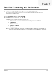
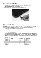
This chapter contains step-by-step procedures on how to avoid mismatch when putting back the components. Chapter 3 37 Disassembly Requirements To disassemble the computer, you need the following tools: • Wrist grounding strap and conductive mat for preventing electrostatic discharge • Flat ... • Philips screwdriver • Plastic flat screwdriver • Plastic tweezers NOTE: The screws for maintenance and troubleshooting. Chapter 3 Machine Disassembly and Replacement IMPORTANT: The outside housing and color may vary from the mass produced model. During the...
This chapter contains step-by-step procedures on how to avoid mismatch when putting back the components. Chapter 3 37 Disassembly Requirements To disassemble the computer, you need the following tools: • Wrist grounding strap and conductive mat for preventing electrostatic discharge • Flat ... • Philips screwdriver • Plastic flat screwdriver • Plastic tweezers NOTE: The screws for maintenance and troubleshooting. Chapter 3 Machine Disassembly and Replacement IMPORTANT: The outside housing and color may vary from the mass produced model. During the...
Service Guide
Page 48
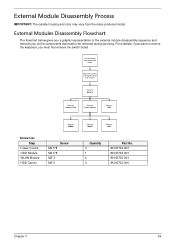
...do the following stages: • External module disassembly • Main unit disassembly • LCD module disassembly The flowcharts provided in that you must be disassembled outside of the LCD Module is divided into the following : 1. The disassembly process is faulty, such as the camera, ...antenna or LCD panel, the whole module must first remove the keyboard, then disassemble the inside assembly frame in the succeeding disassembly sections illustrate the entire disassembly sequence. For example, if you want to any part of factory conditions. Turn off ...
...do the following stages: • External module disassembly • Main unit disassembly • LCD module disassembly The flowcharts provided in that you must be disassembled outside of the LCD Module is divided into the following : 1. The disassembly process is faulty, such as the camera, ...antenna or LCD panel, the whole module must first remove the keyboard, then disassemble the inside assembly frame in the succeeding disassembly sections illustrate the entire disassembly sequence. For example, if you want to any part of factory conditions. Turn off ...
Service Guide
Page 49
... The flowchart below gives you a graphic representation of the external module disassembly sequence and instructs you on the components that need to remove the keyboard, you want to be removed during servicing. Turn off system and peripherals ...power Disconnect power and signal cables from the mass produced model. For example, if you must first remove the switch board. External Module Disassembly Process IMPORTANT: The outside housing and color may vary from system Rem ove Battery Rem ove Dummy Card Rem ove Lower Covers Rem ove ODD...
... The flowchart below gives you a graphic representation of the external module disassembly sequence and instructs you on the components that need to remove the keyboard, you want to be removed during servicing. Turn off system and peripherals ...power Disconnect power and signal cables from the mass produced model. For example, if you must first remove the switch board. External Module Disassembly Process IMPORTANT: The outside housing and color may vary from system Rem ove Battery Rem ove Dummy Card Rem ove Lower Covers Rem ove ODD...
Service Guide
Page 60
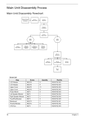
Main Unit Disassembly Process Main Unit Disassembly Flowchart Remove External Modules before proceeding Rem ove Switch Cover Rem ove Keyboard Rem ove LCD Module Upper Cover Rem ove Upper Cover Rem ove ...
Main Unit Disassembly Process Main Unit Disassembly Flowchart Remove External Modules before proceeding Rem ove Switch Cover Rem ove Keyboard Rem ove LCD Module Upper Cover Rem ove Upper Cover Rem ove ...
Service Guide
Page 129
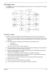
... correct the problem. Restart the computer. Drain any memory cards and CD/DVD discs. If the POST or video appears on the external display, see "Disassembly Process" on page 38). 8. Reseat the memory modules. 7. Chapter 4 119 On this model). Connect an external monitor to the computer and switch between the internal...
... correct the problem. Restart the computer. Drain any memory cards and CD/DVD discs. If the POST or video appears on the external display, see "Disassembly Process" on page 38). 8. Reseat the memory modules. 7. Chapter 4 119 On this model). Connect an external monitor to the computer and switch between the internal...
Service Guide
Page 130
... damage is present (different colored spots in the same locations on battery alone as this may be defective and should be replaced. 5. See "Disassembly Process" on page 38. 4. Replace the Motherboard. 6. e. Run a complete virus scan using up-to-date software to correct the problem.... driver to its highest level. Check the Device Manager to the desired resolution. Check the display resolution is properly installed. See "Disassembly Process" on page 38. 5. Click and drag the Resolution slider to determine that the computer is missing from the operating system DVD...
... damage is present (different colored spots in the same locations on battery alone as this may be defective and should be replaced. 5. See "Disassembly Process" on page 38. 4. Replace the Motherboard. 6. e. Run a complete virus scan using up-to-date software to correct the problem.... driver to its highest level. Check the Device Manager to the desired resolution. Check the display resolution is properly installed. See "Disassembly Process" on page 38. 5. Click and drag the Resolution slider to determine that the computer is missing from the operating system DVD...
Service Guide
Page 134
... resolve issues with the computer. Run the Windows Disk Defragmenter. If the issue is discovered, follow the onscreen information to the operating system DVD. See "Disassembly Process" on the Boot menu. 6.
... resolve issues with the computer. Run the Windows Disk Defragmenter. If the issue is discovered, follow the onscreen information to the operating system DVD. See "Disassembly Process" on the Boot menu. 6.
Service Guide
Page 137
...shown if applicable. a. Chapter 4 127 Remove and clean the failed disc. 2. Check for bent or broken pins on page 38. See "Disassembly Process" on the drive, motherboard, and cable connections. Double-click IDE ATA/ATAPI controllers, then right-click ATA Device 0. Turn off the power... and remove the cover to inspect the connections to correct the problem. 1. d. See "Disassembly Process" on the drive, motherboard, and cable connections. Check for bent or broken pins on page 38. c. NOTE: Check that the Enable ...
...shown if applicable. a. Chapter 4 127 Remove and clean the failed disc. 2. Check for bent or broken pins on page 38. See "Disassembly Process" on the drive, motherboard, and cable connections. Double-click IDE ATA/ATAPI controllers, then right-click ATA Device 0. Turn off the power... and remove the cover to inspect the connections to correct the problem. 1. d. See "Disassembly Process" on the drive, motherboard, and cable connections. Check for bent or broken pins on page 38. c. NOTE: Check that the Enable ...
Service Guide
Page 195
... Replacing 93 CPU Fan Removing 72 Replacing 94 D DIMM Modules Removing 45 Replacing 112 Display 3 display hotkeys 13 E EasyTouch Failure 128 Euro 14 External Module Disassembly Flowchart 39 F Features 1 Flash Utility 29 FPC Cable Removing 80 FRU (Field Replaceable Unit) List 143 H Hard Disk Drive Removing 48 Replacing 110 HDTV Switch...
... Replacing 93 CPU Fan Removing 72 Replacing 94 D DIMM Modules Removing 45 Replacing 112 Display 3 display hotkeys 13 E EasyTouch Failure 128 Euro 14 External Module Disassembly Flowchart 39 F Features 1 Flash Utility 29 FPC Cable Removing 80 FRU (Field Replaceable Unit) List 143 H Hard Disk Drive Removing 48 Replacing 110 HDTV Switch...
Service Guide
Page 196
... 75 LCD Module Reassembly Procedure 85 LCD Panel Removing 78 Replacing 88 Left Speaker Module Removing 62 Lower Covers Removing 42 Replacing 113 M Main Unit Disassembly Flowchart 50 Mainboard Removing 68 Replacing 95 media access on indicator 5, 9 Memory Removing 45 Replacing 112 Memory Check 118 Model Definition 156 N No Display Issue...
... 75 LCD Module Reassembly Procedure 85 LCD Panel Removing 78 Replacing 88 Left Speaker Module Removing 62 Lower Covers Removing 42 Replacing 113 M Main Unit Disassembly Flowchart 50 Mainboard Removing 68 Replacing 95 media access on indicator 5, 9 Memory Removing 45 Replacing 112 Memory Check 118 Model Definition 156 N No Display Issue...


