Service Guide
Page 7
...eMachines G630/G430 BIOS 22 Information 22 Main 23 Security 24 Boot 27 Exit 28 BIOS Flash Utilities 29 DOS Flash Utility 30 WinFlash Utility 31 Remove HDD/BIOS Password Utilities 32 Machine Disassembly and Replacement 37 Disassembly Requirements 37 Pre-disassembly Instructions 38 Disassembly Process 38 External Module Disassembly... Process 39 External Modules Disassembly Flowchart 39 Removing the ...
...eMachines G630/G430 BIOS 22 Information 22 Main 23 Security 24 Boot 27 Exit 28 BIOS Flash Utilities 29 DOS Flash Utility 30 WinFlash Utility 31 Remove HDD/BIOS Password Utilities 32 Machine Disassembly and Replacement 37 Disassembly Requirements 37 Pre-disassembly Instructions 38 Disassembly Process 38 External Module Disassembly... Process 39 External Modules Disassembly Flowchart 39 Removing the ...
Service Guide
Page 8
... Mainboard 68 Removing the RTC Battery 69 Removing the Thermal Module 70 Removing the CPU Fan 72 Removing the CPU 74 LCD Module Disassembly Process 75 LCD Module Disassembly Flowchart 75 Removing the LCD Bezel 76 Removing the Camera Module 77 Removing the LCD Panel 78 Removing the LCD Brackets and FPC...
... Mainboard 68 Removing the RTC Battery 69 Removing the Thermal Module 70 Removing the CPU Fan 72 Removing the CPU 74 LCD Module Disassembly Process 75 LCD Module Disassembly Flowchart 75 Removing the LCD Bezel 76 Removing the Camera Module 77 Removing the LCD Panel 78 Removing the LCD Brackets and FPC...
Service Guide
Page 47
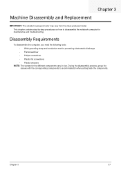
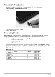
... with the corresponding components to disassemble the notebook computer for the different components vary in size. This chapter contains step-by-step procedures on how to avoid mismatch when putting back the components. Chapter 3 Machine Disassembly and Replacement IMPORTANT: The outside... housing and color may vary from the mass produced model. Disassembly Requirements To disassemble the computer, you need the following tools: • Wrist grounding strap...
... with the corresponding components to disassemble the notebook computer for the different components vary in size. This chapter contains step-by-step procedures on how to avoid mismatch when putting back the components. Chapter 3 Machine Disassembly and Replacement IMPORTANT: The outside... housing and color may vary from the mass produced model. Disassembly Requirements To disassemble the computer, you need the following tools: • Wrist grounding strap...
Service Guide
Page 48
... power to remove the mainboard, you do the following stages: • External module disassembly • Main unit disassembly • LCD module disassembly The flowcharts provided in that you must be disassembled outside of the LCD Module is divided into the following : 1. Place the system ...camera, antenna or LCD panel, the whole module must first remove the keyboard, then disassemble the inside assembly frame in the succeeding disassembly sections illustrate the entire disassembly sequence. Main Screw List Screw Quantity Part Number SCREW M2.5*4 1 86.N3702.001 SCREW...
... power to remove the mainboard, you do the following stages: • External module disassembly • Main unit disassembly • LCD module disassembly The flowcharts provided in that you must be disassembled outside of the LCD Module is divided into the following : 1. Place the system ...camera, antenna or LCD panel, the whole module must first remove the keyboard, then disassemble the inside assembly frame in the succeeding disassembly sections illustrate the entire disassembly sequence. Main Screw List Screw Quantity Part Number SCREW M2.5*4 1 86.N3702.001 SCREW...
Service Guide
Page 49
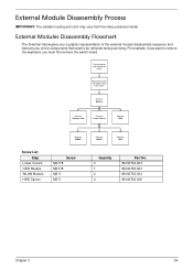
... and instructs you on the components that need to remove the keyboard, you want to be removed during servicing. External Module Disassembly Process IMPORTANT: The outside housing and color may vary from system Rem ove Battery Rem ove Dummy Card Rem ove Lower Covers Rem ove ODD ...
... and instructs you on the components that need to remove the keyboard, you want to be removed during servicing. External Module Disassembly Process IMPORTANT: The outside housing and color may vary from system Rem ove Battery Rem ove Dummy Card Rem ove Lower Covers Rem ove ODD ...
Service Guide
Page 60
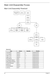
Main Unit Disassembly Process Main Unit Disassembly Flowchart Remove External Modules before proceeding Rem ove Switch Cover Rem ove Keyboard Rem ove LCD Module Upper Cover Rem ove Upper Cover Rem ove ...
Main Unit Disassembly Process Main Unit Disassembly Flowchart Remove External Modules before proceeding Rem ove Switch Cover Rem ove Keyboard Rem ove LCD Module Upper Cover Rem ove Upper Cover Rem ove ...
Service Guide
Page 129
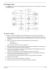
... following occurs: • Fans start up • Status LEDs light up If there is selected. Make sure that the internal display is no power, see "Disassembly Process" on page 118. 3. Reconnect the power and reboot the computer. 4. Remove the drives (see "Power On Issue" on page 38). 8.
... following occurs: • Fans start up • Status LEDs light up If there is selected. Make sure that the internal display is no power, see "Disassembly Process" on page 118. 3. Reconnect the power and reboot the computer. 4. Remove the drives (see "Power On Issue" on page 38). 8.
Service Guide
Page 130
...information is not running on page 183. 10. If the Issue is faulty and should be replaced. Reboot the computer. 2. See "Disassembly Process" on the desktop and select Personalize´ Display Settings. If the display is too dim at the highest brightness setting, the ... be replaced. 5. Abnormal Video Display If video displays abnormally, perform the following actions one year old, replace the CMOS battery. 2. See "Disassembly Process" on page 183. 120 Chapter 4 b. If the BIOS settings are no device conflicts. • No hardware is experiencing HDD or...
...information is not running on page 183. 10. If the Issue is faulty and should be replaced. Reboot the computer. 2. See "Disassembly Process" on the desktop and select Personalize´ Display Settings. If the display is too dim at the highest brightness setting, the ... be replaced. 5. Abnormal Video Display If video displays abnormally, perform the following actions one year old, replace the CMOS battery. 2. See "Disassembly Process" on page 183. 120 Chapter 4 b. If the BIOS settings are no device conflicts. • No hardware is experiencing HDD or...
Service Guide
Page 134
... Finish. Check the BIOS settings are required. For more information see Windows Help and Support. 10. For more information see Windows Help and Support. 5. See "Disassembly Process" on the Boot menu. 6. insert the Windows 7 Operating System DVD in the ODD and restart the computer. b. c. d. e. The System Recovery Options screen displays. h. If...
... Finish. Check the BIOS settings are required. For more information see Windows Help and Support. 10. For more information see Windows Help and Support. 5. See "Disassembly Process" on the Boot menu. 6. insert the Windows 7 Operating System DVD in the ODD and restart the computer. b. c. d. e. The System Recovery Options screen displays. h. If...
Service Guide
Page 137
...all cables are connected correctly. 5. Listen to correct the problem. 1. Check for bent or broken pins on the Information page. d. See "Disassembly Process" on page 38. Check for bent or broken pins on page 15. 3. Test the drive using other ATA Devices shown if applicable.... connections to correct the problem. 1. c. Turn off the power and remove the cover to inspect the connections to enter the BIOS Utility. 2. See "Disassembly Process" on page 38. Check for broken connectors on the drive, motherboard, and cables. d. e. Play a DVD movie f. c. Try an alternate ...
...all cables are connected correctly. 5. Listen to correct the problem. 1. Check for bent or broken pins on the Information page. d. See "Disassembly Process" on page 38. Check for bent or broken pins on page 15. 3. Test the drive using other ATA Devices shown if applicable.... connections to correct the problem. 1. c. Turn off the power and remove the cover to inspect the connections to enter the BIOS Utility. 2. See "Disassembly Process" on page 38. Check for broken connectors on the drive, motherboard, and cables. d. e. Play a DVD movie f. c. Try an alternate ...
Service Guide
Page 195
... Replacing 93 CPU Fan Removing 72 Replacing 94 D DIMM Modules Removing 45 Replacing 112 Display 3 display hotkeys 13 E EasyTouch Failure 128 Euro 14 External Module Disassembly Flowchart 39 F Features 1 Flash Utility 29 FPC Cable Removing 80 FRU (Field Replaceable Unit) List 143 H Hard Disk Drive Removing 48 Replacing 110 HDTV Switch...
... Replacing 93 CPU Fan Removing 72 Replacing 94 D DIMM Modules Removing 45 Replacing 112 Display 3 display hotkeys 13 E EasyTouch Failure 128 Euro 14 External Module Disassembly Flowchart 39 F Features 1 Flash Utility 29 FPC Cable Removing 80 FRU (Field Replaceable Unit) List 143 H Hard Disk Drive Removing 48 Replacing 110 HDTV Switch...
Service Guide
Page 196
... 75 LCD Module Reassembly Procedure 85 LCD Panel Removing 78 Replacing 88 Left Speaker Module Removing 62 Lower Covers Removing 42 Replacing 113 M Main Unit Disassembly Flowchart 50 Mainboard Removing 68 Replacing 95 media access on indicator 5, 9 Memory Removing 45 Replacing 112 Memory Check 118 Model Definition 156 N No Display Issue...
... 75 LCD Module Reassembly Procedure 85 LCD Panel Removing 78 Replacing 88 Left Speaker Module Removing 62 Lower Covers Removing 42 Replacing 113 M Main Unit Disassembly Flowchart 50 Mainboard Removing 68 Replacing 95 media access on indicator 5, 9 Memory Removing 45 Replacing 112 Memory Check 118 Model Definition 156 N No Display Issue...


