
User Guide
Page 5
See "Removing the Battery Pack" on page 53. 2. Grasp the ODD by the bezel and slide it out of the chassis. Removing the ODD Module 1. Step ODD Module Disassembly Size M2.5*6.5 Quantity 1 3. Screw Type Chapter 3 57 Remove the one (1) screw securing the ODD module in place.
See "Removing the Battery Pack" on page 53. 2. Grasp the ODD by the bezel and slide it out of the chassis. Removing the ODD Module 1. Step ODD Module Disassembly Size M2.5*6.5 Quantity 1 3. Screw Type Chapter 3 57 Remove the one (1) screw securing the ODD module in place.
User Guide
Page 6
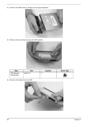
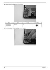
Remove the two screws securing the ODD bracket. Remove the ODD bezel by rotating the top edge downward. 5. 4. Remove the bracket from the ODD. Quantity 2 Screw Type 58 Chapter 3 Step ODD Bracket Disassembly Size M2.0*3.0 6.
Remove the two screws securing the ODD bracket. Remove the ODD bezel by rotating the top edge downward. 5. 4. Remove the bracket from the ODD. Quantity 2 Screw Type 58 Chapter 3 Step ODD Bracket Disassembly Size M2.0*3.0 6.

User Guide
Page 7
Main Unit Disassembly Process Main Unit Disassembly Flowchart NOTE: Use the process highlighted in red to access the Bluetooth module Screw List Step Lower Cover Battery Bay WLAN Module Disassembly USB Module Disassembly HDD Module Screw M2.5*6.5 M2.0*3.0 M2.0*3.0 M2.5*4.0 M2-0.4*2 Quantity 17 6 1 1 1 Part No. 86.ARE07.001 86.ARE07.002 86.ARE07.002 86.ARE07.002 86.W4107.002 Chapter 3 59
Main Unit Disassembly Process Main Unit Disassembly Flowchart NOTE: Use the process highlighted in red to access the Bluetooth module Screw List Step Lower Cover Battery Bay WLAN Module Disassembly USB Module Disassembly HDD Module Screw M2.5*6.5 M2.0*3.0 M2.0*3.0 M2.5*4.0 M2-0.4*2 Quantity 17 6 1 1 1 Part No. 86.ARE07.001 86.ARE07.002 86.ARE07.002 86.ARE07.002 86.W4107.002 Chapter 3 59

User Guide
Page 8
Part No. 86.N1407.007 86.ARE07.001 86.R6Z07.001 86.R6Z07.001 Step Lower Cover (red callout) Battery Bay (green callout) Size M2.5*6.5 M2.0*3.0 Quantity 17 6 Screw Type 60 Chapter 3 See "External Modules Disassembly Process" on page 52. 2. Step HDD Carrier Disassembly LCD Module Disassembly Thermal Module Disassembly Mainboard Disassembly Screw M3.0*3.5 M2.5*6.5 M2.5*4.0 M2.5*4.0 Quantity 4 4 1 1 Removing the Lower Cover 1. Remove the twenty three (23) securing screws from the lower cover.
Part No. 86.N1407.007 86.ARE07.001 86.R6Z07.001 86.R6Z07.001 Step Lower Cover (red callout) Battery Bay (green callout) Size M2.5*6.5 M2.0*3.0 Quantity 17 6 Screw Type 60 Chapter 3 See "External Modules Disassembly Process" on page 52. 2. Step HDD Carrier Disassembly LCD Module Disassembly Thermal Module Disassembly Mainboard Disassembly Screw M3.0*3.5 M2.5*6.5 M2.5*4.0 M2.5*4.0 Quantity 4 4 1 1 Removing the Lower Cover 1. Remove the twenty three (23) securing screws from the lower cover.

User Guide
Page 10
See "Removing the Lower Cover" on page 60. 2. This section is an overview of the major components of the main unit. 1 23 9 8 Item 1 2 3 4 5 Description RTC battery LVDS cable Thermal module WLAN module DIMM module(s) 76 5 4 Item 6 7 8 9 Description CPU Bluetooth cable HDD USB module 62 Chapter 3 Disassembly Overview 1.
See "Removing the Lower Cover" on page 60. 2. This section is an overview of the major components of the main unit. 1 23 9 8 Item 1 2 3 4 5 Description RTC battery LVDS cable Thermal module WLAN module DIMM module(s) 76 5 4 Item 6 7 8 9 Description CPU Bluetooth cable HDD USB module 62 Chapter 3 Disassembly Overview 1.
User Guide
Page 11
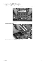
See "Disassembly Overview" on both sides of the DIMM socket to release the DIMM module. 3. Repeat steps for the second DIMM module if present. Remove the DIMM module. 4. Chapter 3 63 Removing the DIMM Modules 1. Push out the release latches on page 62. 2.
See "Disassembly Overview" on both sides of the DIMM socket to release the DIMM module. 3. Repeat steps for the second DIMM module if present. Remove the DIMM module. 4. Chapter 3 63 Removing the DIMM Modules 1. Push out the release latches on page 62. 2.
User Guide
Page 12
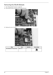
Step WLAN Module Disassembly Size M2.0*3.0 Quantity 1 Screw Type 64 Chapter 3 Removing the WLAN Module 1. Disconnect the two (2) cables from the WLAN board. 3. See "Disassembly Overview" on page 62. 2. Remove the one (1) screw.
Step WLAN Module Disassembly Size M2.0*3.0 Quantity 1 Screw Type 64 Chapter 3 Removing the WLAN Module 1. Disconnect the two (2) cables from the WLAN board. 3. See "Disassembly Overview" on page 62. 2. Remove the one (1) screw.
User Guide
Page 13
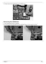
See "Disassembly Overview" on page 62. 2. Repeat for the mainboard connector. Detach and remove the WLAN board from the USB board. Unlock and disconnect the USB FFC from the WLAN socket. Chapter 3 65 Removing the USB Board 1. 4.
See "Disassembly Overview" on page 62. 2. Repeat for the mainboard connector. Detach and remove the WLAN board from the USB board. Unlock and disconnect the USB FFC from the WLAN socket. Chapter 3 65 Removing the USB Board 1. 4.
User Guide
Page 14
Lift the USB board upward and away from the USB board. Step USB Module Disassembly Size M2.5*4.0 Quantity 1 4. Remove the one (1) screw from the chassis. Screw Type 66 Chapter 3 3.
Lift the USB board upward and away from the USB board. Step USB Module Disassembly Size M2.5*4.0 Quantity 1 4. Remove the one (1) screw from the chassis. Screw Type 66 Chapter 3 3.
User Guide
Page 15
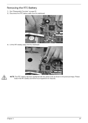
NOTE: The RTC battery has been highlighted with the yellow circle as shown in the previous image. Removing the RTC Battery 1. Lift the RTC battery away from the mainboard. 3. Chapter 3 67 See "Disassembly Overview" on page 62. 2. Please detach the RTC battery and follow local regulations for disposal. Disconnect the RTC battery cable from the mainboard.
NOTE: The RTC battery has been highlighted with the yellow circle as shown in the previous image. Removing the RTC Battery 1. Lift the RTC battery away from the mainboard. 3. Chapter 3 67 See "Disassembly Overview" on page 62. 2. Please detach the RTC battery and follow local regulations for disposal. Disconnect the RTC battery cable from the mainboard.

User Guide
Page 16
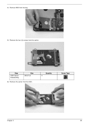
Using the pull-tab, slide the HDD module in the direction of the arrow to the mainboard. Step HDD Module Size M2-0.4*2 Quantity 1 Screw Type 3. Removing the HDD Module 1. See "Disassembly Overview" on page 62. 2. Remove the one (1) screw securing the HDD module to disconnect the interface. 68 Chapter 3
Using the pull-tab, slide the HDD module in the direction of the arrow to the mainboard. Step HDD Module Size M2-0.4*2 Quantity 1 Screw Type 3. Removing the HDD Module 1. See "Disassembly Overview" on page 62. 2. Remove the one (1) screw securing the HDD module to disconnect the interface. 68 Chapter 3
User Guide
Page 17
Remove the carrier from the carrier. 4. Step HDD Carrier Disassembly Size M3.0*3.5 6. Quantity 4 Screw Type Chapter 3 69 Remove the four (4) screws from the HDD. Remove HDD from the bay. 5.
Remove the carrier from the carrier. 4. Step HDD Carrier Disassembly Size M3.0*3.5 6. Quantity 4 Screw Type Chapter 3 69 Remove the four (4) screws from the HDD. Remove HDD from the bay. 5.
User Guide
Page 18
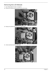
Remove the WLAN antennas from the fan housing. 3. Unlock and disconnect the LVDS cable. 70 Chapter 3 See "Disassembly Overview" on page 62. 2. Removing the LCD Module 1. Remove the adhesive ground wire from the cable guides. 4.
Remove the WLAN antennas from the fan housing. 3. Unlock and disconnect the LVDS cable. 70 Chapter 3 See "Disassembly Overview" on page 62. 2. Removing the LCD Module 1. Remove the adhesive ground wire from the cable guides. 4.
User Guide
Page 19
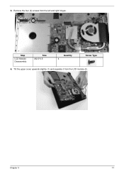
Remove the four (4) screws from the LCD module (2). 2 1 Chapter 3 71 Step LCD Module Disassembly Size M2.5*6.5 Quantity 4 Screw Type 6. 5. Tilt the upper cover upwards slightly (1) and separate it from the left and right hinges.
Remove the four (4) screws from the LCD module (2). 2 1 Chapter 3 71 Step LCD Module Disassembly Size M2.5*6.5 Quantity 4 Screw Type 6. 5. Tilt the upper cover upwards slightly (1) and separate it from the left and right hinges.
User Guide
Page 20
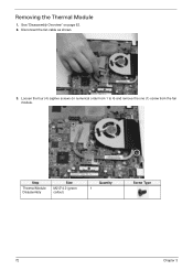
See "Disassembly Overview" on page 62. 2. Disconnect the fan cable as shown. 3. Loosen the four (4) captive screws (in numerical order from 1 to 4) and remove the one (1) screw from the fan module. 4 1 3 Step Thermal Module Disassembly Size M2.5*4.0 (green callout) 2 Quantity 1 Screw Type 72 Chapter 3 Removing the Thermal Module 1.
See "Disassembly Overview" on page 62. 2. Disconnect the fan cable as shown. 3. Loosen the four (4) captive screws (in numerical order from 1 to 4) and remove the one (1) screw from the fan module. 4 1 3 Step Thermal Module Disassembly Size M2.5*4.0 (green callout) 2 Quantity 1 Screw Type 72 Chapter 3 Removing the Thermal Module 1.

User Guide
Page 23
Quantity 1 Screw Type Chapter 3 75 Remove the one (1) securing screw from the mainboard. Step Mainboard Disassembly Size M2.5*4.0 4. Lift the mainboard away the lower cover. 3.
Quantity 1 Screw Type Chapter 3 75 Remove the one (1) securing screw from the mainboard. Step Mainboard Disassembly Size M2.5*4.0 4. Lift the mainboard away the lower cover. 3.
User Guide
Page 28
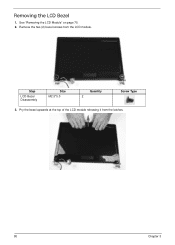
Pry the bezel upwards at the top of the LCD module releasing it from the LCD module. See "Removing the LCD Module" on page 70. 2. Removing the LCD Bezel 1. Remove the two (2) bezel screws from the latches. 80 Chapter 3 Step LCD Bezel Disassembly Size M2.5*5.0 Quantity 2 Screw Type 3.
Pry the bezel upwards at the top of the LCD module releasing it from the LCD module. See "Removing the LCD Module" on page 70. 2. Removing the LCD Bezel 1. Remove the two (2) bezel screws from the latches. 80 Chapter 3 Step LCD Bezel Disassembly Size M2.5*5.0 Quantity 2 Screw Type 3.
User Guide
Page 31
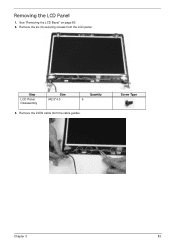
See "Removing the LCD Bezel" on page 80. 2. Removing the LCD Panel 1. Remove the six (6) securing screws from the cable guides. Step LCD Panel Disassembly Size M2.5*4.0 Quantity 6 3. Remove the LVDS cable from the LCD panel. Screw Type Chapter 3 83
See "Removing the LCD Bezel" on page 80. 2. Removing the LCD Panel 1. Remove the six (6) securing screws from the cable guides. Step LCD Panel Disassembly Size M2.5*4.0 Quantity 6 3. Remove the LVDS cable from the LCD panel. Screw Type Chapter 3 83
User Guide
Page 32
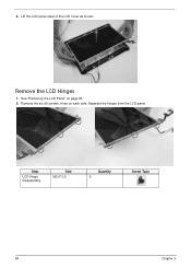
Remove the six (6) screws, three on page 83. 2. Separate the hinges from the LCD panel. Remove the LCD Hinges 1. Step LCD Hinge Disassembly Size M2.0*3.0 Quantity 6 Screw Type 84 Chapter 3 4. See "Removing the LCD Panel" on each side. Lift the LCD panel clear of the LCD cover as shown.
Remove the six (6) screws, three on page 83. 2. Separate the hinges from the LCD panel. Remove the LCD Hinges 1. Step LCD Hinge Disassembly Size M2.0*3.0 Quantity 6 Screw Type 84 Chapter 3 4. See "Removing the LCD Panel" on each side. Lift the LCD panel clear of the LCD cover as shown.


