eMachines Notebook User Guide (All Series)
Page 12
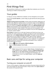
Quick Guide introduces you get started with language such as the eMachinesSystem User Guide mentioned below the LCD screen beside the easy-launch buttons. In addition it : 1 Click on Start, All Programs, eMachinesSystem. 2 Click on eMachinesSystem User Guide....complete the installation. xii First things first We would like to use your eMachines notebook, we have designed a set of the power button. Your guides To help you for making an eMachines notebook your computer. It covers basic topics such as system utilities, data recovery, expansion options and troubleshooting...
Quick Guide introduces you get started with language such as the eMachinesSystem User Guide mentioned below the LCD screen beside the easy-launch buttons. In addition it : 1 Click on Start, All Programs, eMachinesSystem. 2 Click on eMachinesSystem User Guide....complete the installation. xii First things first We would like to use your eMachines notebook, we have designed a set of the power button. Your guides To help you for making an eMachines notebook your computer. It covers basic topics such as system utilities, data recovery, expansion options and troubleshooting...
eMachines D620 Series Quick Guide
Page 5
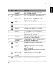
...Charging: The light shows amber when the battery is closed up. The front panel indicators are visible even when the computer cover is charging. 2. Num Lock Lights up when Caps Lock is activated. 5 Keyboard For entering data into your computer. 6... Palmrest Comfortable support area for sound recording. 3 Display screen Also called Liquid-Crystal Display (LCD), displays computer output. 4 HDD Indicates when the hard disk drive is activated. Battery1 Indicates the computer's batttery status. 1. Fully charged: The...
...Charging: The light shows amber when the battery is closed up. The front panel indicators are visible even when the computer cover is charging. 2. Num Lock Lights up when Caps Lock is activated. 5 Keyboard For entering data into your computer. 6... Palmrest Comfortable support area for sound recording. 3 Display screen Also called Liquid-Crystal Display (LCD), displays computer output. 4 HDD Indicates when the hard disk drive is activated. Battery1 Indicates the computer's batttery status. 1. Fully charged: The...
Service Guide
Page 48
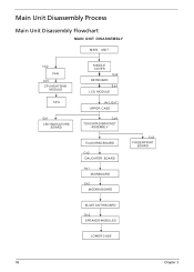
Main Unit Disassembly Process Main Unit Disassembly Flowchart MAIN UNIT DISASSEMBLY MAIN UNIT Hx2 FAN Ax5 CPU HEATSINK MODULE CPU Gx1 LED INDICATORS BOARD MIDDLE COVER Cx2 KEYBOARD Ex4 LCD MODULE Ax1, Ex11 UPPER CASE Cx4 TOUCHPAD BRACKET ASSEMBLY TOUCHPAD BOARD Cx2 DAUGHTER BOARD Ax1 MAINBOARD Cx2 MODEM BOARD Cx2 FINGERPRINT BOARD BLUETOOTH BOARD Dx2 SPEAKER MODULES LOWER CASE 58 Chapter 3
Main Unit Disassembly Process Main Unit Disassembly Flowchart MAIN UNIT DISASSEMBLY MAIN UNIT Hx2 FAN Ax5 CPU HEATSINK MODULE CPU Gx1 LED INDICATORS BOARD MIDDLE COVER Cx2 KEYBOARD Ex4 LCD MODULE Ax1, Ex11 UPPER CASE Cx4 TOUCHPAD BRACKET ASSEMBLY TOUCHPAD BOARD Cx2 DAUGHTER BOARD Ax1 MAINBOARD Cx2 MODEM BOARD Cx2 FINGERPRINT BOARD BLUETOOTH BOARD Dx2 SPEAKER MODULES LOWER CASE 58 Chapter 3
Service Guide
Page 52
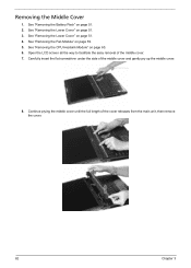
..." on page 51. 3. Open the LCD screen all the way to facilitate the easy removal of the middle cover and gently pry up the middle cover. 8. Carefully insert the flat screwdriver under the side of the middle cover. 7. Continue prying the middle cover until the full length of the cover releases from the main unit, then...
..." on page 51. 3. Open the LCD screen all the way to facilitate the easy removal of the middle cover and gently pry up the middle cover. 8. Carefully insert the flat screwdriver under the side of the middle cover. 7. Continue prying the middle cover until the full length of the cover releases from the main unit, then...
Service Guide
Page 54
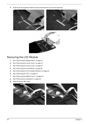
See "Removing the Lower Cover" on page 51. 2. See "Removing the Battery Pack" on page 51. 3. See "Removing the Lower Cover" on page 63. 9. See "Removing the Keyboard" on page 51. 4. Removing the LCD Module 1. See "Removing the CPU Heatsink Module" on page 61. 7. See "Removing the CPU" on page 60. 6. Disconnect the keyboard cable from the mainboard to remove the keyboard. See "Removing the Fan Module" on page 62. 8. See "Removing the Middle Cover" on page 59. 5. 5. Disconnect the LED cable. 64 Chapter 3
See "Removing the Lower Cover" on page 51. 2. See "Removing the Battery Pack" on page 51. 3. See "Removing the Lower Cover" on page 63. 9. See "Removing the Keyboard" on page 51. 4. Removing the LCD Module 1. See "Removing the CPU Heatsink Module" on page 61. 7. See "Removing the CPU" on page 60. 6. Disconnect the keyboard cable from the mainboard to remove the keyboard. See "Removing the Fan Module" on page 62. 8. See "Removing the Middle Cover" on page 59. 5. 5. Disconnect the LED cable. 64 Chapter 3
Service Guide
Page 57
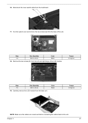
Remove the two screws (E) from the base of the LCD module. Color Black Torque 3.0 kgf-cm NOTE: Make sure the cables are routed well before connecting the cables back to the unit. Turn the system over and remove the two screws (E) from the left and right hinge of the unit. Chapter 3 67 Disconnect the cover switch cable from the base unit. Torque 3.0 kgf-cm Step 1~2 Size (Quantity) M2.5 x L6 (2) 19. 16. Step 1~2 Size (Quantity) M2.5 x L6 (2) Color Black 18. Carefully remove the LCD module from the mainboard. 17.
Remove the two screws (E) from the base of the LCD module. Color Black Torque 3.0 kgf-cm NOTE: Make sure the cables are routed well before connecting the cables back to the unit. Turn the system over and remove the two screws (E) from the left and right hinge of the unit. Chapter 3 67 Disconnect the cover switch cable from the base unit. Torque 3.0 kgf-cm Step 1~2 Size (Quantity) M2.5 x L6 (2) 19. 16. Step 1~2 Size (Quantity) M2.5 x L6 (2) Color Black 18. Carefully remove the LCD module from the mainboard. 17.
Service Guide
Page 58
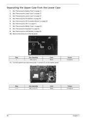
See "Removing the Battery Pack" on page 51. 3. See "Removing the Lower Cover" on page 51. 2. See "Removing the Middle Cover" on page 61. 7. See "Removing the CPU" on page 62. 8. See "Removing the Lower Cover" on the top panel. Remove the screw (A) on page 51. 4. Torque 1.6 kgf-cm Step ...1~11 Size (Quantity) M2.5 x L6 (11) Color Black Torque 3.0 kgf-cm 68 Chapter 3 See "Removing the Fan Module" on page 63. 9. See "Removing the Keyboard" on page 59. 5. See "Removing the LCD ...
See "Removing the Battery Pack" on page 51. 3. See "Removing the Lower Cover" on page 51. 2. See "Removing the Middle Cover" on page 61. 7. See "Removing the CPU" on page 62. 8. See "Removing the Lower Cover" on the top panel. Remove the screw (A) on page 51. 4. Torque 1.6 kgf-cm Step ...1~11 Size (Quantity) M2.5 x L6 (11) Color Black Torque 3.0 kgf-cm 68 Chapter 3 See "Removing the Fan Module" on page 63. 9. See "Removing the Keyboard" on page 59. 5. See "Removing the LCD ...

Service Guide
Page 59
... Heatsink Module" on page 61. 7. See "Removing the CPU" on page 60. 6. Removing the Touchpad Board Module 1. See "Removing the Lower Cover" on page 51. 2. Disconnect the touchpad cable from the lower case. See "Removing the Battery Pack" on page 51. 4. See "Removing the Middle... Cover" on page 64. 10. See "Removing the LCD Module" on page 62. 8. Remove the two screws (C) on the touchpad bracket. Step 1~4 Chapter 3 Size (Quantity) M2 x L3 (4)...
... Heatsink Module" on page 61. 7. See "Removing the CPU" on page 60. 6. Removing the Touchpad Board Module 1. See "Removing the Lower Cover" on page 51. 2. Disconnect the touchpad cable from the lower case. See "Removing the Battery Pack" on page 51. 4. See "Removing the Middle... Cover" on page 64. 10. See "Removing the LCD Module" on page 62. 8. Remove the two screws (C) on the touchpad bracket. Step 1~4 Chapter 3 Size (Quantity) M2 x L3 (4)...
Service Guide
Page 61
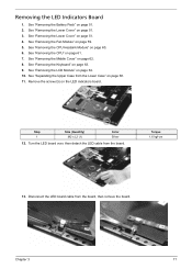
...8. Chapter 3 71 See "Removing the Middle Cover" on page 61. 7. Torque 1.6 kgf-cm 13. See "Removing the Battery Pack" on the LED indicators board. Remove the screw (G) on page 51. 2. Disconnect the LED board cable from the board. See "Removing the LCD Module" on page 51. 3. See "Removing... the Lower Cover" on page 64. 10. See "Separating the Upper Case from the Lower Case" on page 68. 11. Removing the...
...8. Chapter 3 71 See "Removing the Middle Cover" on page 61. 7. Torque 1.6 kgf-cm 13. See "Removing the Battery Pack" on the LED indicators board. Remove the screw (G) on page 51. 2. Disconnect the LED board cable from the board. See "Removing the LCD Module" on page 51. 3. See "Removing... the Lower Cover" on page 64. 10. See "Separating the Upper Case from the Lower Case" on page 68. 11. Removing the...
Service Guide
Page 62
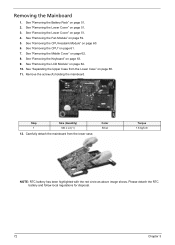
...RTC battery has been highlighted with the red circle as above image shows. See "Removing the Battery Pack" on page 62. 8. See "Removing the Lower Cover" on page 61. 7. See "Removing the CPU" on page 51. 3. Remove the screw (A) holding the mainboard. Please detach the RTC battery and ...follow local regulations for disposal. 72 Chapter 3 See "Removing the LCD Module" on page 59. 5. See "Separating the Upper Case from the lower case. See "Removing the Fan Module" on page 64. 10. See "...
...RTC battery has been highlighted with the red circle as above image shows. See "Removing the Battery Pack" on page 62. 8. See "Removing the Lower Cover" on page 61. 7. See "Removing the CPU" on page 51. 3. Remove the screw (A) holding the mainboard. Please detach the RTC battery and ...follow local regulations for disposal. 72 Chapter 3 See "Removing the LCD Module" on page 59. 5. See "Separating the Upper Case from the lower case. See "Removing the Fan Module" on page 64. 10. See "...

Service Guide
Page 63
... Upper Case from the Lower Case" on page 51. 3. Disconnect the modem board cable from modem board. 14. See "Removing the Lower Cover" on page 62. 8. See "Removing the Middle Cover" on page 51. 4. See "Removing the Mainboard" on page 60. 6. See "Removing the CPU Heatsink Module" on page 72. See "Removing... page 63. 9. Removing the Modem Board 1. See "Removing the CPU" on page 59. 5. 13. See "Removing the Fan Module" on page 61. 7. See "Removing the LCD Module" on page 64. 10. Chapter 3 73
... Upper Case from the Lower Case" on page 51. 3. Disconnect the modem board cable from modem board. 14. See "Removing the Lower Cover" on page 62. 8. See "Removing the Middle Cover" on page 51. 4. See "Removing the Mainboard" on page 60. 6. See "Removing the CPU Heatsink Module" on page 72. See "Removing... page 63. 9. Removing the Modem Board 1. See "Removing the CPU" on page 59. 5. 13. See "Removing the Fan Module" on page 61. 7. See "Removing the LCD Module" on page 64. 10. Chapter 3 73

Service Guide
Page 64
...the Mainboard" on page 51. 3. Detach the modem board from the Lower Case" on the modem board. See "Removing the LCD Module" on page 62. 8. See "Removing the Middle Cover" on page 64. 10. See "Separating the Upper Case from the mainboard. Remove the two screws (C) on page 68. ...11. Color Silver Torque 1.6 kgf-cm Removing the Speaker Modules 1. See "Removing the Lower Cover" on page 63. 9. See "Removing the Keyboard" on page 51. 4. Step 1~2 Size (Quantity) M2 x L3 (2) 13. See "Removing the CPU Heatsink...
...the Mainboard" on page 51. 3. Detach the modem board from the Lower Case" on the modem board. See "Removing the LCD Module" on page 62. 8. See "Removing the Middle Cover" on page 64. 10. See "Separating the Upper Case from the mainboard. Remove the two screws (C) on page 68. ...11. Color Silver Torque 1.6 kgf-cm Removing the Speaker Modules 1. See "Removing the Lower Cover" on page 63. 9. See "Removing the Keyboard" on page 51. 4. Step 1~2 Size (Quantity) M2 x L3 (2) 13. See "Removing the CPU Heatsink...

Service Guide
Page 67
..., Hx4) on page 62. 8. See "Removing the Lower Cover" on page 51. 4. See "Removing the Fan Module" on page 60. 6. Remove the six rounded screw caps as shown. See "Removing the CPU Heatsink Module" on page 59. 5. See "Removing the LCD Module" on page 61. 7. Torque 3.0 kgf-cm 3.0 kgf... Chapter 3 77 See "Removing the CPU" on page 64. 10. See "Removing the Battery Pack" on page 63. 9. Carefully pry open the LCD bezel and remove the bezel from the LCD module. See "Removing the Keyboard" on page 51. 2. Step 1~4 5~6 Size (Quantity) M2.5 x L5 (4) M2.5 x L6 (2) Color Black ...
..., Hx4) on page 62. 8. See "Removing the Lower Cover" on page 51. 4. See "Removing the Fan Module" on page 60. 6. Remove the six rounded screw caps as shown. See "Removing the CPU Heatsink Module" on page 59. 5. See "Removing the LCD Module" on page 61. 7. Torque 3.0 kgf-cm 3.0 kgf... Chapter 3 77 See "Removing the CPU" on page 64. 10. See "Removing the Battery Pack" on page 63. 9. Carefully pry open the LCD bezel and remove the bezel from the LCD module. See "Removing the Keyboard" on page 51. 2. Step 1~4 5~6 Size (Quantity) M2.5 x L5 (4) M2.5 x L6 (2) Color Black ...

Service Guide
Page 68
..." on page 77. 11. See "Removing the LCD Bezel" on page 64. 10. Step 1 Size (Quantity) M2.5 x L5 (1) 12. Color Black Torque 3 kgf-cm 78 Chapter 3 See "Removing the Fan Module" on page ... CPU" on page 63. 9. See "Removing the Keyboard" on page 61. 7. Turn the inverter board over. See "Removing the Middle Cover" on page 51. 3. Removing the Inverter Board 1. See "Removing the Lower Cover" on page 62. 8. See "Removing the Lower Cover" on page 60. 6. See "Removing the CPU Heatsink Module" on page 51. 4.
..." on page 77. 11. See "Removing the LCD Bezel" on page 64. 10. Step 1 Size (Quantity) M2.5 x L5 (1) 12. Color Black Torque 3 kgf-cm 78 Chapter 3 See "Removing the Fan Module" on page ... CPU" on page 63. 9. See "Removing the Keyboard" on page 61. 7. Turn the inverter board over. See "Removing the Middle Cover" on page 51. 3. Removing the Inverter Board 1. See "Removing the Lower Cover" on page 62. 8. See "Removing the Lower Cover" on page 60. 6. See "Removing the CPU Heatsink Module" on page 51. 4.

Service Guide
Page 69
... Brackets 1. See "Removing the Middle Cover" on page 64. 11. See "Removing the LCD Module" on page 62. 9. See "Removing the Lower Cover" on page 51. 5. See "Removing the Lower Cover" on page 51. 3. 4. See "Removing the CPU Heatsink Module" on page 77. 12. See "Removing the LCD Bezel" on page 60. 7. See "Removing the...
... Brackets 1. See "Removing the Middle Cover" on page 64. 11. See "Removing the LCD Module" on page 62. 9. See "Removing the Lower Cover" on page 51. 5. See "Removing the Lower Cover" on page 51. 3. 4. See "Removing the CPU Heatsink Module" on page 77. 12. See "Removing the LCD Bezel" on page 60. 7. See "Removing the...

Service Guide
Page 70
Carefully detach the cables from the back cover. 80 Chapter 3 Remove the two screws (I) securing the left and right LCD brackets to the LCD back cover. Detach the LCD with the brackets from the latches on the LCD bracket as shown. Torque 2.5 kgf-cm 16. Detach the CCD board cable from the CCD board, then remove the board. 14. Step 1~2 Size (Quantity) M2.5 x L5 (2) Color Silver 15. 13.
Carefully detach the cables from the back cover. 80 Chapter 3 Remove the two screws (I) securing the left and right LCD brackets to the LCD back cover. Detach the LCD with the brackets from the latches on the LCD bracket as shown. Torque 2.5 kgf-cm 16. Detach the CCD board cable from the CCD board, then remove the board. 14. Step 1~2 Size (Quantity) M2.5 x L5 (2) Color Silver 15. 13.
Service Guide
Page 71
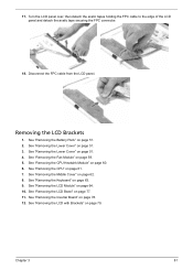
... CPU" on page 62. 8. See "Removing the Middle Cover" on page 61. 7. See "Removing the Inverter Board" on page 51. 2. Turn the LCD panel over, then detach the acetic tapes holding the FPC cable to the edge of the LCD panel and detach the acetic tape securing the FPC connector. ...the Fan Module" on page 77. 11. See "Removing the LCD with Brackets" on page 64. 10. See "Removing the LCD Module" on page 79. See "Removing the Keyboard" on page 51. 4. Removing the LCD Brackets 1. Chapter 3 81 See "Removing the Lower Cover" on page 63. 9. See "Removing the CPU Heatsink Module" ...
... CPU" on page 62. 8. See "Removing the Middle Cover" on page 61. 7. See "Removing the Inverter Board" on page 51. 2. Turn the LCD panel over, then detach the acetic tapes holding the FPC cable to the edge of the LCD panel and detach the acetic tape securing the FPC connector. ...the Fan Module" on page 77. 11. See "Removing the LCD with Brackets" on page 64. 10. See "Removing the LCD Module" on page 79. See "Removing the Keyboard" on page 51. 4. Removing the LCD Brackets 1. Chapter 3 81 See "Removing the Lower Cover" on page 63. 9. See "Removing the CPU Heatsink Module" ...
Service Guide
Page 72
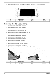
...Removing the Battery Pack" on page 62. 8. Remove the two screws (I) securing the left and right LCD brackets to remove the brackets. See "Removing the Middle Cover" on page 51. 2. See "Removing the LCD Brackets" on page 59. 5. See "Removing the Fan Module" on page 81. 14. Step 1~8 ...Size (Quantity) M2 x L3 (8) Color Silver Removing the LCD Module Hinges 1. See "Removing the Inverter Board" on...
...Removing the Battery Pack" on page 62. 8. Remove the two screws (I) securing the left and right LCD brackets to remove the brackets. See "Removing the Middle Cover" on page 51. 2. See "Removing the LCD Brackets" on page 59. 5. See "Removing the Fan Module" on page 81. 14. Step 1~8 ...Size (Quantity) M2 x L3 (8) Color Silver Removing the LCD Module Hinges 1. See "Removing the Inverter Board" on...
Service Guide
Page 89
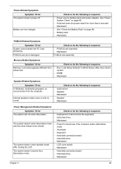
The system doesn't enter standby mode • after closing the LCD • The system doesn't resume from the keyboard) Hard disk drive Mainboard Press Fn+o and see if the computer enters hibernation mode. Power-Related Symptoms ... beeps every minute. Check or do the following in sequence Keyboard (if control is damaged. Touchpad Keyboard Hard disk connection board Hard disk drive Mainboard LCD cover switch Mainboard Hard disk connection board Hard disk drive Mainboard Chapter 4 99 Check or do the following in BIOS Setup Utility, then reboot system. Internal...
The system doesn't enter standby mode • after closing the LCD • The system doesn't resume from the keyboard) Hard disk drive Mainboard Press Fn+o and see if the computer enters hibernation mode. Power-Related Symptoms ... beeps every minute. Check or do the following in sequence Keyboard (if control is damaged. Touchpad Keyboard Hard disk connection board Hard disk drive Mainboard LCD cover switch Mainboard Hard disk connection board Hard disk drive Mainboard Chapter 4 99 Check or do the following in BIOS Setup Utility, then reboot system. Internal...
Service Guide
Page 90
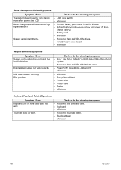
... Touchpad does not work correctly. Power Management-Related Symptoms Symptom / Error The system doesn't resume from standby mode after opening the LCD. System hangs intermittently. USB does not work . Check or do the following in sequence • Reconnect the keyboard cable. &#...Mainboard • Reconnect touchpad cable. • Touchpad board • Mainboard 100 Chapter 4 Check or do the following in sequence • LCD cover switch • Mainboard • Remove battery pack and let it cool for 2 hours. • Refresh battery (continue use battery until power...
... Touchpad does not work correctly. Power Management-Related Symptoms Symptom / Error The system doesn't resume from standby mode after opening the LCD. System hangs intermittently. USB does not work . Check or do the following in sequence • Reconnect the keyboard cable. &#...Mainboard • Reconnect touchpad cable. • Touchpad board • Mainboard 100 Chapter 4 Check or do the following in sequence • LCD cover switch • Mainboard • Remove battery pack and let it cool for 2 hours. • Refresh battery (continue use battery until power...


