
User Manual
Page 1
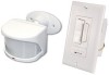
...operating instructions for switch locations. ( - All products work together. Heath®/Zenith wireless lighting controls are designed to a different code. Transmitter(s) and receiver(s) must have control which receiver(s) and set the code. Please read all instructional information and note any specific...NOT USE with fluorescent bulbs, appliances, power supplies, low voltage lighting, or any change to the following products: • Wireless Transmitters (Indoor / Outdoor) - 180° Motion Sensor - 240° Motion Sensor - See page 2 for a variety of remote controlled ...
...operating instructions for switch locations. ( - All products work together. Heath®/Zenith wireless lighting controls are designed to a different code. Transmitter(s) and receiver(s) must have control which receiver(s) and set the code. Please read all instructional information and note any specific...NOT USE with fluorescent bulbs, appliances, power supplies, low voltage lighting, or any change to the following products: • Wireless Transmitters (Indoor / Outdoor) - 180° Motion Sensor - 240° Motion Sensor - See page 2 for a variety of remote controlled ...

User Manual
Page 2
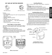
ON 1 2 3 4 Close-Up of Typical Code Switch (Factory Default Setting is Off) 2 598-1306-07 Code Switch Locations Code Switches DAY NIGHT NIGHT ONLY 1234 CODES DETECT 180° Motion Sensor Code Switches CODES DETECT 1 2 3 4 DAY NIGHT NIGHT ONLY 240° Motion Sensor CR2032 3 VOLTS ON 12 34 Code Switches Entry Switch Code Switches... WET LOCATION MADE IN CHINA Floodlight Code Switches ON Wall Switch Receiver Note: The "X" has been placed on the switches to help clarify the code settings on the previous page.
ON 1 2 3 4 Close-Up of Typical Code Switch (Factory Default Setting is Off) 2 598-1306-07 Code Switch Locations Code Switches DAY NIGHT NIGHT ONLY 1234 CODES DETECT 180° Motion Sensor Code Switches CODES DETECT 1 2 3 4 DAY NIGHT NIGHT ONLY 240° Motion Sensor CR2032 3 VOLTS ON 12 34 Code Switches Entry Switch Code Switches... WET LOCATION MADE IN CHINA Floodlight Code Switches ON Wall Switch Receiver Note: The "X" has been placed on the switches to help clarify the code settings on the previous page.
User Manual
Page 3
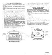
.... Detect Control Cover Screw Installing Batteries Before mounting motion sensor, remove battery compartment cover: • 180° Model - tree, post, house, etc.) using two screws provided. Install motion sensor to remove. To set the detection mode, remove battery compartment cover: &#...8226; 180° Model - ENGLISH 180° and 240° Motion Sensors 180° Motion Sensor 240° Motion Sensor Features: • No wiring required....
.... Detect Control Cover Screw Installing Batteries Before mounting motion sensor, remove battery compartment cover: • 180° Model - tree, post, house, etc.) using two screws provided. Install motion sensor to remove. To set the detection mode, remove battery compartment cover: &#...8226; 180° Model - ENGLISH 180° and 240° Motion Sensors 180° Motion Sensor 240° Motion Sensor Features: • No wiring required....
User Manual
Page 4
... where pets or traffic may trigger the control. • Nearby large, light colored objects reflecting light may result in front of motion sensor. Locate the RANGE control and ON-TIME control on after dusk (Off, 3 or 6 hours, until it opens. 1. Adjust Motion Sensor. Set the DETECT control switch to TEST mode. Adjust RANGE Control. Note...
... where pets or traffic may trigger the control. • Nearby large, light colored objects reflecting light may result in front of motion sensor. Locate the RANGE control and ON-TIME control on after dusk (Off, 3 or 6 hours, until it opens. 1. Adjust Motion Sensor. Set the DETECT control switch to TEST mode. Adjust RANGE Control. Note...

User Manual
Page 5
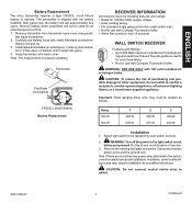
Motion Sensor Sensitivity 8 ft. (2.4 m) 240° 70 ft. (21 m) Maximum Range Maximum Coverage Angle 240° Motion Sensor Coverage Area Aim Sensor Down for Short Coverage Aim Sensor Higher for Long Coverage Adjusting Motion Sensor Coverage 598-1306-07 5 ENGLISH 8 ft. (2.4 m) 180° Motion Motion 70 ft. (21 m) Maximum Range Maximum Coverage Angle 180° Motion Sensor Coverage Area Sensor Least Sensitive Sensor Most Sensitive The detector is most sensitive to motion across its field of view.
Motion Sensor Sensitivity 8 ft. (2.4 m) 240° 70 ft. (21 m) Maximum Range Maximum Coverage Angle 240° Motion Sensor Coverage Area Aim Sensor Down for Short Coverage Aim Sensor Higher for Long Coverage Adjusting Motion Sensor Coverage 598-1306-07 5 ENGLISH 8 ft. (2.4 m) 180° Motion Motion 70 ft. (21 m) Maximum Range Maximum Coverage Angle 180° Motion Sensor Coverage Area Sensor Least Sensitive Sensor Most Sensitive The detector is most sensitive to motion across its field of view.

User Manual
Page 6
... magnet away from transmitter to complete the system. ScrewMounting:Attach transmitter back cover to door or window. Stick transmitter back cover to automatically turn the light on door or window (moving surface). Gently pull tab out of door or window in selected location and verify operation. Return magnet to original position... Mounting: Apply large piece of movement. The magnet should be in alignment (see Troubleshooting Guide. 4. Verify red LED on transmitter flashes momentarily and receiver turns light on transmitter flashes momentarily and receiver turns...
... magnet away from transmitter to complete the system. ScrewMounting:Attach transmitter back cover to door or window. Stick transmitter back cover to automatically turn the light on door or window (moving surface). Gently pull tab out of door or window in selected location and verify operation. Return magnet to original position... Mounting: Apply large piece of movement. The magnet should be in alignment (see Troubleshooting Guide. 4. Verify red LED on transmitter flashes momentarily and receiver turns light on transmitter flashes momentarily and receiver turns...
User Manual
Page 7
...to switch. 598-1306-07 7 Continued ENGLISH Battery Replacement The entry transmitter requires a type CR2032, 3-volt lithium battery to the light switch circuit before you proceed. Carefully pry battery loose with Compact Fluorescent bulbs. Install replacement battery in socket plus (+) side up ...period of overheating and possible damage to other equipment, do not install to control a receptacle, a motor-operated appliance, a fluorescent lighting fixture, or a transformer-supplied appliance. WARNING: Turn off the power to operate. Disconnect the two power wires and the ground...
...to switch. 598-1306-07 7 Continued ENGLISH Battery Replacement The entry transmitter requires a type CR2032, 3-volt lithium battery to the light switch circuit before you proceed. Carefully pry battery loose with Compact Fluorescent bulbs. Install replacement battery in socket plus (+) side up ...period of overheating and possible damage to other equipment, do not install to control a receptacle, a motor-operated appliance, a fluorescent lighting fixture, or a transformer-supplied appliance. WARNING: Turn off the power to operate. Disconnect the two power wires and the ground...

User Manual
Page 8
...9. You may need to bend the wires to the OFF (left side) position. The light should turn off and the receiver will once again accept a transmitter's ON/OFF commands. Note: DIM setting remembers last setting used to the wall box (see illustration). 6. Use the two wall switch screws (long...connectors to 90% brightness. 6. The light should turn on at your circuit breaker or fuse box. Push and release top of DIM button and release. Note: There are 5 DIM settings ranging from old switch. Set desired DIM level. Note: The DIM setting defaults to 50% in the junction box...
...9. You may need to bend the wires to the OFF (left side) position. The light should turn off and the receiver will once again accept a transmitter's ON/OFF commands. Note: DIM setting remembers last setting used to the wall box (see illustration). 6. Use the two wall switch screws (long...connectors to 90% brightness. 6. The light should turn on at your circuit breaker or fuse box. Push and release top of DIM button and release. Note: There are 5 DIM settings ranging from old switch. Set desired DIM level. Note: The DIM setting defaults to 50% in the junction box...

User Manual
Page 9
...used to hold the fixture while wiring. A signal will stay on full brightness. Note: Light will be sent to the receiver to turn the receiver ON or OFF. Set the LAMP MODE switch to the desired light turn -on then off at a combustible surface within 3 ft. (1 m). Secure with ...fire. Caution: To avoid water damage and electrical shock, keep lamp holders 30° below horizontal. 10. Manual Mode Flip the light switch off when motion is detected: • NORMAL or - Mounting Strap White to White Black to Black Rubber Plug Gasket Junction box ground wire to...
...used to hold the fixture while wiring. A signal will stay on full brightness. Note: Light will be sent to the receiver to turn the receiver ON or OFF. Set the LAMP MODE switch to the desired light turn -on then off at a combustible surface within 3 ft. (1 m). Secure with ...fire. Caution: To avoid water damage and electrical shock, keep lamp holders 30° below horizontal. 10. Manual Mode Flip the light switch off when motion is detected: • NORMAL or - Mounting Strap White to White Black to Black Rubber Plug Gasket Junction box ground wire to...

User Manual
Page 10
... receiver units. 4. Dip switches on transmitter and receiver units are being blocked, or transmitter is defective. 1. SOLUTION 1. Verify code settings on transmitter and receiver units do not match. 8. Box 90045 Bowling Green, KY 42102-9045 ATTN: Technical Service * If contacting ... 6. Switch on randomly. Same as 5, 6, and 7 above . 1. Device comes on device is required for 90 second initialization period (remote motion sensor). 5. Check for metal objects that could block the signal, or reposition the transmitter. 6. Check battery charge and replace if necessary. 7. ...
... receiver units. 4. Dip switches on transmitter and receiver units are being blocked, or transmitter is defective. 1. SOLUTION 1. Verify code settings on transmitter and receiver units do not match. 8. Box 90045 Bowling Green, KY 42102-9045 ATTN: Technical Service * If contacting ... 6. Switch on randomly. Same as 5, 6, and 7 above . 1. Device comes on device is required for 90 second initialization period (remote motion sensor). 5. Check for metal objects that could block the signal, or reposition the transmitter. 6. Check battery charge and replace if necessary. 7. ...

User Manual
Page 11
... the user's authority to province. HeathCo LLC reserves the right to discontinue products and to change specifications at no charge to misuse, abuse or negligence, light bulbs, batteries, and other equipment and components that a customer uses in its entirety. Repair service, adjustment and calibration due to you. Not Covered - REPAIR OR...
... the user's authority to province. HeathCo LLC reserves the right to discontinue products and to change specifications at no charge to misuse, abuse or negligence, light bulbs, batteries, and other equipment and components that a customer uses in its entirety. Repair service, adjustment and calibration due to you. Not Covered - REPAIR OR...