
Operating Guide
Page 3
...Specifications 55 Your Zenith Limited Warranty Back Cover Keep this manual with Monitor for future easy reference Table of Contents First step Setup and Operation Checklist 4 WARNINGS 5 Safety instructions 6 Monitor Overview Front Panel Controls 8 Connection Panel Overview 9 Remote Control Key Functions... 10 Accessories/Options 12 Using the Remote Control 13 Equipment Connections and Setup VCR Setup 14 Cable TV Setup 16 External AV Source ...
...Specifications 55 Your Zenith Limited Warranty Back Cover Keep this manual with Monitor for future easy reference Table of Contents First step Setup and Operation Checklist 4 WARNINGS 5 Safety instructions 6 Monitor Overview Front Panel Controls 8 Connection Panel Overview 9 Remote Control Key Functions... 10 Accessories/Options 12 Using the Remote Control 13 Equipment Connections and Setup VCR Setup 14 Cable TV Setup 16 External AV Source ...
Operating Guide
Page 4
... Setup See Table of Contents. 4 Turn video source equipment on . See page 29. (English is selected.) 6. Turn monitor on . 7. See page 11. 8. Install batteries in remote control. Choose on screen menu language. Fine-tune source image and sound to personal preference or as required by source. Connect all accessories. 2. See page...
... Setup See Table of Contents. 4 Turn video source equipment on . See page 29. (English is selected.) 6. Turn monitor on . 7. See page 11. 8. Install batteries in remote control. Choose on screen menu language. Fine-tune source image and sound to personal preference or as required by source. Connect all accessories. 2. See page...
Operating Guide
Page 8
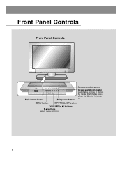
Front Panel Controls Front Panel Controls POWER ON OFF MENU VOL INPUT /I SELECT POWER ON OFF MENU Main Power button VOL INPUT /I SELECT Sub power button Remote control sensor Power standby indicator Illuminates orange in standby mode, illuminates green when the Monitor is turned on MENU button INPUT SELECT button VOLUME (F,G) buttons E,D buttons Select menu options. 8
Front Panel Controls Front Panel Controls POWER ON OFF MENU VOL INPUT /I SELECT POWER ON OFF MENU Main Power button VOL INPUT /I SELECT Sub power button Remote control sensor Power standby indicator Illuminates orange in standby mode, illuminates green when the Monitor is turned on MENU button INPUT SELECT button VOLUME (F,G) buttons E,D buttons Select menu options. 8
Operating Guide
Page 10
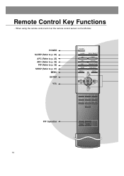
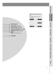
ZOOM+ 10 Remote Control Key Functions - POWER SLEEP (Refer to p. 24) APC (Refer to p. 25) ARC (Refer to p. 32) PIP (Refer to p. 36) SWAP (Refer to p. 37) MENU ENTER VOL PIP Operation POWER SLEEP APC ARC PIP SWAP MENU INPUT SELECT DASP PIP ARC TWIN PICTURE SUB INPUT MUTE VOL ENTER VOL 1 2 3 4 5 6 7 8 9 0 WIN.SIZE WIN.POSITION ZOOM- When using the remote control aim it at the remote control sensor on the Monitor.
ZOOM+ 10 Remote Control Key Functions - POWER SLEEP (Refer to p. 24) APC (Refer to p. 25) ARC (Refer to p. 32) PIP (Refer to p. 36) SWAP (Refer to p. 37) MENU ENTER VOL PIP Operation POWER SLEEP APC ARC PIP SWAP MENU INPUT SELECT DASP PIP ARC TWIN PICTURE SUB INPUT MUTE VOL ENTER VOL 1 2 3 4 5 6 7 8 9 0 WIN.SIZE WIN.POSITION ZOOM- When using the remote control aim it at the remote control sensor on the Monitor.
Operating Guide
Page 11
UP/DOWN Input Select Key on or off. RGB1 RGB2 COMPONENT S-VIDEO VIDEO Misc. 11 Safety Instructions Monitor Overview Connections Basic Operation Sleep Timer Picture & Sound Special Features INPUT SELECT DASP (Refer to p. 27) PIP ARC (Refer to p. 36) TWIN PICTURE (Refer to p. 39) SUB INPUT (Refer to p. 39) MUTE switches the sound on remote control Each press changes the source as shown below.
UP/DOWN Input Select Key on or off. RGB1 RGB2 COMPONENT S-VIDEO VIDEO Misc. 11 Safety Instructions Monitor Overview Connections Basic Operation Sleep Timer Picture & Sound Special Features INPUT SELECT DASP (Refer to p. 27) PIP ARC (Refer to p. 36) TWIN PICTURE (Refer to p. 39) SUB INPUT (Refer to p. 39) MUTE switches the sound on remote control Each press changes the source as shown below.

Operating Guide
Page 12
Accessories/Options Accessories POWER SLEEP APC ARC PIP SWAP MENU INPUT SELECT DASP PIP ARC TWIN PICTURE SUB INPUT MUTE VOL ENTER VOL 1 2 3 4 5 6 7 8 9 0 WIN.SIZE WIN.POSITION ZOOM- ZOOM+ Remote Control Owner's Manual 1.5V 1.5V Power Cord Alkaline Batteries PC Audio Cable D-sub 15 pin cable Video Cable DVI Computer (DVI-D) Cable Speaker cable Options Speakers 12
Accessories/Options Accessories POWER SLEEP APC ARC PIP SWAP MENU INPUT SELECT DASP PIP ARC TWIN PICTURE SUB INPUT MUTE VOL ENTER VOL 1 2 3 4 5 6 7 8 9 0 WIN.SIZE WIN.POSITION ZOOM- ZOOM+ Remote Control Owner's Manual 1.5V 1.5V Power Cord Alkaline Batteries PC Audio Cable D-sub 15 pin cable Video Cable DVI Computer (DVI-D) Cable Speaker cable Options Speakers 12
Operating Guide
Page 13
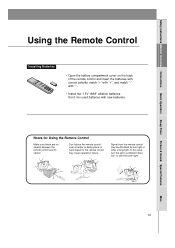
..., match "+" with "+", and match "-" with new batteries. Misc. 13 Notes for Using the Remote Control Make sure these are no objects between the remote control and its sensor. Signal from the remote control may cause operation failure. A hard impact to a different direction, or dim the room light.... Don't mix used batteries with "-". • Install two 1.5V "AAA" alkaline batteries. Don't place the remote control near a heater or damp place. In this case, turn the set to the remote control may be disturbed by sun light or other strong light.
..., match "+" with "+", and match "-" with new batteries. Misc. 13 Notes for Using the Remote Control Make sure these are no objects between the remote control and its sensor. Signal from the remote control may cause operation failure. A hard impact to a different direction, or dim the room light.... Don't mix used batteries with "-". • Install two 1.5V "AAA" alkaline batteries. Don't place the remote control near a heater or damp place. In this case, turn the set to the remote control may be disturbed by sun light or other strong light.
Operating Guide
Page 15
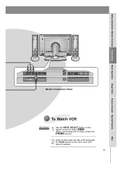
... 232C INPUT (DIGITAL RGB INPUT) (PC/DTV INPUT) (CONTROL/SERVICE) Monitor Connections Panel To Watch VCR 1 INPUT SELECT Use the INPUT SELECT button on the remote control to select VIDEO. (When connecting with S-Video, select the S-VIDEO source.) 2 Insert a video tape into the VCR and press the PLAY button on the...
... 232C INPUT (DIGITAL RGB INPUT) (PC/DTV INPUT) (CONTROL/SERVICE) Monitor Connections Panel To Watch VCR 1 INPUT SELECT Use the INPUT SELECT button on the remote control to select VIDEO. (When connecting with S-Video, select the S-VIDEO source.) 2 Insert a video tape into the VCR and press the PLAY button on the...

Operating Guide
Page 16
...) Monitor Connections Panel (R) AUDIO (L) VIDEO TV VCR RF Cable Cable Box Connections Panel To Watch Cable TV Programming 1 Use the INPUT SELECT button on the remote control to cable service provided channels using the cable box. Cable TV Setup - After subscribing to a cable TV service from a local provider and installing a converter...
...) Monitor Connections Panel (R) AUDIO (L) VIDEO TV VCR RF Cable Cable Box Connections Panel To Watch Cable TV Programming 1 Use the INPUT SELECT button on the remote control to cable service provided channels using the cable box. Cable TV Setup - After subscribing to a cable TV service from a local provider and installing a converter...
Operating Guide
Page 17
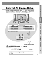
.../SERVICE) R AUDIO L VIDEO Connections Panel Camcorder Video Game Player DDR Typical External Equipment To watch external AV source 1 Use the INPUT SELECT on the monitor remote control to an external source, match the colors of AV input jacks on the Monitor with the output jacks on the audio/video equipment: Video...
.../SERVICE) R AUDIO L VIDEO Connections Panel Camcorder Video Game Player DDR Typical External Equipment To watch external AV source 1 Use the INPUT SELECT on the monitor remote control to an external source, match the colors of AV input jacks on the Monitor with the output jacks on the audio/video equipment: Video...
Operating Guide
Page 18
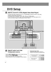
... monitor and audio outputs to Audio jacks of DVD player Y PB PR Y Pb Pr Y B-Y R-Y Y Cb Cr Y PB PR 18 Component input jacks on the monitor's remote control to Monitor's Component input jacks as indicated below. DC OUTPUT (DC 12V) R AUDIO L MONO AV INPUT VIDEO S-VIDEO Y PB PR COMPONENT (DVD/DTV INPUT...
... monitor and audio outputs to Audio jacks of DVD player Y PB PR Y Pb Pr Y B-Y R-Y Y Cb Cr Y PB PR 18 Component input jacks on the monitor's remote control to Monitor's Component input jacks as indicated below. DC OUTPUT (DC 12V) R AUDIO L MONO AV INPUT VIDEO S-VIDEO Y PB PR COMPONENT (DVD/DTV INPUT...
Operating Guide
Page 19
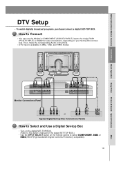
... • You can use the Monitor's COMPONENT (DVD/DTV INPUT) inputs, the single RGB1 (PC/DTV INPUT) or RGB2 for video connections, depending on the remote control to the owner's manual for the digital SET-TOP BOX.) • Use the INPUT SELECT button on your Set-top Box connectors. Safety Instructions...
... • You can use the Monitor's COMPONENT (DVD/DTV INPUT) inputs, the single RGB1 (PC/DTV INPUT) or RGB2 for video connections, depending on the remote control to the owner's manual for the digital SET-TOP BOX.) • Use the INPUT SELECT button on your Set-top Box connectors. Safety Instructions...

Operating Guide
Page 20
.... • An image is not visible if the resolution is set up this monitor in your PC is 1280X768. use INPUT SELECT On the remote control PC Setup • First, turn on the display by pressing the button on the Monitor or by pressing the POWER button on the Monitor...connect the LCD monitor to use a screen saver when possible. • Change the output resolution of time. Tips • Avoid keeping a fixed image on the remote control to select the RGB1 input source. • Set the resolution output of the PC to SXGA or under (1280 x 1024, 75Hz). The fixed image...
.... • An image is not visible if the resolution is set up this monitor in your PC is 1280X768. use INPUT SELECT On the remote control PC Setup • First, turn on the display by pressing the button on the Monitor or by pressing the POWER button on the Monitor...connect the LCD monitor to use a screen saver when possible. • Change the output resolution of time. Tips • Avoid keeping a fixed image on the remote control to select the RGB1 input source. • Set the resolution output of the PC to SXGA or under (1280 x 1024, 75Hz). The fixed image...

Operating Guide
Page 22
... this moment, the Monitor is switched to turn the Monitor on the Monitor. When using the remote control, aim it on. 3 If the Monitor is turned off with the ON OFF button ...on the Monitor • Press the main ON OFF button on the Monitor to turn the Monitor on the remote control to standby mode. Turning on the Monitor just after installation 1 Connect power cord correctly. 2 Press the...the Monitor (power cord is still connected) 1 If the Monitor is turned off with the remote control button. • Press the or INPUT SELECT button on the Monitor or press the POWER or INPUT...
... this moment, the Monitor is switched to turn the Monitor on the Monitor. When using the remote control, aim it on. 3 If the Monitor is turned off with the ON OFF button ...on the Monitor • Press the main ON OFF button on the Monitor to turn the Monitor on the remote control to standby mode. Turning on the Monitor just after installation 1 Connect power cord correctly. 2 Press the...the Monitor (power cord is still connected) 1 If the Monitor is turned off with the remote control button. • Press the or INPUT SELECT button on the Monitor or press the POWER or INPUT...

Operating Guide
Page 23
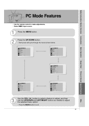
... ADJ. Auto. Safety Instructions Monitor Overview Connections Basic Operation Sleep Timer Picture & Sound Special Features Checking Available Features - Size Win. Position Win. Config. Use the remote control to exit. 23 Misc. ARC(Main) Zoom In/Out Position Clock Adjust Phase Adjust Reset D Move menu Exit E 3 Use the VOL ( G ) button to select...
... ADJ. Auto. Safety Instructions Monitor Overview Connections Basic Operation Sleep Timer Picture & Sound Special Features Checking Available Features - Size Win. Position Win. Config. Use the remote control to exit. 23 Misc. ARC(Main) Zoom In/Out Position Clock Adjust Phase Adjust Reset D Move menu Exit E 3 Use the VOL ( G ) button to select...
Operating Guide
Page 41
... adjustments. - R-Adjust G-Adjust B-Adjust Screen Saver Set ID D Move menu Exit E TWIN/PIP Twin PIP Input (Main) Input (Sub) Win. Config. Position Win. Use the remote control to exit. 41 Misc. Select RGB 1 input source. 1 Press the MENU button. 2 Press the UP/DOWN button. • Each press will cycle through the...
... adjustments. - R-Adjust G-Adjust B-Adjust Screen Saver Set ID D Move menu Exit E TWIN/PIP Twin PIP Input (Main) Input (Sub) Win. Config. Position Win. Use the remote control to exit. 41 Misc. Select RGB 1 input source. 1 Press the MENU button. 2 Press the UP/DOWN button. • Each press will cycle through the...

Operating Guide
Page 46
...) 4 DTR (DTE side ready) 5 GND 6 DSR (DCE side ready) 9 7 RTS (Ready to send) 6 8 CTS (Clear to control the Monitor's functions with an external control device. remote control k lock mode 14. Balance k 20. Power k 02. Color k 10. Treble k 18. Volume Mute k 06. Sharpness k 12. Type of Connector: D-Sub 9-pin Male 1 No. Brightness...
...) 4 DTR (DTE side ready) 5 GND 6 DSR (DCE side ready) 9 7 RTS (Ready to send) 6 8 CTS (Clear to control the Monitor's functions with an external control device. remote control k lock mode 14. Balance k 20. Power k 02. Color k 10. Treble k 18. Volume Mute k 06. Sharpness k 12. Type of Connector: D-Sub 9-pin Male 1 No. Brightness...
Operating Guide
Page 47
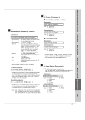
... control LCD set is data read status of command. OK Acknowledgement [Command2][ ][Set ID][ ][OK][Data][x] * The Monitor transmits ACK (acknowledgement) based on the Monitor's remote control. Select '0', factory adjustment. (* Transmit as Hexadecimal code.) To transmit command data. Power (Command:a) G To control Power On/Off of the PC computer. Transmit 'FF...
... control LCD set is data read status of command. OK Acknowledgement [Command2][ ][Set ID][ ][OK][Data][x] * The Monitor transmits ACK (acknowledgement) based on the Monitor's remote control. Select '0', factory adjustment. (* Transmit as Hexadecimal code.) To transmit command data. Power (Command:a) G To control Power On/Off of the PC computer. Transmit 'FF...
Operating Guide
Page 48
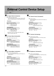
...0 ~ Max : 64 * Transmit as Hexadecimal code. You can also adjust mute using the ARC button on remote control or in the Picture menu. You can also adjust volume with the VOL buttons on remote control. Transmission [k][c][ ][Set ID][ ][Data][Cr] Data 0 : Wide screen (16:9) 1 : Normal screen...64 07. Acknowledgement [h][ ][Set ID][ ][OK][Data][X] Data Min : 0 ~ Max : 64 You can also adjust the screen format using the MUTE button on remote control. You can also adjust brightness in the Picture menu. Transmission [k][h][ ][Set ID][ ][Data][Cr] Data Min : 0 ~ Max : 64 * Transmit as...
...0 ~ Max : 64 * Transmit as Hexadecimal code. You can also adjust mute using the ARC button on remote control or in the Picture menu. You can also adjust volume with the VOL buttons on remote control. Transmission [k][c][ ][Set ID][ ][Data][Cr] Data 0 : Wide screen (16:9) 1 : Normal screen...64 07. Acknowledgement [h][ ][Set ID][ ][OK][Data][X] Data Min : 0 ~ Max : 64 You can also adjust the screen format using the MUTE button on remote control. You can also adjust brightness in the Picture menu. Transmission [k][h][ ][Set ID][ ][Data][Cr] Data Min : 0 ~ Max : 64 * Transmit as...

Operating Guide
Page 49
.... OSD Select (Command:l) G To select OSD (On Screen Display) on/off , the remote control will not operate the unit. 14. Remote Control Lock Mode (Command:m) G To set up the locking function of LCD remote control. Transmission [k][i][ ][Set ID][ ][Data][Cr] Data Min : 0 ~ Max : 64... off 1 : PIP 2 : Twin picture (DW1) 3 : Twin picture (DW2) Acknowledgement [n][ ][Set ID][ ][OK][Data][X] Data 0 : PIP/ DW off 1 : OSD on remote control or in the Picture menu. 09. Transmission [k][k][ ][Set ID][ ][Data][Cr] Data Min : 0 ~ Max : 64 * Transmit as Hexadecimal code. You can also adjust tint...
.... OSD Select (Command:l) G To select OSD (On Screen Display) on/off , the remote control will not operate the unit. 14. Remote Control Lock Mode (Command:m) G To set up the locking function of LCD remote control. Transmission [k][i][ ][Set ID][ ][Data][Cr] Data Min : 0 ~ Max : 64... off 1 : PIP 2 : Twin picture (DW1) 3 : Twin picture (DW2) Acknowledgement [n][ ][Set ID][ ][OK][Data][X] Data 0 : PIP/ DW off 1 : OSD on remote control or in the Picture menu. 09. Transmission [k][k][ ][Set ID][ ][Data][Cr] Data Min : 0 ~ Max : 64 * Transmit as Hexadecimal code. You can also adjust tint...