

Operating Guide
Page 1
Installation, Setup & Operating Guide I Warranty Model Number | L15V26D | LCD-TV / Monitor © Copyright 2004, LG Electronics USA, Inc.
Installation, Setup & Operating Guide I Warranty Model Number | L15V26D | LCD-TV / Monitor © Copyright 2004, LG Electronics USA, Inc.

Operating Guide
Page 2
.... NOTE TO CABLE/TV INSTALLER: This reminder is encouraged to try to correct the interference by LG Electronics U.S.A., Inc. 1000 Sylvan Avenue, Englewood Cliffs, NJ 07632 http://www.zenith.com 2 These limits are located on a circuit different from Zenith Electronics Corporation. Any ...equilateral triangle, is intended to alert the user to the presence of uninsulated "dangerous voltage" within an equilateral triangle is : Zenith Electronics Corporation 1-201-816-2000 Marked and Distributed in a particular installation. NO USER SERVICEABLE PARTS INSIDE. COMPLIANCE: The responsible ...
.... NOTE TO CABLE/TV INSTALLER: This reminder is encouraged to try to correct the interference by LG Electronics U.S.A., Inc. 1000 Sylvan Avenue, Englewood Cliffs, NJ 07632 http://www.zenith.com 2 These limits are located on a circuit different from Zenith Electronics Corporation. Any ...equilateral triangle, is intended to alert the user to the presence of uninsulated "dangerous voltage" within an equilateral triangle is : Zenith Electronics Corporation 1-201-816-2000 Marked and Distributed in a particular installation. NO USER SERVICEABLE PARTS INSIDE. COMPLIANCE: The responsible ...

Operating Guide
Page 5
... DVD Player Connections 17 DTV (Set-top box) Connections 18 PC/Computer Connections 19 PC Mode Functions Check 21 3 Turning the TV On 22 TV Mode Menus 23 Menu Language Selection 24 Auto Programming: Finding/Erasing channels 25 Favorite Channel Memory 27 4 Clock Setup 28 Off Timer...Setup 35 Closed Captions 41 6 Parental Control 44 Auto Off 47 Key lock 48 7 Maintenance Product Specifications Troubleshooting CheckList Your Zenith Limited Warranty 49 50 51 Back cover 5 MISC. SPECIAL FEATURES VIDEO / AUDIO CLOCK/ TIMERS BASIC FEATURES INSTALLATION INTRODUCTION
... DVD Player Connections 17 DTV (Set-top box) Connections 18 PC/Computer Connections 19 PC Mode Functions Check 21 3 Turning the TV On 22 TV Mode Menus 23 Menu Language Selection 24 Auto Programming: Finding/Erasing channels 25 Favorite Channel Memory 27 4 Clock Setup 28 Off Timer...Setup 35 Closed Captions 41 6 Parental Control 44 Auto Off 47 Key lock 48 7 Maintenance Product Specifications Troubleshooting CheckList Your Zenith Limited Warranty 49 50 51 Back cover 5 MISC. SPECIAL FEATURES VIDEO / AUDIO CLOCK/ TIMERS BASIC FEATURES INSTALLATION INTRODUCTION

Operating Guide
Page 6
On/Off Button on . Controls Front of the TV Side Control Panel ch vol enter menu tv/video Channel Buttons Volume Buttons Enter Button Menu Button TV/Video Button Remote Control Sensor Power/Standby indicator Illuminates red in standby mode, Illuminates green when the TV is turned on /off 6
On/Off Button on . Controls Front of the TV Side Control Panel ch vol enter menu tv/video Channel Buttons Volume Buttons Enter Button Menu Button TV/Video Button Remote Control Sensor Power/Standby indicator Illuminates red in standby mode, Illuminates green when the TV is turned on /off 6

Operating Guide
Page 7
Never attempt to operate the S-Video Input Headphone Jack Audio/Video Input TV on AC power. This TV operates on DC power. INTRODUCTION Back of the TV Connection Panel AC INPUT Y PB PR COMPONENT(480i/480p/720p/1080i) DVD/DTV IN H/P S-VIDEO VIDEO(MONO) L AUDIO R VIDEO IN PC INPUT ANT IN +75 Ω PC SOUND Power Cord Socket - DVD/DTV IN (Component (480i, 480p,720p,1080i) Input PC Input PC Sound Antenna Input 7
Never attempt to operate the S-Video Input Headphone Jack Audio/Video Input TV on AC power. This TV operates on DC power. INTRODUCTION Back of the TV Connection Panel AC INPUT Y PB PR COMPONENT(480i/480p/720p/1080i) DVD/DTV IN H/P S-VIDEO VIDEO(MONO) L AUDIO R VIDEO IN PC INPUT ANT IN +75 Ω PC SOUND Power Cord Socket - DVD/DTV IN (Component (480i, 480p,720p,1080i) Input PC Input PC Sound Antenna Input 7

Operating Guide
Page 8
Controls Remote Control Buttons POWER NUMBERS PAGE 32 APC MENU PAGE 39 CHANNEL (DE) MTS PAGE 27 PAGE 25 FCR AUTO PROGRAM q Press the FLASHBK button to view the last program you were watching. power tv/video 1 2 3 4 5 6 7 8 9 apc cc 0 menu mute ch vol enter vol mts ch sleep fcr flashbk dasp a.prog memory/erase 8
Controls Remote Control Buttons POWER NUMBERS PAGE 32 APC MENU PAGE 39 CHANNEL (DE) MTS PAGE 27 PAGE 25 FCR AUTO PROGRAM q Press the FLASHBK button to view the last program you were watching. power tv/video 1 2 3 4 5 6 7 8 9 apc cc 0 menu mute ch vol enter vol mts ch sleep fcr flashbk dasp a.prog memory/erase 8
Operating Guide
Page 9
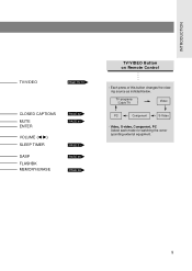
TV programs /Cable TV Video PC Component S-Video - Video, S-video, Component, PC Select each mode for watching the corresponding external equipment. 9 Each press of this button changes the viewing source as indicted below. INTRODUCTION TV/VIDEO PAGE 15~19 CLOSED CAPTIONS MUTE ENTER VOLUME (F G) SLEEP TIMER DASP FLASHBK MEMORY/ERASE PAGE 42 PAGE 40 PAGE 31 PAGE 35 PAGE 26 TV/VIDEO Button on Remote Control -
TV programs /Cable TV Video PC Component S-Video - Video, S-video, Component, PC Select each mode for watching the corresponding external equipment. 9 Each press of this button changes the viewing source as indicted below. INTRODUCTION TV/VIDEO PAGE 15~19 CLOSED CAPTIONS MUTE ENTER VOLUME (F G) SLEEP TIMER DASP FLASHBK MEMORY/ERASE PAGE 42 PAGE 40 PAGE 31 PAGE 35 PAGE 26 TV/VIDEO Button on Remote Control -
Operating Guide
Page 10
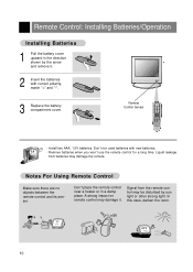
... . 2 Insert the batteries with new batteries. - Remote Control: Installing Batteries/Operation Installing Batteries 1 Pull the battery cover upward in a damp place. Remote Control Sensor power tv/video 1 2 3 4 5 6 7 8 9 apc cc 0 menu mute ch vol enter vol mts ch sleep fcr flashbk dasp a.prog memory/erase -
... . 2 Insert the batteries with new batteries. - Remote Control: Installing Batteries/Operation Installing Batteries 1 Pull the battery cover upward in a damp place. Remote Control Sensor power tv/video 1 2 3 4 5 6 7 8 9 apc cc 0 menu mute ch vol enter vol mts ch sleep fcr flashbk dasp a.prog memory/erase -

Operating Guide
Page 11
VESA standard mounting interface - If you intend to mount the TV to a wall, attach this plate to the back of the TV. 11 INTRODUCTION TV Overview Accessories power tv/video 1 2 3 4 5 6 7 8 9 apc cc 0 menu mute ch vol enter vol mts ch sleep fcr flashbk dasp a.prog memory/erase Remote control 1.5V 1.5V AAA Batteries Operating guide Power cord PC signal cable PC sound cable Tie bands - Arrange the wires with the tie band.
VESA standard mounting interface - If you intend to mount the TV to a wall, attach this plate to the back of the TV. 11 INTRODUCTION TV Overview Accessories power tv/video 1 2 3 4 5 6 7 8 9 apc cc 0 menu mute ch vol enter vol mts ch sleep fcr flashbk dasp a.prog memory/erase Remote control 1.5V 1.5V AAA Batteries Operating guide Power cord PC signal cable PC sound cable Tie bands - Arrange the wires with the tie band.
Operating Guide
Page 12
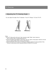
... touching the LCD screen or holding your finger(s) against it for long periods of the TV between -3° and 15° (Range: -3°±3 and 15°±3º). -3° 15° Notes q If the TV feels cold to the touch, there may be a small "flicker" when turned on the... screen. 12 This is normal, there is nothing wrong with TV. However, this will have no adverse effect on the screen, like red, green or blue spots. TV Overview Adjusting the TV Viewing Angle - q Some dot defects may produce some temporary distortion effects on . Doing so...
... touching the LCD screen or holding your finger(s) against it for long periods of the TV between -3° and 15° (Range: -3°±3 and 15°±3º). -3° 15° Notes q If the TV feels cold to the touch, there may be a small "flicker" when turned on the... screen. 12 This is normal, there is nothing wrong with TV. However, this will have no adverse effect on the screen, like red, green or blue spots. TV Overview Adjusting the TV Viewing Angle - q Some dot defects may produce some temporary distortion effects on . Doing so...

Operating Guide
Page 13
...wire. Connecting to the right. - If antenna is commonly used in single family dwellings. VHF Antenna Turn clockwise to the antenna jack on the TV. - In poor signal areas, to get better picture quality, install the antenna as shown below. (Use the correct type of wall antenna jack.)... used in apartment buildings, connect the antenna cable as shown to an Outdoor Antenna Setup q This type of antenna is split for two TVs, use signal splitter for the type of antenna cable for connection. UHF Antenna Single Family Home 75Ω Round Cable Bronze Wire 300Ω...
...wire. Connecting to the right. - If antenna is commonly used in single family dwellings. VHF Antenna Turn clockwise to the antenna jack on the TV. - In poor signal areas, to get better picture quality, install the antenna as shown below. (Use the correct type of wall antenna jack.)... used in apartment buildings, connect the antenna cable as shown to an Outdoor Antenna Setup q This type of antenna is split for two TVs, use signal splitter for the type of antenna cable for connection. UHF Antenna Single Family Home 75Ω Round Cable Bronze Wire 300Ω...
Operating Guide
Page 14
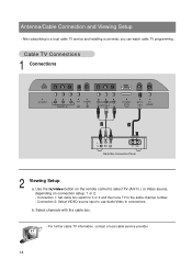
..., depending on the remote control to a local cable TV service and installing a converter, you can watch cable TV programming. For further cable TV information, contact a local cable service provider. 14 Use the tv/video button on connection setup: 1 or 2. - Select channels with the cable box. - Cable TV Connections 1 Connections AC INPUT Y PB PR H/P S-VIDEO COMPONENT...
..., depending on the remote control to a local cable TV service and installing a converter, you can watch cable TV programming. For further cable TV information, contact a local cable service provider. 14 Use the tv/video button on connection setup: 1 or 2. - Select channels with the cable box. - Cable TV Connections 1 Connections AC INPUT Y PB PR H/P S-VIDEO COMPONENT...

Operating Guide
Page 15
... connection ANT OUT S-VIDEO OUT CH3 IN CH4 (R) AUDIO(L) VIDEO VCR Connection Panel 2 Viewing Setup Watching TV programs Turn the TV on VCR to use Audio/Video In connections. In Video mode, TV automatically reverts to a channel. Connecting a VCR 1 Connections q Connect the audio/video output jacks on and...jacks on connection setup: 1 or 2. - Watching VCR a. Connection 1: Set VCR switch to 3 or 4 and then tune TV to select TV (Ant In.) or Video source, depending on the TV. b. VCR Connection and Viewing Setup - Insert a video tape into the VCR and press the PLAY button. 15 Use...
... connection ANT OUT S-VIDEO OUT CH3 IN CH4 (R) AUDIO(L) VIDEO VCR Connection Panel 2 Viewing Setup Watching TV programs Turn the TV on VCR to use Audio/Video In connections. In Video mode, TV automatically reverts to a channel. Connecting a VCR 1 Connections q Connect the audio/video output jacks on and...jacks on connection setup: 1 or 2. - Watching VCR a. Connection 1: Set VCR switch to 3 or 4 and then tune TV to select TV (Ant In.) or Video source, depending on the TV. b. VCR Connection and Viewing Setup - Insert a video tape into the VCR and press the PLAY button. 15 Use...
Operating Guide
Page 16
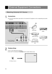
tv/video Video On Remote Control 16 S-VIDEO VIDEO(MONO) L AUDIO R VIDEO IN PC INPUT ANT IN +75 Ω PC SOUND TV Connection Panel Camcorder CDGP External Equipment Connection Panel R AUDIO L VIDEO Video Game set CDI VCDP 2 Viewing Setup q Turn on the external A/V equipment. q Turn the TV on and use the tv/video button to the corresponding input jacks on the TV. External Equipment Connections Watching External A/V Source 1 Connections q Connect the audio/video output jacks on the external A/V equipment to select Video source.
tv/video Video On Remote Control 16 S-VIDEO VIDEO(MONO) L AUDIO R VIDEO IN PC INPUT ANT IN +75 Ω PC SOUND TV Connection Panel Camcorder CDGP External Equipment Connection Panel R AUDIO L VIDEO Video Game set CDI VCDP 2 Viewing Setup q Turn on the external A/V equipment. q Turn the TV on and use the tv/video button to the corresponding input jacks on the TV. External Equipment Connections Watching External A/V Source 1 Connections q Connect the audio/video output jacks on the external A/V equipment to select Video source.
Operating Guide
Page 17
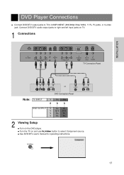
...720p/1080i) DVD/DTV IN VIDEO(MONO) L AUDIO R VIDEO IN PC INPUL T ANT IN +75 Ω PC SOUND TV Connection Panel INSTALLATION Y PB PR (R) AUDIO (L) or S-VIDEO (R) AUDIO (L) Note: TV INPUT DVD Connection Panel Y PB PR DVD OUTPUT Y Y Y Y Cb Cr B-Y R-Y Pb Pr PB PR 2 Viewing Setup... q Turn on and use tv/video button to select Component source. q See DVD/DTV user's manual for operating instructions. Connect DVD/DTV audio output jacks to TV's COMPONENT (480i/480p/720p/1080i), Y, PB, PR jacks, or S-video jack. q Turn ...
...720p/1080i) DVD/DTV IN VIDEO(MONO) L AUDIO R VIDEO IN PC INPUL T ANT IN +75 Ω PC SOUND TV Connection Panel INSTALLATION Y PB PR (R) AUDIO (L) or S-VIDEO (R) AUDIO (L) Note: TV INPUT DVD Connection Panel Y PB PR DVD OUTPUT Y Y Y Y Cb Cr B-Y R-Y Pb Pr PB PR 2 Viewing Setup... q Turn on and use tv/video button to select Component source. q See DVD/DTV user's manual for operating instructions. Connect DVD/DTV audio output jacks to TV's COMPONENT (480i/480p/720p/1080i), Y, PB, PR jacks, or S-video jack. q Turn ...
Operating Guide
Page 18
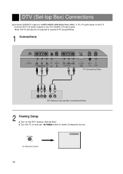
Connect DTV L/R audio outputs to COMPONENT(480i/480p/720p/1080i), Y, PB, PR jack inputs on the TV. q Turn the TV on the DTV receiver (Set-top Box). tv/video Component On Remote Control 18 Note: A DTV set-top box is required to receive DTV programming. 1 Connections AC INPUT Y PB PR ...VIDEO(MONO) L AUDIO R VIDEO IN PC INPUL T ANT IN +75 Ω PC SOUND TV Connections Panel Y PB PR (R) AUDIO (L) DTV Receiver (Set-top Box) Connections Panel 2 Viewing Setup q Turn on and use tv/video button to select Component source. DTV (Set-top Box) Connections q Connect DVD/DTV output ...
Connect DTV L/R audio outputs to COMPONENT(480i/480p/720p/1080i), Y, PB, PR jack inputs on the TV. q Turn the TV on the DTV receiver (Set-top Box). tv/video Component On Remote Control 18 Note: A DTV set-top box is required to receive DTV programming. 1 Connections AC INPUT Y PB PR ...VIDEO(MONO) L AUDIO R VIDEO IN PC INPUL T ANT IN +75 Ω PC SOUND TV Connections Panel Y PB PR (R) AUDIO (L) DTV Receiver (Set-top Box) Connections Panel 2 Viewing Setup q Turn on and use tv/video button to select Component source. DTV (Set-top Box) Connections q Connect DVD/DTV output ...

Operating Guide
Page 19
... +75 Ω PC SOUND PC Connections Panel 2 Viewing Setup q Turn on and use tv/video button to the PC with the PC cable. PC tv/video On Remote Control 19 q Connect the PC audio output to the TV. q Turn the TV on the PC/Computer. See the next page. After setup, be sure to... select RGB-PC to see the PC image on TV screen. 1 Connections q Set the monitor output resolution...
... +75 Ω PC SOUND PC Connections Panel 2 Viewing Setup q Turn on and use tv/video button to the PC with the PC cable. PC tv/video On Remote Control 19 q Connect the PC audio output to the TV. q Turn the TV on the PC/Computer. See the next page. After setup, be sure to... select RGB-PC to see the PC image on TV screen. 1 Connections q Set the monitor output resolution...
Operating Guide
Page 20
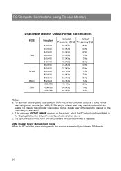
... switches to DPM mode. 20 c. DPM (Display Power Management) mode When the PC is separate. b. The synchronization input form for the computer you are using TV as a Monitor) Displayable Monitor Output Format Specifications MODE VGA SVGA (MAC) XGA Resolution 640x400 640x480 640x480 640x480 640x480 640x480 800x600 800x600 800x600 800x600 800x600 832x624...
... switches to DPM mode. 20 c. DPM (Display Power Management) mode When the PC is separate. b. The synchronization input form for the computer you are using TV as a Monitor) Displayable Monitor Output Format Specifications MODE VGA SVGA (MAC) XGA Resolution 640x400 640x480 640x480 640x480 640x480 640x480 800x600 800x600 800x600 800x600 800x600 832x624...

Operating Guide
Page 21
... ranges of H-Position is -100~+100. (Based on the input mode, the adjustment range may change.) q Phase Remove any vertical bars or stripes appearing on TV screen. 1 Use the menu button to the default settings programmed at the factory; The adjustment range is in progress.) q Reset Returns to display the available...
... ranges of H-Position is -100~+100. (Based on the input mode, the adjustment range may change.) q Phase Remove any vertical bars or stripes appearing on TV screen. 1 Use the menu button to the default settings programmed at the factory; The adjustment range is in progress.) q Reset Returns to display the available...

Operating Guide
Page 22
...to receive channels in your local broadcast area. 3 After viewing, press the power button on the remote control or on/off on the TV side panel to turn the TV on vacation, disconnect the power plug from the wall power outlet. 22 q Volume (G) button increases the sound level. q Volume (F) ...button decreases the sound level. At this moment, the TV is switched to standby mode. q Note: See page 25 if you will be away on . 2 Use the channel (D,E) or number buttons to select a ...
...to receive channels in your local broadcast area. 3 After viewing, press the power button on the remote control or on/off on the TV side panel to turn the TV on vacation, disconnect the power plug from the wall power outlet. 22 q Volume (G) button increases the sound level. q Volume (F) ...button decreases the sound level. At this moment, the TV is switched to standby mode. q Note: See page 25 if you will be away on . 2 Use the channel (D,E) or number buttons to select a ...


