Owner's Manual
Page 4
...loud popular music passages can be reached easily. • Secure placement or installation is faulty. • Install this unit, reduce the volume level. YAMAHA shall not be sure to avoid condensation inside the unit rises, it may cause fire, damage to the unit and/or personal injury. • ... being damaged. • If you hear distorted noise (i.e., unnatural, intermittent "rapping" or "hammering" sounds) coming from the rear panel. CAUTION: Read this YAMAHA subwoofer system. YAMAHA will radiate from this unit near the YST port of the unit to prevent fire or damage.
...loud popular music passages can be reached easily. • Secure placement or installation is faulty. • Install this unit, reduce the volume level. YAMAHA shall not be sure to avoid condensation inside the unit rises, it may cause fire, damage to the unit and/or personal injury. • ... being damaged. • If you hear distorted noise (i.e., unnatural, intermittent "rapping" or "hammering" sounds) coming from the rear panel. CAUTION: Read this YAMAHA subwoofer system. YAMAHA will radiate from this unit near the YST port of the unit to prevent fire or damage.
Owner's Manual
Page 5
... not correspond with the coloured markings identifying the terminals in the subwoofer to the AC outlet 8 CONTROLS AND THEIR FUNCTIONS 9 AUTO STANDBY FUNCTION 11 Activate the AUTO STANDBY function 11 For U.K. ADJUSTING THE SUBWOOFER BEFORE USE 12 Frequency characteristics 13 ADVANCED YAMAHA ACTIVE SERVO TECHNOLOGY II 14 TROUBLESHOOTING 15 SPECIFICATIONS Backcover For Canadian...
... not correspond with the coloured markings identifying the terminals in the subwoofer to the AC outlet 8 CONTROLS AND THEIR FUNCTIONS 9 AUTO STANDBY FUNCTION 11 Activate the AUTO STANDBY function 11 For U.K. ADJUSTING THE SUBWOOFER BEFORE USE 12 Frequency characteristics 13 ADVANCED YAMAHA ACTIVE SERVO TECHNOLOGY II 14 TROUBLESHOOTING 15 SPECIFICATIONS Backcover For Canadian...
Owner's Manual
Page 6
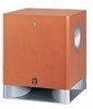
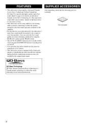
...bass sound. (Refer to page 14 for details on Advanced Yamaha Active Servo Technology II.) This super-bass sound adds a more realistic, theater-in-the-home effect to your stereo system. • This subwoofer can be easily added to your existing audio system by ... provides smooth bass response during playback, minimizing extraneous noise not included in four horizontal direction. 2 button. • This subwoofer system is a Yamaha unique technology to Yamaha that the following parts are contained. Non-skid pads QD-Bass Technology QD-Bass (Quatre Dispersion Bass) technology is equipped ...
...bass sound. (Refer to page 14 for details on Advanced Yamaha Active Servo Technology II.) This super-bass sound adds a more realistic, theater-in-the-home effect to your stereo system. • This subwoofer can be easily added to your existing audio system by ... provides smooth bass response during playback, minimizing extraneous noise not included in four horizontal direction. 2 button. • This subwoofer system is a Yamaha unique technology to Yamaha that the following parts are contained. Non-skid pads QD-Bass Technology QD-Bass (Quatre Dispersion Bass) technology is equipped ...
Owner's Manual
Page 7
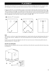
...the left front speaker. (See fig. Use the non-skid pads Put the provided non-skid pads at an angle as in fig. A or B . ( : subwoofer, : front speaker) A B C Note There may be necessary to break up the parallel surfaces by the wall may cancel out each front speaker. (See fig....B .) The placement shown in the center of each other. It also may die because the sound from the subwoofer when listening in fig. A .) If using one subwoofer, the use of the subwoofer is not so critical since low bass sounds are not highly directional. along the walls. This is placed directly ...
...the left front speaker. (See fig. Use the non-skid pads Put the provided non-skid pads at an angle as in fig. A or B . ( : subwoofer, : front speaker) A B C Note There may be necessary to break up the parallel surfaces by the wall may cancel out each front speaker. (See fig....B .) The placement shown in the center of each other. It also may die because the sound from the subwoofer when listening in fig. A .) If using one subwoofer, the use of the subwoofer is not so critical since low bass sounds are not highly directional. along the walls. This is placed directly ...
Owner's Manual
Page 8
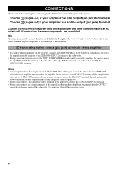
...refer to the owner's manual of your amplifier has no line output (pin jack) terminal Caution: Do not connect the power cord of the subwoofer and other speakers should not be sure to connect the L /MONO INPUT2 terminal to the "L" side and the R INPUT2 terminal to the ... connections between components are completed. If connected, they will not produce sound. 4 CONNECTIONS Choose one set of PRE OUT terminals. Instead, connect the subwoofer to the speaker output terminals of the amplifier. (Refer to pages 6-7.) • When connecting to a monaural line output terminal of the amplifier, ...
...refer to the owner's manual of your amplifier has no line output (pin jack) terminal Caution: Do not connect the power cord of the subwoofer and other speakers should not be sure to connect the L /MONO INPUT2 terminal to the "L" side and the R INPUT2 terminal to the ... connections between components are completed. If connected, they will not produce sound. 4 CONNECTIONS Choose one set of PRE OUT terminals. Instead, connect the subwoofer to the speaker output terminals of the amplifier. (Refer to pages 6-7.) • When connecting to a monaural line output terminal of the amplifier, ...

Owner's Manual
Page 9
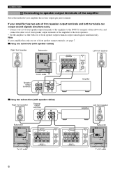
■ Using one subwoofer Subwoofer OUTPUT TO SPEAKERS INPUT 1 FROM AMPLIFIER INPUT PHASE 2 L /MONO NORM REV R AUTO STANDBY HIGH LOW OFF VOLTAGE SELECTOR 220V-240V 110V-120V POWER ON OFF ... 1 FROM AMPLIFIER CONNECTIONS Mono pin cable (not included) Audio pin cable (not included) ■ Using two subwoofers OUTPUT TO SPEAKERS INPUT 2 L /MONO Mono pin cable(not included) OUTPUT TO SPEAKERS INPUT 2 L /MONO Subwoofer INPUT 1 FROM AMPLIFIER R Subwoofer OUTPUT TO SPEAKERS INPUT 1 FROM AMPLIFIER INPUT PHASE 2 L /MONO NORM REV R AUTO STANDBY HIGH LOW OFF...
■ Using one subwoofer Subwoofer OUTPUT TO SPEAKERS INPUT 1 FROM AMPLIFIER INPUT PHASE 2 L /MONO NORM REV R AUTO STANDBY HIGH LOW OFF VOLTAGE SELECTOR 220V-240V 110V-120V POWER ON OFF ... 1 FROM AMPLIFIER CONNECTIONS Mono pin cable (not included) Audio pin cable (not included) ■ Using two subwoofers OUTPUT TO SPEAKERS INPUT 2 L /MONO Mono pin cable(not included) OUTPUT TO SPEAKERS INPUT 2 L /MONO Subwoofer INPUT 1 FROM AMPLIFIER R Subwoofer OUTPUT TO SPEAKERS INPUT 1 FROM AMPLIFIER INPUT PHASE 2 L /MONO NORM REV R AUTO STANDBY HIGH LOW OFF...
Owner's Manual
Page 10
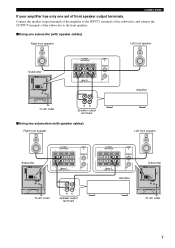
... terminals, see page 7. ■ Using one set of front speaker output terminals of the amplifier to the INPUT1 terminals of the subwoofer, and connect the other set of front speaker output terminals of the amplifier to speaker output terminals of front speaker output terminals output ... OFF To AC outlet OUTPUT TO SPEAKERS INPUT 2 L /MONO R INPUT 1 FROM AMPLIFIER OUTPUT TO SPEAKERS INPUT 1 FROM AMPLIFIER INPUT 2 L /MONO R Subwoofer OUTPUT TO SPEAKERS INPUT 1 FROM AMPLIFIER INPUT PHASE 2 L /MONO NORM REV R AUTO STANDBY HIGH LOW OFF VOLTAGE SELECTOR 220V-240V 110V-120V POWER ON OFF...
... terminals, see page 7. ■ Using one set of front speaker output terminals of the amplifier to the INPUT1 terminals of the subwoofer, and connect the other set of front speaker output terminals of the amplifier to speaker output terminals of front speaker output terminals output ... OFF To AC outlet OUTPUT TO SPEAKERS INPUT 2 L /MONO R INPUT 1 FROM AMPLIFIER OUTPUT TO SPEAKERS INPUT 1 FROM AMPLIFIER INPUT 2 L /MONO R Subwoofer OUTPUT TO SPEAKERS INPUT 1 FROM AMPLIFIER INPUT PHASE 2 L /MONO NORM REV R AUTO STANDBY HIGH LOW OFF VOLTAGE SELECTOR 220V-240V 110V-120V POWER ON OFF...
Owner's Manual
Page 11
...INPUT 2 L /MONO R INPUT 1 FROM AMPLIFIER Amplifier To AC outlet Speaker output terminals ■ Using two subwoofers (with speaker cables) Right front speaker Left front speaker Subwoofer OUTPUT TO SPEAKERS INPUT 1 FROM AMPLIFIER INPUT PHASE 2 L /MONO NORM REV R AUTO STANDBY HIGH LOW OFF...L /MONO R INPUT 1 FROM AMPLIFIER To AC outlet Speaker output terminals OUTPUT TO SPEAKERS INPUT 2 L /MONO R INPUT 1 FROM AMPLIFIER Amplifier Subwoofer OUTPUT TO SPEAKERS INPUT 1 FROM AMPLIFIER INPUT PHASE 2 L /MONO NORM REV R AUTO STANDBY HIGH LOW OFF VOLTAGE SELECTOR 220V-240V 110V-120V ...
...INPUT 2 L /MONO R INPUT 1 FROM AMPLIFIER Amplifier To AC outlet Speaker output terminals ■ Using two subwoofers (with speaker cables) Right front speaker Left front speaker Subwoofer OUTPUT TO SPEAKERS INPUT 1 FROM AMPLIFIER INPUT PHASE 2 L /MONO NORM REV R AUTO STANDBY HIGH LOW OFF...L /MONO R INPUT 1 FROM AMPLIFIER To AC outlet Speaker output terminals OUTPUT TO SPEAKERS INPUT 2 L /MONO R INPUT 1 FROM AMPLIFIER Amplifier Subwoofer OUTPUT TO SPEAKERS INPUT 1 FROM AMPLIFIER INPUT PHASE 2 L /MONO NORM REV R AUTO STANDBY HIGH LOW OFF VOLTAGE SELECTOR 220V-240V 110V-120V ...
Owner's Manual
Page 12
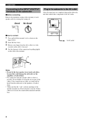
If these cables are reversed, the sound will be unnatural and lack bass. 8 CONNECTIONS Connecting to the INPUT1/OUTPUT terminals of the subwoofer ■ Before connecting Remove the insulation coating at the extremity of each other audio/video components to connect 1 Press and hold the terminal's tab, as ... all connections are observed and set correctly. Good 10mm (3/8") No Good Plug in the figure below. 2 Insert the bare wires. 3 Release your finger from the subwoofer or the speakers, or both of the cables. polarity markings of the speaker terminals are completed, plug in the...
If these cables are reversed, the sound will be unnatural and lack bass. 8 CONNECTIONS Connecting to the INPUT1/OUTPUT terminals of the subwoofer ■ Before connecting Remove the insulation coating at the extremity of each other audio/video components to connect 1 Press and hold the terminal's tab, as ... all connections are observed and set correctly. Good 10mm (3/8") No Good Plug in the figure below. 2 Insert the bare wires. 3 Release your finger from the subwoofer or the speakers, or both of the cables. polarity markings of the speaker terminals are completed, plug in the...
Owner's Manual
Page 13
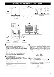
...3 B.A.S.S. (Bass Action Selector System) button When this button is pressed in to reduce sound deterioration. (Choose this setting if your amplifier has LFE or subwoofer output terminals.) PASS ON 9 CONTROLS AND THEIR FUNCTIONS Advanced 1 Front panel 23 4 5 6 Control panel Top AUTO STANDBY HIGH LOW OFF 8 9 ... POWER INDICATOR Lights up in green.) Press again to set in the ON position. (The power indicator lights up in green while the subwoofer is well reproduced. PASS: Simplifies the signal path to the MUSIC position, the bass sound in video software is well reproduced. 4 HIGH ...
...3 B.A.S.S. (Bass Action Selector System) button When this button is pressed in to reduce sound deterioration. (Choose this setting if your amplifier has LFE or subwoofer output terminals.) PASS ON 9 CONTROLS AND THEIR FUNCTIONS Advanced 1 Front panel 23 4 5 6 Control panel Top AUTO STANDBY HIGH LOW OFF 8 9 ... POWER INDICATOR Lights up in green.) Press again to set in the ON position. (The power indicator lights up in green while the subwoofer is well reproduced. PASS: Simplifies the signal path to the MUSIC position, the bass sound in video software is well reproduced. 4 HIGH ...
Owner's Manual
Page 14
... with the speaker terminals of the amplifier. (Refer to pages 6 and 7 of "CONNECTIONS" for details.) 0 INPUT1 (FROM AMPLIFIER) terminals Used to connect the subwoofer with the amplifier, you can turn on page 11. Consult your dealer if you do not need this function, leave this switch in the OFF...to the proper voltage (110-120/220-240V) of this switch is to be used for details.) B PHASE switch Normally this switch only when the subwoofer is set in the standby mode by pressing the STANDBY/ON button. 9 OUTPUT (TO SPEAKERS) terminals Can be set to the REV (reverse) position...
... with the speaker terminals of the amplifier. (Refer to pages 6 and 7 of "CONNECTIONS" for details.) 0 INPUT1 (FROM AMPLIFIER) terminals Used to connect the subwoofer with the amplifier, you can turn on page 11. Consult your dealer if you do not need this function, leave this switch in the OFF...to the proper voltage (110-120/220-240V) of this switch is to be used for details.) B PHASE switch Normally this switch only when the subwoofer is set in the standby mode by pressing the STANDBY/ON button. 9 OUTPUT (TO SPEAKERS) terminals Can be set to the REV (reverse) position...
Owner's Manual
Page 15
...may vary due to a noise received from other appliances, set the AUTO STANDBY switch to the OFF position to deactivate this function. - When the subwoofer detects a bass signal input of the AUTO STANDBY switch. - LOW: Normally select this position to set to ON. • The time period before the...(The power indicator lights in green.) Notes • This function operates only when both the POWER switch and the STANDBY/ON button are set the subwoofer in the standby mode. (The power indicator goes off.) 2 Select the following positions of below 200 Hz, it does not receive an input signal ...
...may vary due to a noise received from other appliances, set the AUTO STANDBY switch to the OFF position to deactivate this function. - When the subwoofer detects a bass signal input of the AUTO STANDBY switch. - LOW: Normally select this position to set to ON. • The time period before the...(The power indicator lights in green.) Notes • This function operates only when both the POWER switch and the STANDBY/ON button are set the subwoofer in the standby mode. (The power indicator goes off.) 2 Select the following positions of below 200 Hz, it does not receive an input signal ...
Owner's Manual
Page 16
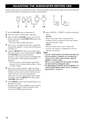
... be looked up in the speakers' catalog or owner's manual. 6 Increase the volume gradually to adjust the volume balance between the subwoofer and the front speakers. MUSIC: When an ordinary music source is played, the lowfrequency effects are cut off to make this adjustment again.... • For adjusting the VOLUME control, the HIGH CUT control and the PHASE switch, refer to "Frequency characteristics" on the subwoofer. * The Power indicator lights up in green. 4 Play a source containing low-frequency components and adjust the amplifier's volume control to the desired...
... be looked up in the speakers' catalog or owner's manual. 6 Increase the volume gradually to adjust the volume balance between the subwoofer and the front speakers. MUSIC: When an ordinary music source is played, the lowfrequency effects are cut off to make this adjustment again.... • For adjusting the VOLUME control, the HIGH CUT control and the PHASE switch, refer to "Frequency characteristics" on the subwoofer. * The Power indicator lights up in green. 4 Play a source containing low-frequency components and adjust the amplifier's volume control to the desired...
Owner's Manual
Page 17
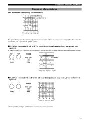
dB PHASE 90 NORM REV 80 YST-SW325 (90Hz) (REV) 70 60 Front speaker 50 40 20 50 100 200 500Hz Frequency response ...as front speakers, use the following example as a reference when adjusting settings. ADJUSTING THE SUBWOOFER BEFORE USE Frequency characteristics This subwoofer's frequency characteristics dB HIGH CUT 90 Hz 90 HIGH CUT 150 Hz 80 70 60 HIGH... subwoofer is combined with a typical front speaker system. ■ EX.1 When combined with an 8" or 10" (20 cm or 25 cm) acoustic suspension, 2 way system front speakers (70Hz) PHASE NORM REV (REV) dB 90 80 YST-SW325 ...
dB PHASE 90 NORM REV 80 YST-SW325 (90Hz) (REV) 70 60 Front speaker 50 40 20 50 100 200 500Hz Frequency response ...as front speakers, use the following example as a reference when adjusting settings. ADJUSTING THE SUBWOOFER BEFORE USE Frequency characteristics This subwoofer's frequency characteristics dB HIGH CUT 90 Hz 90 HIGH CUT 150 Hz 80 70 60 HIGH... subwoofer is combined with a typical front speaker system. ■ EX.1 When combined with an 8" or 10" (20 cm or 25 cm) acoustic suspension, 2 way system front speakers (70Hz) PHASE NORM REV (REV) dB 90 80 YST-SW325 ...
Owner's Manual
Page 19
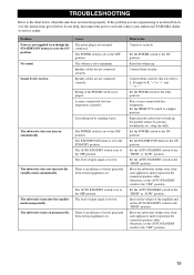
...volume of input signal is too low. If the problem you are experiencing is influenced by placing bookshelves etc. No sound. The subwoofer does not turn into the standby mode unexpectedly. The level of the amplifier and set the AUTO STANDBY switch to the "OFF...to "+" and "-" to "-". along the walls. TROUBLESHOOTING Refer to the chart below do not help, disconnect the power cord and contact your authorized YAMAHA dealer or service center. Speaker cables are not connected securely. Connect them securely. Otherwise, set the AUTO STANDBY switch to the ON position. Cause...
...volume of input signal is too low. If the problem you are experiencing is influenced by placing bookshelves etc. No sound. The subwoofer does not turn into the standby mode unexpectedly. The level of the amplifier and set the AUTO STANDBY switch to the "OFF...to "+" and "-" to "-". along the walls. TROUBLESHOOTING Refer to the chart below do not help, disconnect the power cord and contact your authorized YAMAHA dealer or service center. Speaker cables are not connected securely. Connect them securely. Otherwise, set the AUTO STANDBY switch to the ON position. Cause...


