Owner's Manual
Page 2
...any ventilation openings. Model: Serial No.: The serial number is required when the apparatus has been damaged in any heat sources such as power-supply cord or plug is damaged, liquid has been spilled or objects have fallen into your safety. Install in accordance with one wider than... being walked on the rear of the main unit. Retain this Owner's Manual in a safe place for replacement of the obsolete outlet. 10 Protect the power cord from the apparatus. 11 Only use caution when moving the cart/ apparatus combination to the presence of important operating and maintenance (servicing)...
...any ventilation openings. Model: Serial No.: The serial number is required when the apparatus has been damaged in any heat sources such as power-supply cord or plug is damaged, liquid has been spilled or objects have fallen into your safety. Install in accordance with one wider than... being walked on the rear of the main unit. Retain this Owner's Manual in a safe place for replacement of the obsolete outlet. 10 Protect the power cord from the apparatus. 11 Only use caution when moving the cart/ apparatus combination to the presence of important operating and maintenance (servicing)...
Owner's Manual
Page 11
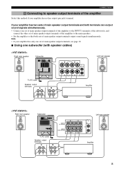
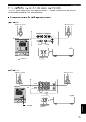
... simultaneously. • Connect one set of main speaker output terminals of the amplifier to the INPUT1 terminals of the subwoofer, and connect the other set of main speaker output terminals, see page 10. ■ Using one set of main speaker output terminals of the amplifier to speaker output terminals of main speaker...
... simultaneously. • Connect one set of main speaker output terminals of the amplifier to the INPUT1 terminals of the subwoofer, and connect the other set of main speaker output terminals, see page 10. ■ Using one set of main speaker output terminals of the amplifier to speaker output terminals of main speaker...
Owner's Manual
Page 13
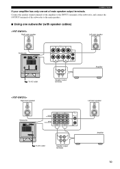
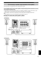
CONNECTIONS If your amplifier has only one subwoofer (with speaker cables) Right main speaker Left main speaker Subwoofer To AC outlet Right main speaker Speaker output terminals Amplifier Left main speaker Subwoofer To AC outlet Speaker output terminals Amplifier 10 Connect the speaker output terminals of the amplifier to the main speakers. ■ Using one set of the subwoofer to the INPUT1 terminals of the subwoofer, and connect the OUTPUT terminals of main speaker output terminals.
CONNECTIONS If your amplifier has only one subwoofer (with speaker cables) Right main speaker Left main speaker Subwoofer To AC outlet Right main speaker Speaker output terminals Amplifier Left main speaker Subwoofer To AC outlet Speaker output terminals Amplifier 10 Connect the speaker output terminals of the amplifier to the main speakers. ■ Using one set of the subwoofer to the INPUT1 terminals of the subwoofer, and connect the OUTPUT terminals of main speaker output terminals.
Owner's Manual
Page 17
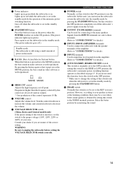
... and counterclockwise to decrease the volume. 6 VOLTAGE SELECTOR switch (China, Korea and General models only) If the preset setting of this control represents 10 Hz. 5 VOLUME control Adjusts the volume level. If you do not need this function, leave this switch in the OFF position. * Make ...your dealer if you can turn on the subwoofer or turn on the power when the POWER switch is set in the ON position. (The power indicator lights up in green.) Press again to set the subwoofer in the standby mode. (The power indicator goes off the subwoofer's power supply from the amplifier. (Refer to ...
... and counterclockwise to decrease the volume. 6 VOLTAGE SELECTOR switch (China, Korea and General models only) If the preset setting of this control represents 10 Hz. 5 VOLUME control Adjusts the volume level. If you do not need this function, leave this switch in the OFF position. * Make ...your dealer if you can turn on the subwoofer or turn on the power when the POWER switch is set in the ON position. (The power indicator lights up in green.) Press again to set the subwoofer in the standby mode. (The power indicator goes off the subwoofer's power supply from the amplifier. (Refer to ...
Owner's Manual
Page 20
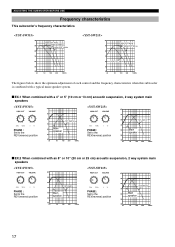
... 100 200 500Hz The figures below show the optimum adjustment of each control and the frequency characteristics when this subwoofer is combined with a typical main speaker system. ■ EX.1 When combined with a 4" or 5" (10 cm or 13 cm) acoustic suspension, 2 way system main speakers PHASE : Set to the REV(reverse) ...40 20 50 100 200 500Hz PHASE : Set to the REV(reverse) position dB 90 80 YST-SW215 70 60 Main speaker 50 40 20 50 100 200 500Hz ■ EX.2 When combined with an 8" or 10" (20 cm or 25 cm) acoustic suspension, 2 way system main speakers PHASE : Set to...
... 100 200 500Hz The figures below show the optimum adjustment of each control and the frequency characteristics when this subwoofer is combined with a typical main speaker system. ■ EX.1 When combined with a 4" or 5" (10 cm or 13 cm) acoustic suspension, 2 way system main speakers PHASE : Set to the REV(reverse) ...40 20 50 100 200 500Hz PHASE : Set to the REV(reverse) position dB 90 80 YST-SW215 70 60 Main speaker 50 40 20 50 100 200 500Hz ■ EX.2 When combined with an 8" or 10" (20 cm or 25 cm) acoustic suspension, 2 way system main speakers PHASE : Set to...
Owner's Manual
Page 23
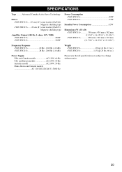
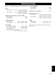
SPECIFICATIONS Type ........ Advanced Yamaha Active Servo Technology Driver .....25 cm (10") cone woofer (JA2564) Magnetic shielding type .......20 cm (8") cone woofer (JA2165) Magnetic shielding type Amplifier Output (100 Hz, 5 ohms, 10% THD)
SPECIFICATIONS Type ........ Advanced Yamaha Active Servo Technology Driver .....25 cm (10") cone woofer (JA2564) Magnetic shielding type .......20 cm (8") cone woofer (JA2165) Magnetic shielding type Amplifier Output (100 Hz, 5 ohms, 10% THD)
User Manual
Page 9
...sets of the amplifier Select this method if your amplifier has only one subwoofer (with speaker cables) Right main speaker Subwoofer Left main speaker To AC outlet Speaker output terminals Amplifier Right main speaker Subwoofer To AC outlet Speaker output terminals Left main speaker Amplifier 8 English ...Connect one set of main speaker output terminals of the amplifier to the INPUT1 terminals of the subwoofer, and connect the other set of main speaker output terminals, see page 10. ■ Using one set of main speaker output terminals of the amplifier to speaker output ...
...sets of the amplifier Select this method if your amplifier has only one subwoofer (with speaker cables) Right main speaker Subwoofer Left main speaker To AC outlet Speaker output terminals Amplifier Right main speaker Subwoofer To AC outlet Speaker output terminals Left main speaker Amplifier 8 English ...Connect one set of main speaker output terminals of the amplifier to the INPUT1 terminals of the subwoofer, and connect the other set of main speaker output terminals, see page 10. ■ Using one set of main speaker output terminals of the amplifier to speaker output ...
User Manual
Page 11
CONNECTIONS If your amplifier has only one subwoofer (with speaker cables) Right main speaker Left main speaker Subwoofer To AC outlet Right main speaker Speaker output terminals Amplifier Left main speaker Subwoofer To AC outlet Speaker output terminals Amplifier 10 English Connect the speaker output terminals of the amplifier to the main speakers. ■ Using one set of the subwoofer to the INPUT1 terminals of the subwoofer, and connect the OUTPUT terminals of main speaker output terminals.
CONNECTIONS If your amplifier has only one subwoofer (with speaker cables) Right main speaker Left main speaker Subwoofer To AC outlet Right main speaker Speaker output terminals Amplifier Left main speaker Subwoofer To AC outlet Speaker output terminals Amplifier 10 English Connect the speaker output terminals of the amplifier to the main speakers. ■ Using one set of the subwoofer to the INPUT1 terminals of the subwoofer, and connect the OUTPUT terminals of main speaker output terminals.

User Manual
Page 15
... setting this switch to the OFF position to the HIGH or LOW position, the subwoofer's automatic power-switching function operates as described on . 1 Power indicator Lights up in red while the subwoofer is set in the standby mode by the operation of the automatic powerswitching function. If... switch Normally this control represents 10 Hz. 5 VOLUME control Adjusts the volume level. CONTROLS AND THEIR FUNCTIONS 7 POWER switch Normally, set in the standby mode. 2 STANDBY/ON button Press this button to turn on the subwoofer or turn on the power when the POWER switch is set in the ...
... setting this switch to the OFF position to the HIGH or LOW position, the subwoofer's automatic power-switching function operates as described on . 1 Power indicator Lights up in red while the subwoofer is set in the standby mode by the operation of the automatic powerswitching function. If... switch Normally this control represents 10 Hz. 5 VOLUME control Adjusts the volume level. CONTROLS AND THEIR FUNCTIONS 7 POWER switch Normally, set in the standby mode. 2 STANDBY/ON button Press this button to turn on the subwoofer or turn on the power when the POWER switch is set in the ...

User Manual
Page 18
... 100 200 500Hz The figures below show the optimum adjustment of each control and the frequency characteristics when this subwoofer is combined with a typical main speaker system. ■ EX.1 When combined with a 4" or 5" (10 cm or 13 cm) acoustic suspension, 2 way system main speakers PHASE : Set to the REV(reverse) ...40 20 50 100 200 500Hz PHASE : Set to the REV(reverse) position dB 90 80 YST-SW215 70 60 Main speaker 50 40 20 50 100 200 500Hz ■ EX.2 When combined with an 8" or 10" (20 cm or 25 cm) acoustic suspension, 2 way system main speakers PHASE : Set to...
... 100 200 500Hz The figures below show the optimum adjustment of each control and the frequency characteristics when this subwoofer is combined with a typical main speaker system. ■ EX.1 When combined with a 4" or 5" (10 cm or 13 cm) acoustic suspension, 2 way system main speakers PHASE : Set to the REV(reverse) ...40 20 50 100 200 500Hz PHASE : Set to the REV(reverse) position dB 90 80 YST-SW215 70 60 Main speaker 50 40 20 50 100 200 500Hz ■ EX.2 When combined with an 8" or 10" (20 cm or 25 cm) acoustic suspension, 2 way system main speakers PHASE : Set to...
User Manual
Page 21
SPECIFICATIONS Type ........ Advanced Yamaha Active Servo Technology Driver .....25 cm (10") cone woofer (JA2564) Magnetic shielding type .......20 cm (8") cone woofer (JA2165) Magnetic shielding type Amplifier Output (100 Hz, 5 ohms, 10% THD)
SPECIFICATIONS Type ........ Advanced Yamaha Active Servo Technology Driver .....25 cm (10") cone woofer (JA2564) Magnetic shielding type .......20 cm (8") cone woofer (JA2165) Magnetic shielding type Amplifier Output (100 Hz, 5 ohms, 10% THD)