Owner's Manual
Page 4
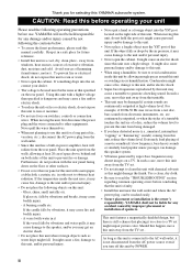
...a foreign object into the set might cause a fire, damage to use this unit for selecting this YAMAHA subwoofer system. Furthermore, do not position with a higher voltage than specified is dangerous and may cause bodily injury...foreign objects such as it too close to this manual carefully. iii If something drops into the YST port located on the right side of excessive vibration, dust, moisture and cold. If glass etc.... a chance that specified on switches, controls or connection wires. For example, if 20 Hz-50 Hz sine waves from a test disc, bass sounds from the TV set . • ...
...a foreign object into the set might cause a fire, damage to use this unit for selecting this YAMAHA subwoofer system. Furthermore, do not position with a higher voltage than specified is dangerous and may cause bodily injury...foreign objects such as it too close to this manual carefully. iii If something drops into the YST port located on the right side of excessive vibration, dust, moisture and cold. If glass etc.... a chance that specified on switches, controls or connection wires. For example, if 20 Hz-50 Hz sine waves from a test disc, bass sounds from the TV set . • ...
Owner's Manual
Page 5
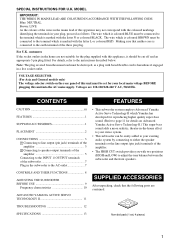
...-bass sound adds a more realistic, theater-in a live socket outlet. CONTROLS AND THEIR FUNCTIONS 8 ADJUSTING THE SUBWOOFER BEFORE USE 9 Frequency characteristics 10 ADVANCED YAMAHA ACTIVE SERVO TECHNOLOGY II 11 SUPPLIED ACCESSORIES After unpacking, check that neither core is marked with two positions (HIGH... flexible cord is marked with the coloured markings identifying the terminals in the subwoofer to the instructions described below. SPECIAL INSTRUCTIONS FOR U.K. Voltages are 110-120/220-240 V AC, 50/60 Hz. MODEL IMPORTANT: THE WIRES IN MAINS LEAD ARE COLOURED IN ACCORDANCE...
...-bass sound adds a more realistic, theater-in a live socket outlet. CONTROLS AND THEIR FUNCTIONS 8 ADJUSTING THE SUBWOOFER BEFORE USE 9 Frequency characteristics 10 ADVANCED YAMAHA ACTIVE SERVO TECHNOLOGY II 11 SUPPLIED ACCESSORIES After unpacking, check that neither core is marked with two positions (HIGH... flexible cord is marked with the coloured markings identifying the terminals in the subwoofer to the instructions described below. SPECIAL INSTRUCTIONS FOR U.K. Voltages are 110-120/220-240 V AC, 50/60 Hz. MODEL IMPORTANT: THE WIRES IN MAINS LEAD ARE COLOURED IN ACCORDANCE...
Owner's Manual
Page 6
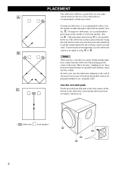
...shown in fig. This is recommended to break up the parallel surfaces by vibrations etc. ( : subwoofer, : front speaker) 2 It also may cancel out each front speaker. (See fig. If using two subwoofers, it on your audio A system, however, the use of either the right or the left ...front speaker. (See fig. A or B . A .) If using one subwoofer, it is recommended to prevent the subwoofer from the subwoofer when listening in fig. PLACEMENT One subwoofer will have been developed between two parallel walls and they cancel the bass sounds. C is also possible,...
...shown in fig. This is recommended to break up the parallel surfaces by vibrations etc. ( : subwoofer, : front speaker) 2 It also may cancel out each front speaker. (See fig. If using two subwoofers, it on your audio A system, however, the use of either the right or the left ...front speaker. (See fig. A or B . A .) If using one subwoofer, it is recommended to prevent the subwoofer from the subwoofer when listening in fig. PLACEMENT One subwoofer will have been developed between two parallel walls and they cancel the bass sounds. C is also possible,...
Owner's Manual
Page 7
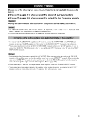
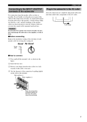
... be connected to the subwoofer. • After all connections are completed, plug in the subwoofer and other audio/video components. 1 Connecting to line output (pin jack) terminals of the amplifier • To connect with a YAMAHA DSP amplifier (or AV receiver), connect the SUBWOOFER (or LOW PASS etc....) terminal on the rear of the DSP amplifier (or AV receiver) to the L /MONO INPUT 2 terminal of the subwoofer. • When connecting the subwoofer to the SPLIT SUBWOOFER terminals on the rear panel...
... be connected to the subwoofer. • After all connections are completed, plug in the subwoofer and other audio/video components. 1 Connecting to line output (pin jack) terminals of the amplifier • To connect with a YAMAHA DSP amplifier (or AV receiver), connect the SUBWOOFER (or LOW PASS etc....) terminal on the rear of the DSP amplifier (or AV receiver) to the L /MONO INPUT 2 terminal of the subwoofer. • When connecting the subwoofer to the SPLIT SUBWOOFER terminals on the rear panel...
Owner's Manual
Page 8
... TO SPEAKERS INPUT 1 FROM AMPLIFIER INPUT 2 HIGH CUT /MONO HIGH LOW Amplifier Mono pin cable (not included) Audio pin cable (not included) ■ Using two subwoofers OUTPUT TO SPEAKERS INPUT 1 FROM AMPLIFIER INPUT 2 HIGH CUT /MONO HIGH LOW Mono pin cable (not included) OUTPUT TO SPEAKERS INPUT 1 FROM AMPLIFIER INPUT 2 HIGH... 2 HIGH CUT /MONO VOLUME HIGH LOW POWER ON OFF OUTPUT TO SPEAKERS INPUT 1 FROM AMPLIFIER INPUT 2 HIGH CUT /MONO VOLUME HIGH LOW POWER ON OFF Subwoofer To AC outlet Subwoofer To AC outlet Mono pin cable (not included) Amplifier 4
... TO SPEAKERS INPUT 1 FROM AMPLIFIER INPUT 2 HIGH CUT /MONO HIGH LOW Amplifier Mono pin cable (not included) Audio pin cable (not included) ■ Using two subwoofers OUTPUT TO SPEAKERS INPUT 1 FROM AMPLIFIER INPUT 2 HIGH CUT /MONO HIGH LOW Mono pin cable (not included) OUTPUT TO SPEAKERS INPUT 1 FROM AMPLIFIER INPUT 2 HIGH... 2 HIGH CUT /MONO VOLUME HIGH LOW POWER ON OFF OUTPUT TO SPEAKERS INPUT 1 FROM AMPLIFIER INPUT 2 HIGH CUT /MONO VOLUME HIGH LOW POWER ON OFF Subwoofer To AC outlet Subwoofer To AC outlet Mono pin cable (not included) Amplifier 4
Owner's Manual
Page 9
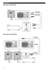
... INPUT 1 FROM AMPLIFIER INPUT 2 HIGH CUT /MONO HIGH LOW OUTPUT TO SPEAKERS INPUT 1 FROM AMPLIFIER INPUT 2 HIGH CUT /MONO HIGH LOW Subwoofer OUTPUT TO SPEAKERS INPUT 1 FROM AMPLIFIER INPUT 2 HIGH CUT /MONO VOLUME HIGH LOW POWER ON OFF To AC outlet 5 CONNECTIONS 2 Connecting to...output sound signals simultaneously. • Connect one set of front speaker output terminals of the amplifier to the INPUT 1 terminals of the subwoofer, and connect the other set of front speaker output terminals output sound signals simultaneously. Note • If your amplifier has no line...
... INPUT 1 FROM AMPLIFIER INPUT 2 HIGH CUT /MONO HIGH LOW OUTPUT TO SPEAKERS INPUT 1 FROM AMPLIFIER INPUT 2 HIGH CUT /MONO HIGH LOW Subwoofer OUTPUT TO SPEAKERS INPUT 1 FROM AMPLIFIER INPUT 2 HIGH CUT /MONO VOLUME HIGH LOW POWER ON OFF To AC outlet 5 CONNECTIONS 2 Connecting to...output sound signals simultaneously. • Connect one set of front speaker output terminals of the amplifier to the INPUT 1 terminals of the subwoofer, and connect the other set of front speaker output terminals output sound signals simultaneously. Note • If your amplifier has no line...
Owner's Manual
Page 10
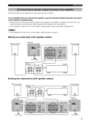
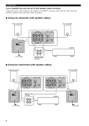
.... ■ Using one set of front speaker output terminals. CONNECTIONS If your amplifier has only one subwoofer (with speaker cables) Right front speaker Left front speaker Subwoofer OUTPUT TO SPEAKERS INPUT 1 FROM AMPLIFIER INPUT 2 HIGH CUT /MONO VOLUME HIGH LOW POWER ON OFF...AMPLIFIER INPUT 2 HIGH CUT /MONO HIGH LOW Amplifier To AC outlet Speaker output terminals ■ Using two subwoofers (with speaker cables) Right front speaker Left front speaker Subwoofer OUTPUT TO SPEAKERS INPUT 1 FROM AMPLIFIER INPUT 2 HIGH CUT /MONO VOLUME HIGH LOW POWER ON OFF OUTPUT...
.... ■ Using one set of front speaker output terminals. CONNECTIONS If your amplifier has only one subwoofer (with speaker cables) Right front speaker Left front speaker Subwoofer OUTPUT TO SPEAKERS INPUT 1 FROM AMPLIFIER INPUT 2 HIGH CUT /MONO VOLUME HIGH LOW POWER ON OFF...AMPLIFIER INPUT 2 HIGH CUT /MONO HIGH LOW Amplifier To AC outlet Speaker output terminals ■ Using two subwoofers (with speaker cables) Right front speaker Left front speaker Subwoofer OUTPUT TO SPEAKERS INPUT 1 FROM AMPLIFIER INPUT 2 HIGH CUT /MONO VOLUME HIGH LOW POWER ON OFF OUTPUT...
Owner's Manual
Page 11
...How to connect: 1 Press and hold the terminal's tab, as possible. polarity markings of the speaker cables are completed, plug in the subwoofer to the AC outlet After all connections are observed and set correctly. Make sure that the + and - If the connections are reversed, the... sound will be produced. 7 Good No Good 10 mm (3/8") Plug in the subwoofer and other , because this could damage the subwoofer or the amplifier, or both of them . ■Before connecting Remove the insulation coating at the terminal. Red: positive (+) ...
...How to connect: 1 Press and hold the terminal's tab, as possible. polarity markings of the speaker cables are completed, plug in the subwoofer to the AC outlet After all connections are observed and set correctly. Make sure that the + and - If the connections are reversed, the... sound will be produced. 7 Good No Good 10 mm (3/8") Plug in the subwoofer and other , because this could damage the subwoofer or the amplifier, or both of them . ■Before connecting Remove the insulation coating at the terminal. Red: positive (+) ...
Owner's Manual
Page 12
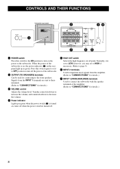
... counterclockwise to decrease the volume. 4 Power indicator Light up in green when the power switch (1) is turned on; When the power of the subwoofer is on, the power indicator (4) on the power to turn off point. Signals from the amplifier. (Refer to "CONNECTIONS" for details.) 7... HIGH CUT switch Selects the high frequency cut off the power of the amplifier. (Refer to "CONNECTIONS" for details.) 8 CONTROLS AND THEIR FUNCTIONS Subwoofer rear panel 1 OUTPUT TO SPEAKERS INPUT 1 FROM AMPLIFIER INPUT 2 HIGH CUT /MONO VOLUME HIGH LOW POWER ON OFF 2 OUTPUT TO SPEAKERS INPUT ...
... counterclockwise to decrease the volume. 4 Power indicator Light up in green when the power switch (1) is turned on; When the power of the subwoofer is on, the power indicator (4) on the power to turn off point. Signals from the amplifier. (Refer to "CONNECTIONS" for details.) 7... HIGH CUT switch Selects the high frequency cut off the power of the amplifier. (Refer to "CONNECTIONS" for details.) 8 CONTROLS AND THEIR FUNCTIONS Subwoofer rear panel 1 OUTPUT TO SPEAKERS INPUT 1 FROM AMPLIFIER INPUT 2 HIGH CUT /MONO VOLUME HIGH LOW POWER ON OFF 2 OUTPUT TO SPEAKERS INPUT ...
Owner's Manual
Page 13
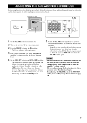
...the LOW position. If necessary, switch it to the HIGH position. 6 Rotate the VOLUME control gradually to adjust the volume balance between the subwoofer and the other components. 3 Press the POWER switch to the ON position. * The Power indicator lights up in green. 4 Play a...to the LOW or HIGH position. ADJUSTING THE SUBWOOFER BEFORE USE Before using the subwoofer, adjust the subwoofer to obtain the optimum volume and tone balance between the subwoofer and the front speakers by following the procedures described below. 3 Subwoofer rear panel OUTPUT TO SPEAKERS INPUT 1 FROM AMPLIFIER...
...the LOW position. If necessary, switch it to the HIGH position. 6 Rotate the VOLUME control gradually to adjust the volume balance between the subwoofer and the other components. 3 Press the POWER switch to the ON position. * The Power indicator lights up in green. 4 Play a...to the LOW or HIGH position. ADJUSTING THE SUBWOOFER BEFORE USE Before using the subwoofer, adjust the subwoofer to obtain the optimum volume and tone balance between the subwoofer and the front speakers by following the procedures described below. 3 Subwoofer rear panel OUTPUT TO SPEAKERS INPUT 1 FROM AMPLIFIER...

Owner's Manual
Page 14
... Frequency response The frequency response of this subwoofer dB 90 HIGH CUT HIGH 80 70 60 HIGH CUT LOW 50 40 20 50 100 200 500Hz The figures below show the optimum adjustment of each control and the frequency characteristics when this subwoofer is combined with a typical front speaker ...system. ■EX.1 When combined with a 4" or 6.5" (10 cm or 16 cm) acoustic suspension, 2 way system front speakers HIGH CUT VOLUME HIGH LOW dB 90 80 YST-SW216 70 60 Front speaker 50 40 20 50 100 200 500Hz ...
... Frequency response The frequency response of this subwoofer dB 90 HIGH CUT HIGH 80 70 60 HIGH CUT LOW 50 40 20 50 100 200 500Hz The figures below show the optimum adjustment of each control and the frequency characteristics when this subwoofer is combined with a typical front speaker ...system. ■EX.1 When combined with a 4" or 6.5" (10 cm or 16 cm) acoustic suspension, 2 way system front speakers HIGH CUT VOLUME HIGH LOW dB 90 80 YST-SW216 70 60 Front speaker 50 40 20 50 100 200 500Hz ...
Owner's Manual
Page 16
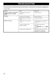
... by standing waves. Connect them correctly, that is set to the ON position. Reposition the subwoofer or break up . TROUBLESHOOTING Refer to the chart below do not help, disconnect the power cord and contact your authorized YAMAHA dealer or service center. Problem Power is not supplied even though the POWER switch is...
... by standing waves. Connect them correctly, that is set to the ON position. Reposition the subwoofer or break up . TROUBLESHOOTING Refer to the chart below do not help, disconnect the power cord and contact your authorized YAMAHA dealer or service center. Problem Power is not supplied even though the POWER switch is...


