Owner's Manual
Page 2
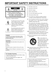
... the presence of important operating and maintenance (servicing) instructions in the literature accompanying the appliance. Model: Serial No.: The serial number is located on the unit: A vessel with water in a safe place for long periods of time. 14 Refer all instructions. 5 Do not use attachments/accessories specified by the manufacturer. 12Use only with the cart, stand, tripod, bracket, or table specified...
... the presence of important operating and maintenance (servicing) instructions in the literature accompanying the appliance. Model: Serial No.: The serial number is located on the unit: A vessel with water in a safe place for long periods of time. 14 Refer all instructions. 5 Do not use attachments/accessories specified by the manufacturer. 12Use only with the cart, stand, tripod, bracket, or table specified...
Owner's Manual
Page 3
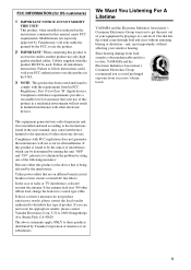
... excessive volume levels. Utilize power outlets that interference will not result in to the operation of America or its subsidiaries. ii This product, when installed as indicated in the instructions contained in the users manual, may void your authority, granted by Yamaha Corporation of other electronic devices. Modifications not expressly approved by Yamaha may cause interference harmful to coaxial type cable. Failure...
... excessive volume levels. Utilize power outlets that interference will not result in to the operation of America or its subsidiaries. ii This product, when installed as indicated in the instructions contained in the users manual, may void your authority, granted by Yamaha Corporation of other electronic devices. Modifications not expressly approved by Yamaha may cause interference harmful to coaxial type cable. Failure...
Owner's Manual
Page 4
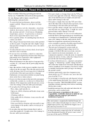
... of a movie soundtrack's low frequency, bass-heavy sounds or similarly loud popular music passages can be reached easily. • Secure placement or installation is not disconnected from the AC power source even if you may cause damage to rain or moisture. • Do not use this unit for selecting this YAMAHA subwoofer system. are continuously outputted at least 20 cm of...
... of a movie soundtrack's low frequency, bass-heavy sounds or similarly loud popular music passages can be reached easily. • Secure placement or installation is not disconnected from the AC power source even if you may cause damage to rain or moisture. • Do not use this unit for selecting this YAMAHA subwoofer system. are continuously outputted at least 20 cm of...
Owner's Manual
Page 5
... the instructions described below. Note: The plug severed from the mains lead must be destroyed, as follows: The wire which is connected to the earth terminal of the amplifier. • The HIGH CUT switch provides you with the letter L or coloured RED. Voltages are contained. CONTROLS AND THEIR FUNCTIONS 8 ADJUSTING THE SUBWOOFER BEFORE USE 9 Frequency characteristics 10 ADVANCED YAMAHA ACTIVE SERVO TECHNOLOGY II 11 SUPPLIED...
... the instructions described below. Note: The plug severed from the mains lead must be destroyed, as follows: The wire which is connected to the earth terminal of the amplifier. • The HIGH CUT switch provides you with the letter L or coloured RED. Voltages are contained. CONTROLS AND THEIR FUNCTIONS 8 ADJUSTING THE SUBWOOFER BEFORE USE 9 Frequency characteristics 10 ADVANCED YAMAHA ACTIVE SERVO TECHNOLOGY II 11 SUPPLIED...
Owner's Manual
Page 6
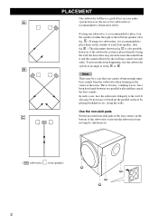
... using one subwoofer, it is placed directly facing the wall, the bass effect may lessen because the sound from it and the sound reflected by the wall may be a case that you cannot obtain enough superbass sounds from the subwoofer when listening in the center of each other. A or B . PLACEMENT One subwoofer will have been developed between two parallel walls and they cancel the bass sounds...
... using one subwoofer, it is placed directly facing the wall, the bass effect may lessen because the sound from it and the sound reflected by the wall may be a case that you cannot obtain enough superbass sounds from the subwoofer when listening in the center of each other. A or B . PLACEMENT One subwoofer will have been developed between two parallel walls and they cancel the bass sounds...
Owner's Manual
Page 7
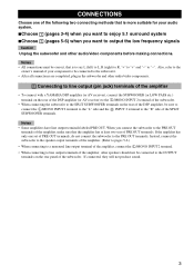
... rear panel of the SPLIT SUBWOOFER terminals. When you want to output the low frequency signals Caution Unplug the subwoofer and other audio/video components. 1 Connecting to line output (pin jack) terminals of the amplifier • To connect with a YAMAHA DSP amplifier (or AV receiver), connect the SUBWOOFER (or LOW PASS etc.) terminal on the rear of the DSP amplifier (or AV receiver) to the L /MONO INPUT 2 terminal of the subwoofer. • When connecting...
... rear panel of the SPLIT SUBWOOFER terminals. When you want to output the low frequency signals Caution Unplug the subwoofer and other audio/video components. 1 Connecting to line output (pin jack) terminals of the amplifier • To connect with a YAMAHA DSP amplifier (or AV receiver), connect the SUBWOOFER (or LOW PASS etc.) terminal on the rear of the DSP amplifier (or AV receiver) to the L /MONO INPUT 2 terminal of the subwoofer. • When connecting...
Owner's Manual
Page 8
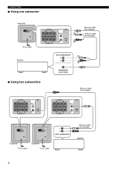
CONNECTIONS ■ Using one subwoofer Subwoofer OUTPUT TO SPEAKERS INPUT 1 FROM AMPLIFIER INPUT 2 HIGH CUT /MONO VOLUME HIGH LOW POWER ON OFF To AC outlet OUTPUT TO SPEAKERS INPUT 1 FROM AMPLIFIER INPUT 2 HIGH CUT /MONO HIGH LOW Amplifier Mono pin cable (not included) Audio pin cable (not included) ■ Using two subwoofers OUTPUT TO SPEAKERS INPUT 1 FROM AMPLIFIER INPUT 2 HIGH CUT /MONO HIGH LOW Mono pin cable (not included) OUTPUT TO SPEAKERS INPUT 1 FROM AMPLIFIER INPUT 2 HIGH CUT /MONO HIGH LOW OUTPUT TO SPEAKERS INPUT 1 FROM AMPLIFIER INPUT 2 HIGH...
CONNECTIONS ■ Using one subwoofer Subwoofer OUTPUT TO SPEAKERS INPUT 1 FROM AMPLIFIER INPUT 2 HIGH CUT /MONO VOLUME HIGH LOW POWER ON OFF To AC outlet OUTPUT TO SPEAKERS INPUT 1 FROM AMPLIFIER INPUT 2 HIGH CUT /MONO HIGH LOW Amplifier Mono pin cable (not included) Audio pin cable (not included) ■ Using two subwoofers OUTPUT TO SPEAKERS INPUT 1 FROM AMPLIFIER INPUT 2 HIGH CUT /MONO HIGH LOW Mono pin cable (not included) OUTPUT TO SPEAKERS INPUT 1 FROM AMPLIFIER INPUT 2 HIGH CUT /MONO HIGH LOW OUTPUT TO SPEAKERS INPUT 1 FROM AMPLIFIER INPUT 2 HIGH...
Owner's Manual
Page 9
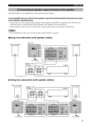
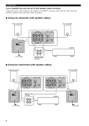
... can output sound signals simultaneously. • Connect one subwoofer (with speaker cables) Right front speaker Subwoofer OUTPUT TO SPEAKERS INPUT 1 FROM AMPLIFIER INPUT 2 HIGH CUT /MONO VOLUME HIGH LOW POWER ON OFF To AC outlet Speaker output terminals OUTPUT TO SPEAKERS INPUT 1 FROM AMPLIFIER INPUT 2 HIGH CUT /MONO HIGH LOW Left front speaker Amplifier ■ Using two subwoofers (with speaker cables) Right front speaker Speaker output terminals Amplifier Left front speaker Subwoofer OUTPUT TO SPEAKERS INPUT 1 FROM AMPLIFIER INPUT 2 HIGH CUT /MONO VOLUME HIGH...
... can output sound signals simultaneously. • Connect one subwoofer (with speaker cables) Right front speaker Subwoofer OUTPUT TO SPEAKERS INPUT 1 FROM AMPLIFIER INPUT 2 HIGH CUT /MONO VOLUME HIGH LOW POWER ON OFF To AC outlet Speaker output terminals OUTPUT TO SPEAKERS INPUT 1 FROM AMPLIFIER INPUT 2 HIGH CUT /MONO HIGH LOW Left front speaker Amplifier ■ Using two subwoofers (with speaker cables) Right front speaker Speaker output terminals Amplifier Left front speaker Subwoofer OUTPUT TO SPEAKERS INPUT 1 FROM AMPLIFIER INPUT 2 HIGH CUT /MONO VOLUME HIGH...
Owner's Manual
Page 10
...to the front speakers. ■ Using one set of front speaker output terminals. CONNECTIONS If your amplifier has only one subwoofer (with speaker cables) Right front speaker Left front speaker Subwoofer OUTPUT TO SPEAKERS INPUT 1 FROM AMPLIFIER INPUT 2 HIGH CUT /MONO VOLUME HIGH LOW POWER ON OFF OUTPUT TO SPEAKERS INPUT 1 FROM AMPLIFIER INPUT 2 HIGH CUT /MONO HIGH LOW Amplifier To AC outlet Speaker output terminals ■ Using two subwoofers (with speaker cables) Right front speaker Left front speaker Subwoofer OUTPUT TO SPEAKERS INPUT 1 FROM AMPLIFIER INPUT 2 HIGH...
...to the front speakers. ■ Using one set of front speaker output terminals. CONNECTIONS If your amplifier has only one subwoofer (with speaker cables) Right front speaker Left front speaker Subwoofer OUTPUT TO SPEAKERS INPUT 1 FROM AMPLIFIER INPUT 2 HIGH CUT /MONO VOLUME HIGH LOW POWER ON OFF OUTPUT TO SPEAKERS INPUT 1 FROM AMPLIFIER INPUT 2 HIGH CUT /MONO HIGH LOW Amplifier To AC outlet Speaker output terminals ■ Using two subwoofers (with speaker cables) Right front speaker Left front speaker Subwoofer OUTPUT TO SPEAKERS INPUT 1 FROM AMPLIFIER INPUT 2 HIGH...
Owner's Manual
Page 11
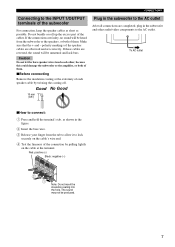
... amplifier, or both of them . ■Before connecting Remove the insulation coating at the extremity of each speaker cable by pulling lightly on the cable at the terminal. Good No Good 10 mm (3/8") Plug in the subwoofer to the AC outlet After all connections are observed and set correctly. Make sure that the + and - CONNECTIONS Connecting to the INPUT 1/OUTPUT terminals of the subwoofer For connection, keep the speaker cables...
... amplifier, or both of them . ■Before connecting Remove the insulation coating at the extremity of each speaker cable by pulling lightly on the cable at the terminal. Good No Good 10 mm (3/8") Plug in the subwoofer to the AC outlet After all connections are observed and set correctly. Make sure that the + and - CONNECTIONS Connecting to the INPUT 1/OUTPUT terminals of the subwoofer For connection, keep the speaker cables...
Owner's Manual
Page 12
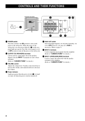
... to turn on ; CONTROLS AND THEIR FUNCTIONS Subwoofer rear panel 1 OUTPUT TO SPEAKERS INPUT 1 FROM AMPLIFIER INPUT 2 HIGH CUT /MONO VOLUME HIGH LOW POWER ON OFF 2 OUTPUT TO SPEAKERS INPUT 1 FROM AMPLIFIER 7 INPUT 2 HIGH CUT 34 /MONO HIGH LOW VOLUME 65 1 POWER switch Press this switch again to set to HIGH if necessary. (Refer to page 9) 6 INPUT 2 terminals Used to input line level signals from the INPUT 1 terminals are sent to these terminals. (Refer to "CONNECTIONS" for details.) 3 VOLUME control Adjusts the volume level.
... to turn on ; CONTROLS AND THEIR FUNCTIONS Subwoofer rear panel 1 OUTPUT TO SPEAKERS INPUT 1 FROM AMPLIFIER INPUT 2 HIGH CUT /MONO VOLUME HIGH LOW POWER ON OFF 2 OUTPUT TO SPEAKERS INPUT 1 FROM AMPLIFIER 7 INPUT 2 HIGH CUT 34 /MONO HIGH LOW VOLUME 65 1 POWER switch Press this switch again to set to HIGH if necessary. (Refer to page 9) 6 INPUT 2 terminals Used to input line level signals from the INPUT 1 terminals are sent to these terminals. (Refer to "CONNECTIONS" for details.) 3 VOLUME control Adjusts the volume level.
Owner's Manual
Page 13
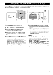
.... 4 Play a source containing bass signal and adjust the amplifier's volume control to the desired listening level. 5 Set the HIGH CUT switch to the LOW or HIGH position. If the desired response cannot be obtained, adjust the HIGH CUT switch and the VOLUME control again. However, if you change , however, depending on the room size, the distance from the subwoofer to the front speakers, and so on. ADJUSTING THE SUBWOOFER BEFORE USE...
.... 4 Play a source containing bass signal and adjust the amplifier's volume control to the desired listening level. 5 Set the HIGH CUT switch to the LOW or HIGH position. If the desired response cannot be obtained, adjust the HIGH CUT switch and the VOLUME control again. However, if you change , however, depending on the room size, the distance from the subwoofer to the front speakers, and so on. ADJUSTING THE SUBWOOFER BEFORE USE...

Owner's Manual
Page 14
... optimum adjustment of each control and the frequency characteristics when this subwoofer is combined with a typical front speaker system. ■EX.1 When combined with a 4" or 6.5" (10 cm or 16 cm) acoustic suspension, 2 way system front speakers HIGH CUT VOLUME HIGH LOW dB 90 80 YST-SW216 70 60 Front speaker 50 40 20 50 100 200 500Hz *This diagram does not depict actual frequency response characteristics...
... optimum adjustment of each control and the frequency characteristics when this subwoofer is combined with a typical front speaker system. ■EX.1 When combined with a 4" or 6.5" (10 cm or 16 cm) acoustic suspension, 2 way system front speakers HIGH CUT VOLUME HIGH LOW dB 90 80 YST-SW216 70 60 Front speaker 50 40 20 50 100 200 500Hz *This diagram does not depict actual frequency response characteristics...
Owner's Manual
Page 15
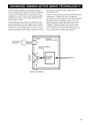
... technique uses a direct connection between the speaker cabinet volume and port, it creates more stable performance and clear bass reproduction without any murkiness. High-amplitude bass sound Cabinet Port Air woofer (Helmholtz resonator) Advanced impedance Converter Active Servo Processing Amplifier Signals Signals of view, the speaker impedance changes depending on the sound frequency. ADVANCED YAMAHA ACTIVE SERVO TECHNOLOGY II In 1988, Yamaha brought to the marketplace speaker systems utilizing YST (Yamaha Active Servo Technology) to Yamaha Active...
... technique uses a direct connection between the speaker cabinet volume and port, it creates more stable performance and clear bass reproduction without any murkiness. High-amplitude bass sound Cabinet Port Air woofer (Helmholtz resonator) Advanced impedance Converter Active Servo Processing Amplifier Signals Signals of view, the speaker impedance changes depending on the sound frequency. ADVANCED YAMAHA ACTIVE SERVO TECHNOLOGY II In 1988, Yamaha brought to the marketplace speaker systems utilizing YST (Yamaha Active Servo Technology) to Yamaha Active...
Owner's Manual
Page 16
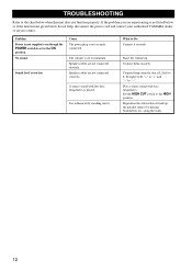
... played. A source sound with bass frequencies. Raise the volume up the parallel surface by standing waves. Connect them securely. along the walls. 12 Cause The power plug is L (left) to L, R (right) to R, "+" to "+" and "-" to minimum. Speaker cables are not connected correctly. Set the HIGH CUT switch to Do Connect it securely. If the problem you are experiencing is too low. Sound level is not listed below or if the instructions...
... played. A source sound with bass frequencies. Raise the volume up the parallel surface by standing waves. Connect them securely. along the walls. 12 Cause The power plug is L (left) to L, R (right) to R, "+" to "+" and "-" to minimum. Speaker cables are not connected correctly. Set the HIGH CUT switch to Do Connect it securely. If the problem you are experiencing is too low. Sound level is not listed below or if the instructions...
Owner's Manual
Page 17
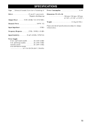
... models AC 110-120/220-240 V, 50/60 Hz 13 Frequency Response 25 Hz - 180 Hz (-10 dB) Input Sensitivity 50 mV (100 Hz, 50 W/5 Ω) Power Supply U.S.A. SPECIFICATIONS Type .....Advanced Yamaha Active Servo Technology II Power Consumption 45 W Driver 25 cm (10") cone woofer Magnetic shielding type Output Power 50 W (100 Hz, 5 Ω 10 %T.H.D) Dynamic Power 100 W, 5 Ω Input Impedance 12 KΩ Dimensions (W x H x D 340 mm x 340 mm x 385 mm (13-3/8" x 13-3/8" x 15-5/32") Weight...
... models AC 110-120/220-240 V, 50/60 Hz 13 Frequency Response 25 Hz - 180 Hz (-10 dB) Input Sensitivity 50 mV (100 Hz, 50 W/5 Ω) Power Supply U.S.A. SPECIFICATIONS Type .....Advanced Yamaha Active Servo Technology II Power Consumption 45 W Driver 25 cm (10") cone woofer Magnetic shielding type Output Power 50 W (100 Hz, 5 Ω 10 %T.H.D) Dynamic Power 100 W, 5 Ω Input Impedance 12 KΩ Dimensions (W x H x D 340 mm x 340 mm x 385 mm (13-3/8" x 13-3/8" x 15-5/32") Weight...

Owner's Manual
Page 20
... AMBROISE CROIZAT BP70 CROISSY-BEAUBOURG 77312 MARNE-LA-VALLEE CEDEX02, FRANCE YAMAHA ELECTRONICS (UK) LTD. Printed in Indonesia WG59120 SIEMENSSTR. 22-34, 25462 RELLINGEN BEI HAMBURG, GERMANY YAMAHA ELECTRONIQUE FRANCE S.A. J A WETTERGRENS GATA 1, BOX 30053, 400 43 VÄSTRA FRÖLUNDA, SWEDEN YAMAHA MUSIC AUSTRALIA PTY, LTD. 17-33 MARKET ST., SOUTH MELBOURNE, 3205 VIC...
... AMBROISE CROIZAT BP70 CROISSY-BEAUBOURG 77312 MARNE-LA-VALLEE CEDEX02, FRANCE YAMAHA ELECTRONICS (UK) LTD. Printed in Indonesia WG59120 SIEMENSSTR. 22-34, 25462 RELLINGEN BEI HAMBURG, GERMANY YAMAHA ELECTRONIQUE FRANCE S.A. J A WETTERGRENS GATA 1, BOX 30053, 400 43 VÄSTRA FRÖLUNDA, SWEDEN YAMAHA MUSIC AUSTRALIA PTY, LTD. 17-33 MARKET ST., SOUTH MELBOURNE, 3205 VIC...


