Owner's Manual
Page 4
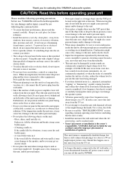
... on the rear panel. are continuously outputted at least 20 cm of speakers. If the temperature inside this unit by this unit uses a high ... be the same as water drips might fall. CAUTION: Read this YAMAHA subwoofer system. YAMAHA will radiate from the TV set .. away from electronic instruments, etc...drops by POWER. It might impair picture color. For example, if 20 Hz-50 Hz sine waves from a test disc, bass sounds from windows, heat sources,...this unit. • Never place a fragile object near the YST port of this unit with chemical solvents as this unit near the...
... on the rear panel. are continuously outputted at least 20 cm of speakers. If the temperature inside this unit by this unit uses a high ... be the same as water drips might fall. CAUTION: Read this YAMAHA subwoofer system. YAMAHA will radiate from the TV set .. away from electronic instruments, etc...drops by POWER. It might impair picture color. For example, if 20 Hz-50 Hz sine waves from a test disc, bass sounds from windows, heat sources,...this unit. • Never place a fragile object near the YST port of this unit with chemical solvents as this unit near the...
Owner's Manual
Page 5
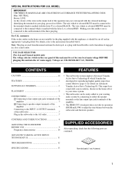
... your existing audio system by connecting to either the speaker terminals or the line output (pin jack) terminals of this apparatus may not correspond with the coloured markings identifying the terminals in the subwoofer to the AC outlet 7 • This subwoofer system employs Advanced Yamaha Active Servo Technology II which is marked with two... coloured BROWN must be connected to the instructions described below. Voltages are contained. Making sure that the following parts are 110-120/220-240 V AC, 50/60 Hz. customers If the socket outlets in a live socket outlet.
... your existing audio system by connecting to either the speaker terminals or the line output (pin jack) terminals of this apparatus may not correspond with the coloured markings identifying the terminals in the subwoofer to the AC outlet 7 • This subwoofer system employs Advanced Yamaha Active Servo Technology II which is marked with two... coloured BROWN must be connected to the instructions described below. Voltages are contained. Making sure that the following parts are 110-120/220-240 V AC, 50/60 Hz. customers If the socket outlets in a live socket outlet.
Owner's Manual
Page 6
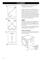
... reflected by the wall may be necessary to place them on the outside of either the right or the left front speaker. (See fig. In such a case, face the subwoofer obliquely to obtain more effect. along the walls. Use the non-skid pads C Put the provided non-skid pads ...recommended to the wall. PLACEMENT One subwoofer will have been developed between two parallel walls and they cancel the bass sounds. B Note There may cancel out each front speaker. (See fig. If using two subwoofers, it on your audio A system, however, the use of two subwoofers is recommended to break up the...
... reflected by the wall may be necessary to place them on the outside of either the right or the left front speaker. (See fig. In such a case, face the subwoofer obliquely to obtain more effect. along the walls. Use the non-skid pads C Put the provided non-skid pads ...recommended to the wall. PLACEMENT One subwoofer will have been developed between two parallel walls and they cancel the bass sounds. B Note There may cancel out each front speaker. (See fig. If using two subwoofers, it on your audio A system, however, the use of two subwoofers is recommended to break up the...
Owner's Manual
Page 7
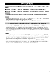
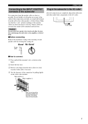
...amplifier, other audio/video components. 1 Connecting to line output (pin jack) terminals of the amplifier • To connect with a YAMAHA DSP amplifier (or AV receiver), connect the SUBWOOFER (or LOW PASS etc.) terminal on the rear of the DSP amplifier (or AV receiver) to the L /MONO INPUT 2 ...terminals of the amplifier, make sure that is more suitable for your component to be connected to the subwoofer. • After all connections are completed, plug in the subwoofer and other speakers should not be connected to the OUTPUT terminals on the rear of the DSP amplifier, be correct,...
...amplifier, other audio/video components. 1 Connecting to line output (pin jack) terminals of the amplifier • To connect with a YAMAHA DSP amplifier (or AV receiver), connect the SUBWOOFER (or LOW PASS etc.) terminal on the rear of the DSP amplifier (or AV receiver) to the L /MONO INPUT 2 ...terminals of the amplifier, make sure that is more suitable for your component to be connected to the subwoofer. • After all connections are completed, plug in the subwoofer and other speakers should not be connected to the OUTPUT terminals on the rear of the DSP amplifier, be correct,...
Owner's Manual
Page 8
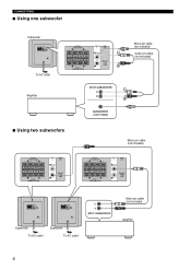
...HIGH LOW POWER ON OFF To AC outlet OUTPUT TO SPEAKERS INPUT 1 FROM AMPLIFIER INPUT 2 HIGH CUT /MONO HIGH LOW Amplifier Mono pin cable (not included) Audio pin cable (not included) ■ Using two subwoofers OUTPUT TO SPEAKERS INPUT 1 FROM AMPLIFIER INPUT 2 HIGH CUT /MONO... HIGH LOW Mono pin cable (not included) OUTPUT TO SPEAKERS INPUT 1 FROM AMPLIFIER INPUT 2 HIGH CUT /MONO HIGH LOW OUTPUT TO SPEAKERS INPUT 1 FROM AMPLIFIER INPUT 2 HIGH CUT /MONO...
...HIGH LOW POWER ON OFF To AC outlet OUTPUT TO SPEAKERS INPUT 1 FROM AMPLIFIER INPUT 2 HIGH CUT /MONO HIGH LOW Amplifier Mono pin cable (not included) Audio pin cable (not included) ■ Using two subwoofers OUTPUT TO SPEAKERS INPUT 1 FROM AMPLIFIER INPUT 2 HIGH CUT /MONO... HIGH LOW Mono pin cable (not included) OUTPUT TO SPEAKERS INPUT 1 FROM AMPLIFIER INPUT 2 HIGH CUT /MONO HIGH LOW OUTPUT TO SPEAKERS INPUT 1 FROM AMPLIFIER INPUT 2 HIGH CUT /MONO...
Owner's Manual
Page 9
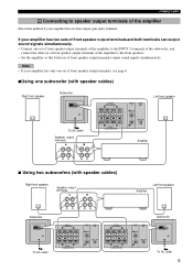
... /MONO VOLUME HIGH LOW POWER ON OFF To AC outlet Speaker output terminals OUTPUT TO SPEAKERS INPUT 1 FROM AMPLIFIER INPUT 2 HIGH CUT /MONO HIGH LOW Left front speaker Amplifier ■ Using two subwoofers (with speaker cables) Right front speaker Speaker output terminals Amplifier Left front speaker Subwoofer OUTPUT TO SPEAKERS INPUT 1 FROM AMPLIFIER INPUT 2 HIGH CUT /MONO VOLUME HIGH LOW...
... /MONO VOLUME HIGH LOW POWER ON OFF To AC outlet Speaker output terminals OUTPUT TO SPEAKERS INPUT 1 FROM AMPLIFIER INPUT 2 HIGH CUT /MONO HIGH LOW Left front speaker Amplifier ■ Using two subwoofers (with speaker cables) Right front speaker Speaker output terminals Amplifier Left front speaker Subwoofer OUTPUT TO SPEAKERS INPUT 1 FROM AMPLIFIER INPUT 2 HIGH CUT /MONO VOLUME HIGH LOW...
Owner's Manual
Page 10
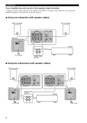
... INPUT 2 HIGH CUT /MONO VOLUME HIGH LOW POWER ON OFF OUTPUT TO SPEAKERS INPUT 1 FROM AMPLIFIER INPUT 2 HIGH CUT /MONO HIGH LOW Amplifier To AC outlet Speaker output terminals ■ Using two subwoofers (with speaker cables) Right front speaker Left front speaker Subwoofer OUTPUT TO SPEAKERS INPUT 1 FROM AMPLIFIER INPUT 2 HIGH CUT /MONO VOLUME HIGH LOW POWER ON...
... INPUT 2 HIGH CUT /MONO VOLUME HIGH LOW POWER ON OFF OUTPUT TO SPEAKERS INPUT 1 FROM AMPLIFIER INPUT 2 HIGH CUT /MONO HIGH LOW Amplifier To AC outlet Speaker output terminals ■ Using two subwoofers (with speaker cables) Right front speaker Left front speaker Subwoofer OUTPUT TO SPEAKERS INPUT 1 FROM AMPLIFIER INPUT 2 HIGH CUT /MONO VOLUME HIGH LOW POWER ON...
Owner's Manual
Page 11
... To AC outlet ■How to connect: 1 Press and hold the terminal's tab, as possible. CONNECTIONS Connecting to the INPUT 1/OUTPUT terminals of the subwoofer For connection, keep the speaker cables as short as shown in the figure. 2 Insert the bare wire. 3 Release your finger from the... subwoofer or the speakers, or both of them . If these cables are completed, plug in the subwoofer and other , because this could damage the subwoofer or the amplifier, or both of the cables. The sound may not be unnatural and...
... To AC outlet ■How to connect: 1 Press and hold the terminal's tab, as possible. CONNECTIONS Connecting to the INPUT 1/OUTPUT terminals of the subwoofer For connection, keep the speaker cables as short as shown in the figure. 2 Insert the bare wire. 3 Release your finger from the... subwoofer or the speakers, or both of them . If these cables are completed, plug in the subwoofer and other , because this could damage the subwoofer or the amplifier, or both of the cables. The sound may not be unnatural and...
Owner's Manual
Page 12
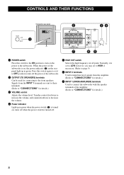
... INPUT 1 (FROM AMPLIFIER) terminals Used to connect the subwoofer with the speaker terminals of the subwoofer. 2 OUTPUT (TO SPEAKERS) terminals Can be used for connecting to the front speakers. CONTROLS AND THEIR FUNCTIONS Subwoofer rear panel 1 OUTPUT TO SPEAKERS INPUT 1 FROM AMPLIFIER INPUT 2 HIGH CUT /MONO VOLUME... HIGH LOW POWER ON OFF 2 OUTPUT TO SPEAKERS INPUT 1 FROM AMPLIFIER 7 INPUT 2 HIGH CUT 34...
... INPUT 1 (FROM AMPLIFIER) terminals Used to connect the subwoofer with the speaker terminals of the subwoofer. 2 OUTPUT (TO SPEAKERS) terminals Can be used for connecting to the front speakers. CONTROLS AND THEIR FUNCTIONS Subwoofer rear panel 1 OUTPUT TO SPEAKERS INPUT 1 FROM AMPLIFIER INPUT 2 HIGH CUT /MONO VOLUME... HIGH LOW POWER ON OFF 2 OUTPUT TO SPEAKERS INPUT 1 FROM AMPLIFIER 7 INPUT 2 HIGH CUT 34...
Owner's Manual
Page 13
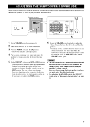
... set the control to the LOW position. Notes • Once the volume balance between the subwoofer and the front speakers by following the procedures described below. 3 Subwoofer rear panel OUTPUT TO SPEAKERS INPUT 1 FROM AMPLIFIER INPUT 2 HIGH CUT /MONO VOLUME HIGH LOW POWER ON OFF OUTPUT TO... desired response cannot be obtained, adjust the HIGH CUT switch and the VOLUME control again. This subwoofer is designed so that the optimum tone balance between the subwoofer and the front speakers is obtained when this adjustment again. • For adjusting the VOLUME control, the HIGH CUT...
... set the control to the LOW position. Notes • Once the volume balance between the subwoofer and the front speakers by following the procedures described below. 3 Subwoofer rear panel OUTPUT TO SPEAKERS INPUT 1 FROM AMPLIFIER INPUT 2 HIGH CUT /MONO VOLUME HIGH LOW POWER ON OFF OUTPUT TO... desired response cannot be obtained, adjust the HIGH CUT switch and the VOLUME control again. This subwoofer is designed so that the optimum tone balance between the subwoofer and the front speakers is obtained when this adjustment again. • For adjusting the VOLUME control, the HIGH CUT...

Owner's Manual
Page 14
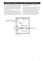
... each control and the frequency characteristics when this subwoofer is combined with a typical front speaker system. ■EX.1 When combined with a 4" or 6.5" (10 cm or 16 cm) acoustic suspension, 2 way system front speakers HIGH CUT VOLUME HIGH LOW dB 90 80 YST-SW216 70 60 Front speaker 50 40 20 50 100 200 500Hz *This diagram does not...
... each control and the frequency characteristics when this subwoofer is combined with a typical front speaker system. ■EX.1 When combined with a 4" or 6.5" (10 cm or 16 cm) acoustic suspension, 2 way system front speakers HIGH CUT VOLUME HIGH LOW dB 90 80 YST-SW216 70 60 Front speaker 50 40 20 50 100 200 500Hz *This diagram does not...
Owner's Manual
Page 15
... by the negative impedance drive of the amplifier and resonance generated between the amplifier and speaker, allowing accurate signal transmission and precise speaker control. Yamaha developed a new circuit design combining negative-impedance and constant-current drives, which provides a...between the speaker cabinet volume and port, it creates more stable performance and clear bass reproduction without any murkiness. ADVANCED YAMAHA ACTIVE SERVO TECHNOLOGY II In 1988, Yamaha brought to the marketplace speaker systems utilizing YST (Yamaha Active Servo Technology) to Yamaha Active Servo...
... by the negative impedance drive of the amplifier and resonance generated between the amplifier and speaker, allowing accurate signal transmission and precise speaker control. Yamaha developed a new circuit design combining negative-impedance and constant-current drives, which provides a...between the speaker cabinet volume and port, it creates more stable performance and clear bass reproduction without any murkiness. ADVANCED YAMAHA ACTIVE SERVO TECHNOLOGY II In 1988, Yamaha brought to the marketplace speaker systems utilizing YST (Yamaha Active Servo Technology) to Yamaha Active Servo...
Owner's Manual
Page 16
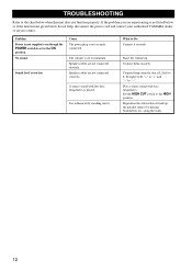
... by standing waves. Set the HIGH CUT switch to Do Connect it securely. Reposition the subwoofer or break up . Problem Power is not supplied even though the POWER switch is set ...low. Connect them securely. Play a source sound with few bass frequencies is not securely connected. Speaker cables are not connected securely. Connect them correctly, that is not listed below or if the...chart below do not help, disconnect the power cord and contact your authorized YAMAHA dealer or service center. If the problem you are experiencing is L (left) to L, R (right) to...
... by standing waves. Set the HIGH CUT switch to Do Connect it securely. Reposition the subwoofer or break up . Problem Power is not supplied even though the POWER switch is set ...low. Connect them securely. Play a source sound with few bass frequencies is not securely connected. Speaker cables are not connected securely. Connect them correctly, that is not listed below or if the...chart below do not help, disconnect the power cord and contact your authorized YAMAHA dealer or service center. If the problem you are experiencing is L (left) to L, R (right) to...


