Owners Manual
Page 4
...dry, clean place - Never pull the wires themselves. • When not planning to prevent fire or damage. Furthermore, do not expose this Yamaha subwoofer system. It might cause a fire, damage to this unit, and/or electric shock. • Super-bass frequencies reproduced by allowing enough spaces ..., dry cloth. • Be sure to generate a howling sound. iii En Yamaha shall not be sure to other surfaces. • Do not cover the rear panel of speakers. If something drops into the YST port located on the floor or other equipment. falls by vibrations, it may cause...
...dry, clean place - Never pull the wires themselves. • When not planning to prevent fire or damage. Furthermore, do not expose this Yamaha subwoofer system. It might cause a fire, damage to this unit, and/or electric shock. • Super-bass frequencies reproduced by allowing enough spaces ..., dry cloth. • Be sure to generate a howling sound. iii En Yamaha shall not be sure to other surfaces. • Do not cover the rear panel of speakers. If something drops into the YST port located on the floor or other equipment. falls by vibrations, it may cause...
Owners Manual
Page 5
... [1] Connecting to line output (pin jack) terminals of the amplifier 6 [2] Connecting to speaker output terminals of the amplifier 8 Connecting to the AC outlet ...11 ADJUSTING THE SUBWOOFER BEFORE USE ...12 AUTOMATIC POWER-SWITCHING FUNCTION 13 Changing the AUTO STANDBY setting ...13 FREQUENCY ...CHARACTERISTICS ...14 ADVANCED YAMAHA ACTIVE SERVO TECHNOLOGY II 15 TROUBLESHOOTING ...16 SPECIFICATIONS ...17 1 En...
... [1] Connecting to line output (pin jack) terminals of the amplifier 6 [2] Connecting to speaker output terminals of the amplifier 8 Connecting to the AC outlet ...11 ADJUSTING THE SUBWOOFER BEFORE USE ...12 AUTOMATIC POWER-SWITCHING FUNCTION 13 Changing the AUTO STANDBY setting ...13 FREQUENCY ...CHARACTERISTICS ...14 ADVANCED YAMAHA ACTIVE SERVO TECHNOLOGY II 15 TROUBLESHOOTING ...16 SPECIFICATIONS ...17 1 En...
Owners Manual
Page 6
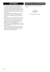
... noise not included in -the-home effect to your stereo system. • This subwoofer can create the best sound quality for various listening conditions by connecting to either the speaker terminals or the line output (pin jack) terminals of the amplifier. • For...8226; This subwoofer system is equipped with a linear port unique to page 15 for reproducing higher quality super-bass sound (refer to Yamaha that the following parts are contained. FEATURES SUPPLIED ACCESSORIES • This subwoofer system employs Advanced Yamaha Active Servo Technology II, which Yamaha has developed...
... noise not included in -the-home effect to your stereo system. • This subwoofer can create the best sound quality for various listening conditions by connecting to either the speaker terminals or the line output (pin jack) terminals of the amplifier. • For...8226; This subwoofer system is equipped with a linear port unique to page 15 for reproducing higher quality super-bass sound (refer to Yamaha that the following parts are contained. FEATURES SUPPLIED ACCESSORIES • This subwoofer system employs Advanced Yamaha Active Servo Technology II, which Yamaha has developed...
Owners Manual
Page 7
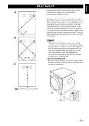
... effect. To prevent this from the subwoofer when listening in A or B. In such a case, face the subwoofer obliquely to break up the parallel surfaces by the wall may die because the sound from C moving by vibrations etc. ( : subwoofer : main speaker) 3 En It also may be necessary... to the wall. English PLACEMENT One subwoofer will have been developed between two parallel walls and they cancel the bass sounds. The placement ...
... effect. To prevent this from the subwoofer when listening in A or B. In such a case, face the subwoofer obliquely to break up the parallel surfaces by the wall may die because the sound from C moving by vibrations etc. ( : subwoofer : main speaker) 3 En It also may be necessary... to the wall. English PLACEMENT One subwoofer will have been developed between two parallel walls and they cancel the bass sounds. The placement ...
Owners Manual
Page 8
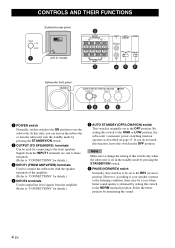
.../LOW/HIGH) switch This switch is to be set to the front speakers. model) 2 OUTPUT TO SPEAKERS R L R L FROM AMPLIFIER INPUT 1 3 INPUT AUTO PHASE 2 STANDBY L /MONO OFF LOWHIGH NORM REV R 45 6 Subwoofer front panel SUBWOOFER SYSTEM YST-RSW300 STANDBY/ON HIGH CUT VOLUME 78 40Hz 140Hz 9 0 10 0 1...condition, there may be used for details.) 3 INPUT1 (FROM AMPLIFIER) terminals Used to connect the subwoofer with the speaker terminals of this switch only when the subwoofer is obtained by pressing the STANDBY/ON switch. 6 PHASE (NORM/REV) switch Normally, this state...
.../LOW/HIGH) switch This switch is to be set to the front speakers. model) 2 OUTPUT TO SPEAKERS R L R L FROM AMPLIFIER INPUT 1 3 INPUT AUTO PHASE 2 STANDBY L /MONO OFF LOWHIGH NORM REV R 45 6 Subwoofer front panel SUBWOOFER SYSTEM YST-RSW300 STANDBY/ON HIGH CUT VOLUME 78 40Hz 140Hz 9 0 10 0 1...condition, there may be used for details.) 3 INPUT1 (FROM AMPLIFIER) terminals Used to connect the subwoofer with the speaker terminals of this switch only when the subwoofer is obtained by pressing the STANDBY/ON switch. 6 PHASE (NORM/REV) switch Normally, this state...
Owners Manual
Page 10
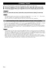
... other audio/video components. [1] Connecting to line output (pin jack) terminals of the amplifier • To connect with a Yamaha DSP amplifier (or AV receiver), connect the SUBWOOFER (or LOW PASS etc.) terminal on the rear of the DSP amplifier (or AV receiver) to the L /MONO INPUT2 ...output (pin jack) terminal(s) ■ Choose [2] (pages 8-9) if your component to be connected to the subwoofer. • After all connections are completed, plug in the subwoofer and other speakers should not be connected to the OUTPUT terminals on the rear of the DSP amplifier, be correct, that the...
... other audio/video components. [1] Connecting to line output (pin jack) terminals of the amplifier • To connect with a Yamaha DSP amplifier (or AV receiver), connect the SUBWOOFER (or LOW PASS etc.) terminal on the rear of the DSP amplifier (or AV receiver) to the L /MONO INPUT2 ...output (pin jack) terminal(s) ■ Choose [2] (pages 8-9) if your component to be connected to the subwoofer. • After all connections are completed, plug in the subwoofer and other speakers should not be connected to the OUTPUT terminals on the rear of the DSP amplifier, be correct, that the...

Owners Manual
Page 11
... cable (not included) Audio pin cable (not included) ■ Using two subwoofers OUTPUT TO SPEAKERS R L INPUT 2 L /MONO R L FROM AMPLIFIER R INPUT 1 Subwoofer OUTPUT TO SPEAKERS INPUT 1 FROM AMPLIFIER INPUT 2 AUTO STANDBY PHASE /MONO OFF HIGH LOW NORM REV POWER ON OFF Subwoofer OUTPUT TO SPEAKERS INPUT 1 FROM AMPLIFIER INPUT 2 AUTO STANDBY PHASE /MONO OFF HIGH LOW NORM...
... cable (not included) Audio pin cable (not included) ■ Using two subwoofers OUTPUT TO SPEAKERS R L INPUT 2 L /MONO R L FROM AMPLIFIER R INPUT 1 Subwoofer OUTPUT TO SPEAKERS INPUT 1 FROM AMPLIFIER INPUT 2 AUTO STANDBY PHASE /MONO OFF HIGH LOW NORM REV POWER ON OFF Subwoofer OUTPUT TO SPEAKERS INPUT 1 FROM AMPLIFIER INPUT 2 AUTO STANDBY PHASE /MONO OFF HIGH LOW NORM...
Owners Manual
Page 12
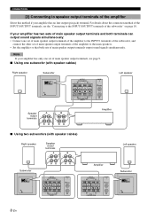
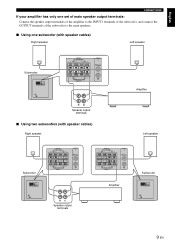
... INPUT 2 AUTO STANDBY PHASE /MONO OFF HIGH LOW NORM REV POWER ON OFF OUTPUT TO SPEAKERS R L INPUT 2 L /MONO R L FROM AMPLIFIER R INPUT 1 Left speaker Speaker output terminals Amplifier ■ Using two subwoofers (with speaker cables) Right speaker Speaker output terminals Left speaker Subwoofer OUTPUT TO SPEAKERS INPUT 1 FROM AMPLIFIER INPUT 2 AUTO STANDBY PHASE /MONO OFF HIGH LOW NORM REV POWER ON...
... INPUT 2 AUTO STANDBY PHASE /MONO OFF HIGH LOW NORM REV POWER ON OFF OUTPUT TO SPEAKERS R L INPUT 2 L /MONO R L FROM AMPLIFIER R INPUT 1 Left speaker Speaker output terminals Amplifier ■ Using two subwoofers (with speaker cables) Right speaker Speaker output terminals Left speaker Subwoofer OUTPUT TO SPEAKERS INPUT 1 FROM AMPLIFIER INPUT 2 AUTO STANDBY PHASE /MONO OFF HIGH LOW NORM REV POWER ON...
Owners Manual
Page 13
... of the subwoofer to the main speakers. ■ Using one subwoofer (with speaker cables) Right speaker Left speaker Subwoofer OUTPUT TO SPEAKERS INPUT 1 FROM AMPLIFIER INPUT 2 AUTO STANDBY PHASE /MONO OFF HIGH LOW NORM REV POWER ON OFF OUTPUT TO SPEAKERS R L INPUT 2 L /MONO R L FROM AMPLIFIER R INPUT 1 Amplifier Speaker output terminals ■ Using two subwoofers (with speaker cables) Right speaker Left speaker Subwoofer OUTPUT TO SPEAKERS INPUT...
... of the subwoofer to the main speakers. ■ Using one subwoofer (with speaker cables) Right speaker Left speaker Subwoofer OUTPUT TO SPEAKERS INPUT 1 FROM AMPLIFIER INPUT 2 AUTO STANDBY PHASE /MONO OFF HIGH LOW NORM REV POWER ON OFF OUTPUT TO SPEAKERS R L INPUT 2 L /MONO R L FROM AMPLIFIER R INPUT 1 Amplifier Speaker output terminals ■ Using two subwoofers (with speaker cables) Right speaker Left speaker Subwoofer OUTPUT TO SPEAKERS INPUT...
Owners Manual
Page 14
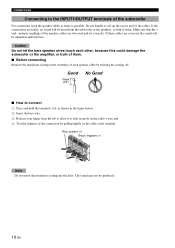
... the tab to allow it to lock securely on the cable at the terminal. Do not bundle or roll up the excess part of the subwoofer For connection, keep the speaker cables as short as shown in the figure below. 2 Insert the bare wire. 3 Release your finger from the... subwoofer or the speakers, or both of each other, because this could damage the subwoofer or the amplifier, or both of them . ■ Before connecting Remove the insulation coating at the extremity of them . Make sure...
... the tab to allow it to lock securely on the cable at the terminal. Do not bundle or roll up the excess part of the subwoofer For connection, keep the speaker cables as short as shown in the figure below. 2 Insert the bare wire. 3 Release your finger from the... subwoofer or the speakers, or both of each other, because this could damage the subwoofer or the amplifier, or both of them . ■ Before connecting Remove the insulation coating at the extremity of them . Make sure...
Owners Manual
Page 15
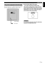
... are completed, plug in the subwoofer and other audio/video components to the proper voltage range (110/120/ 220/230-240 V) of your dealer if you are unsure of the switch is incorrect, set the switch to the AC outlet. VOLTAGE SELECTOR POWER ON OFF (U.S.A. OUTPUT TO SPEAKERS INPUT 1 FROM AMPLIFIER INPUT... has a voltage selector switch on the rear panel. If the preset setting of the correct setting. model) To AC outlet WARNING Do not plug the subwoofer to the AC outlet before setting the VOLTAGE SELECTOR. 11 En
... are completed, plug in the subwoofer and other audio/video components to the proper voltage range (110/120/ 220/230-240 V) of your dealer if you are unsure of the switch is incorrect, set the switch to the AC outlet. VOLTAGE SELECTOR POWER ON OFF (U.S.A. OUTPUT TO SPEAKERS INPUT 1 FROM AMPLIFIER INPUT... has a voltage selector switch on the rear panel. If the preset setting of the correct setting. model) To AC outlet WARNING Do not plug the subwoofer to the AC outlet before setting the VOLTAGE SELECTOR. 11 En
Owners Manual
Page 16
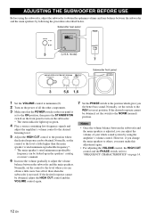
...SUBWOOFER SYSTEM YST-RSW300 STANDBY/ON HIGH CUT VOLUME 40Hz 140Hz 0 10 3 5,6 1,6 Subwoofer front panel 1 Set the VOLUME control to minimum (0). 2 Turn on the power of your whole sound system by following the procedures described below. Normally, set the switch to the level where you can obtain a little more bass effect than the main speaker... the NORM (normal) position. Notes • Once the volume balance between the subwoofer and the main speakers. Subwoofer rear panel PHASE OUTPUT TO SPEAKERS INPUT 1 FROM AMPLIFIER INPUT 2 AUTO STANDBY PHASE /MONO OFF HIGH LOW NORM ...
...SUBWOOFER SYSTEM YST-RSW300 STANDBY/ON HIGH CUT VOLUME 40Hz 140Hz 0 10 3 5,6 1,6 Subwoofer front panel 1 Set the VOLUME control to minimum (0). 2 Turn on the power of your whole sound system by following the procedures described below. Normally, set the switch to the level where you can obtain a little more bass effect than the main speaker... the NORM (normal) position. Notes • Once the volume balance between the subwoofer and the main speakers. Subwoofer rear panel PHASE OUTPUT TO SPEAKERS INPUT 1 FROM AMPLIFIER INPUT 2 AUTO STANDBY PHASE /MONO OFF HIGH LOW NORM ...
Owners Manual
Page 18
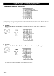
...characteristics when this subwoofer is combined with a typical main speaker system. ■ Example 1 When combined with a 4" or 5" (10 cm or 13 cm) acoustic suspension, 2 way system main speakers: HIGH CUT VOLUME 40Hz 140Hz 0 10 (70Hz) PHASE NORM REV (REV) dB 90 80 YST-RSW300 70 60 Main speaker 50 40 ...an 8" or 10" (20 cm or 25 cm) acoustic suspension, 2 way system main speakers: HIGH CUT VOLUME 40Hz 140Hz 0 10 (50Hz) PHASE NORM REV (REV) dB 90 80 YST-RSW300 70 60 Main speaker 50 40 20 50 100 200 500Hz Frequency response graph* *This diagram does not depict ...
...characteristics when this subwoofer is combined with a typical main speaker system. ■ Example 1 When combined with a 4" or 5" (10 cm or 13 cm) acoustic suspension, 2 way system main speakers: HIGH CUT VOLUME 40Hz 140Hz 0 10 (70Hz) PHASE NORM REV (REV) dB 90 80 YST-RSW300 70 60 Main speaker 50 40 ...an 8" or 10" (20 cm or 25 cm) acoustic suspension, 2 way system main speakers: HIGH CUT VOLUME 40Hz 140Hz 0 10 (50Hz) PHASE NORM REV (REV) dB 90 80 YST-RSW300 70 60 Main speaker 50 40 20 50 100 200 500Hz Frequency response graph* *This diagram does not depict ...
Owners Manual
Page 20
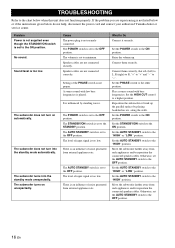
... contact your authorized Yamaha dealer or service center. TROUBLESHOOTING Refer to the "HIGH" position. If the problem you are experiencing is played. The subwoofer does not turn into the standby mode unexpectedly. The POWER switch is set to the OFF position. Speaker cables are not connected...not function properly. Set the POWER switch to the "HIGH" or "LOW" position. Move the subwoofer farther away from such appliances and/or reposition the connected speaker cables. Speaker cables are not connected correctly. The level of the PHASE switch is too low. along the walls...
... contact your authorized Yamaha dealer or service center. TROUBLESHOOTING Refer to the "HIGH" position. If the problem you are experiencing is played. The subwoofer does not turn into the standby mode unexpectedly. The POWER switch is set to the OFF position. Speaker cables are not connected...not function properly. Set the POWER switch to the "HIGH" or "LOW" position. Move the subwoofer farther away from such appliances and/or reposition the connected speaker cables. Speaker cables are not connected correctly. The level of the PHASE switch is too low. along the walls...


